Next Generation Do it Yourself AutoScanner Performs diagnostics on OBD II compliant vehicles Instructions in English, Spanish, and French Instrucciones en Inglés, Español, y Francés Instructions en Anglais, Espagnol, et les Français 15825 Industrial Parkway Cleveland Ohio 44135 USA (EUA) ®
Tool Information Complete the following list. Provide this information when contacting customer support. Serial No: SW ID: Refer to section 4.7 to get the Serial Number (Serial No) and Software Identification (SW ID.) If you have questions or concerns Contact Technical Support: • Phone: 1-800-228-7667 • Web Site: www.actron.com Copyright Information Copyright © 2005-2008 SPX Corporation All rights reserved.
Table of Contents Safety Precautions SF1 Safety Messages . . . . . . . . . . . . . . . . . . . . . . . . . . . . . . . . .SF-1 Signal Words Used: . . . . . . . . . . . . . . . . . . . . . . . . . . . SF-1 Type Styles Used: . . . . . . . . . . . . . . . . . . . . . . . . . . . . SF-2 Icons used: . . . . . . . . . . . . . . . . . . . . . . . . . . . . . . . . . . SF-2 Important Safety Messages . . . . . . . . . . . . . . . . . . . . . . . .SF-2 Getting Started 1 Vehicle Service Information . . . . . . . . .
System Setup / Test 4 System Setup . . . . . . . . . . . . . . . . . . . . . . . . . . . . . . . . . . . . 4-1 Adjusting Display Contrast . . . . . . . . . . . . . . . . . . . . . . Language Setup . . . . . . . . . . . . . . . . . . . . . . . . . . . . . . . Display Test . . . . . . . . . . . . . . . . . . . . . . . . . . . . . . . . . . Keypad Test . . . . . . . . . . . . . . . . . . . . . . . . . . . . . . . . . . Memory Test . . . . . . . . . . . . . . . . . . . . . . . . . . . . . . . . .
Safety Precautions For safety, read, understand and follow all safety messages and instructions in manual and on test equipment before operating tool. Always refer to and follow safety messages and test procedures provided by manufacturer of vehicle and tools. Safety messages below and throughout this manual are reminders to use caution when using tool. Safety Messages Safety messages are provided to help prevent personal injury and equipment damage.
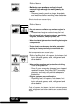
Type Styles Used: Normal type states hazard. Bold type states how to avoid hazard. Italic type states possible results of not avoiding hazard. Icons used: An icon, when present, gives a graphical description of possible hazard. Example: Engine systems can malfunction spilling fuel, oil vapors, hot steam, hot toxic exhaust gases, acid, refrigerant and other debris.
Risk of explosion. • Wear safety goggles and protective clothing. ! WARNING - User and bystander - Even if your everyday glasses have impact resistant lenses, they may NOT be safety glasses, and may not provide adequate protection. • Do not use Tool in environments where explosive vapors may collect. - As in below-ground pits, confined areas, or areas that are less than 18 inches above floor. • Use Tool in locations with mechanical ventilation providing at least 4 air changes per hour.
! WARNING Risk of poisoning. • Use Tool in locations with mechanical ventilation providing at least 4 air changes per hour. Engine exhaust contains odorless lethal gas. • Route exhaust outside while testing with engine running. Poisoning can result in death or serious injury. ! WARNING Battery acid is a highly corrosive sulfuric acid. • Wear safety goggles and protective gloves.
Risk of fire. • Wear safety goggles and protective clothing. - User and bystander - Even if your everyday glasses have impact resistant lenses, they may NOT be safety glasses, and may not provide adequate protection. • Do not position head directly over or in front of throttle body. • Do not pour gasoline down throttle body when cranking or running engine, when working with fuel delivery systems or any open fuel line. - Engine backfire can occur when air cleaner is out of position.
Risk of burns. • Batteries can produce a short-circuit current high enough to weld jewelry to metal. - Remove jewelry such as rings, bracelets and watches before working near batteries. Short circuits can cause injury. ! WARNING Risk of burns. • Do not remove radiator cap unless engine is cold. - Pressurized engine coolant may be hot. • Do not touch hot exhaust systems, manifolds, engines, radiators, sample probe, etc. • Wear insulated gloves when handling hot engine components.
Engine compartment contains electrical connections and hot or moving parts. • Keep personnel, test leads, clothing and other objects clear of electrical connections and hot or moving engine parts. • Do not wear watches, rings, or loose fitting clothing when working in an engine compartment. • Do not place tools on fenders or other places in engine compartment. • To help identify danger zones in test areas use barriers. • Prevent personnel from walking through test area.
! CAUTION Risk of equipment or circuit damage. • Unless specifically directed by manufacturer, make sure ignition is OFF before connecting or disconnecting connectors or any vehicle electrical terminals. • Do not create a short between battery terminals with a jumper wire or tools. Improper equipment use can cause equipment or circuit damage. ! CAUTION Misdiagnosis may lead to incorrect or improper repair and/or adjustment.
Section 1 – Getting Started The Global OBD II AutoScanner® was developed by experts in the automotive service industry to help diagnose vehicles and assist in troubleshooting procedures. AutoScanner® monitors vehicle events and retrieves codes from vehicle’s control module to help pinpoint problem areas. All information, illustrations and specifications contained in this manual are based on the latest information available from industry sources at the time of publication.
Web Site Phone Number Chevrolet Pontiac General Oldsmobile Motors Buick Cadillac Saturn Domestic Ford Vehicles Ford Lincoln Mercury Chrysler Dodge Chrysler Plymouth Eagle Audi Volkswagon BMW MINI Jaguar European Vehicles Volvo Mercedes Land Rover Porsche Saab Acura Honda Lexus Scion Toyota Hyundai Infiniti Nissian Asian Vehicles Kia Mazda Daewoo Subaru Isuzu Geo Mitsubishi Suzuki Chilton Book Company Other Manuals Haynes Publications Bentley Publishers www.chevrolet.com www.pontiac.com www.oldsmobile.
Introduction to On-Board Diagnostics OBD II (On-Board Diagnostics version II) is a system that the Society of Automotive Engineers (SAE) developed to standardize automotive electronic diagnosis. Beginning in 1996, most new vehicles sold in the USA were OBD II compliant. ✓ Technicians now can use the same tool to test any OBD II compliant vehicle without special adapters.
Data Link Connector (DLC) The AutoScanner® uses a Data Link Connector (DLC) to communicate with the vehicle’s control module. ✓ Data Link Connector Location. ❒ Under dashboard on driver side of vehicle. ❒ If Data Link Connector is not located under dashboard, a label should be there telling where the connector can be found.
Diagnostic Trouble Codes (DTCs) ✓ Diagnostic Trouble Codes help determine the cause of a problem or problems with a vehicle. ❒ Diagnostic Trouble Codes (DTCs) consist of a five-digit alphanumeric code. ❒ The Diagnostic Trouble Codes format and general code types are shown below. Bx - Body Cx - Chassis Px - Powertrain Ux - Network Comm.
Within each category (Powertrain, Chassis, Body and Network) of Diagnostic Trouble Codes there are assigned ranges for different vehicle systems.
Section 2 – AutoScanner ® Specifications & Power Information The AutoScanner Keypad Configuration ® 1 LCD Display – 128 x 64 graphic 2 3 4 5 6 7 8 9 display with contrast adjust. UP arrow key – moves UP through functions and picks YES on questions requiring a yes or no answer. ENTER key – selects displayed items. DOWN arrow key – moves DOWN through functions and picks NO on questions requiring a yes or no answer.
Specifications Display: 128 x 64 pixel display with contrast adjust. Operating Temperature: 0 to 50°C (32 to 122°F) Storage Temperature: -20 to 70°C (-4 to 158°F) External Power: 7 to 16 Volts ✓ A minimum of 8.0 V is required for most control modules to operate properly in a vehicle. Power Dissipation: 5 Watts maximum Dimensions: ✓ Thickness 1.125" 28.6 mm Width 3.25" 82.6 mm Length 7.75" 196.9 mm Replacement Part may be available from the manufacturer by contacting customer service.
Display The display has a large viewing area displaying messages, instructions, and diagnostic information. ✓ The Liquid Crystal Display (LCD) is a 128 x 64 pixel display. ❒ Characters used to help operate AutoScanner are: ® Indicates current selection. Indicates additional information is available on previous screen. Indicates additional information is available on next screen. Pending Indicates the code is a pending code. Refer to the Read Codes Section for more details.
Power Internal Battery ✓ ✓ ✓ The Internal Battery allows the operator to Review Data or look up Diagnostic Trouble Code definitions without being connected to a vehicle. Refer to “Tool Does Not Power Up” if there are problems. When the tool is not connected to the vehicle the POWER key turns tool ON and OFF. POWER key for at least 1 second to turn ® ON AutoScanner . ENTER ❒ Press and hold ✓ ✓ ERASE When powered from the internal battery, AutoScanner turns OFF after a period of inactivity.
Vehicle Power When using the OBDII Cable, the ® power to the AutoScanner comes from the vehicle Data Link Connector (DLC.) Diagnostic Connector 1.Find Data Link Connector on Vehicle. •Under dashboard on driver side of vehicle. •If Data Link Connector is not located under the dashboard, a label should be there telling where the connector can be found. 2.Remove Data Link Connector Cover if Required.
3.Connect OBD II Cable to Vehicle. •Make sure pins are not bent. •Carefully align cable plug and push straight into Data Link Connector (DLC). ® 4.Observe AutoScanner Turns On.
® Section 3 – Using AutoScanner : Diagnostic Trouble Codes (DTCs) and Data Read Codes ® The Read Codes function allows the AutoScanner to read the Diagnostic Trouble Codes (DTCs) and Pending Codes from the vehicle’s computer modules. ✓ ✓ ✓ ✓ ✓ ✓ Diagnostic Trouble Codes (DTCs) help determine the cause of a problem or problems with a vehicle. Read Codes can be done with the Key On Engine Off (KOEO) or with the Key On Engine Running (KOER).
1. Select Read Codes. •Use UP or DOWN arrow key to highlight Read Codes. ENTER. •Press 2.View Diagnostic Trouble Codes. •Use UP or DOWN arrow key if more than one Diagnostic Trouble Code is present. •Display shows the number of Diagnostic Trouble Codes present on the top right section of the display. ❒ Example shows a Pending Diagnostic Trouble Code.
Erase Codes The Erase Codes function deletes Diagnostic Trouble Codes and clears I/M Monitors from vehicle’s computer module(s). (See I/M Monitors.) ✓ ✓ The Erase Codes function may also erase View Freeze Data results depending on vehicle. Check vehicle systems completely before using the Erase Code function. ❒ Erase stored Diagnostic Trouble Codes and verify no codes reset. A Diagnostic Trouble Code returns if problem is not fixed or other faults are present.
2.Press ERASE Hot Key. ENTER ERASE OR 2.Select Erase Codes. •Use UP or DOWN arrow key to highlight Erase Codes. ENTER. •Press ✓ If diagnostic results and codes are not to be erased press DOWN arrow key for NO. DIAGNOSTIC MENU ==================== Read Codes Er Erase Codes Erase Codes MIL Status I/M Monitors View Freeze Data Review ERASE ==================== 5 Codes Found. Are you sure you want to Erase Diagnostic Results and Codes ▲ YES ▼ NO 3.
✓ The screen shown appears if engine is running. ERASE ==================== Engine is Running Turn Engine Off Turn Key On Press ENTER To Continue 4.Observe “Command Sent” Message Displays. •Press ENTER. ERASE ==================== Command Sent No Codes Remain Press ENTER To Continue ✓ A Diagnostic Trouble Code may remain if problem is not fixed or other faults are present.
MIL (Malfunction Indicator Lamp) Status MIL Status displays the state of the vehicles computer module(s). ✓ ✓ ✓ MIL Status is most useful if the engine is running. Some manufacturers turn the MIL off if a certain number of drive cycles occur without a fault. The computer’s memory erases Trouble Codes and resets MIL from memory if fault does not occur after 40 warm-up cycles. 1. Select MIL Status. •Use UP or DOWN arrow key to highlight MIL Status. ENTER.
I/M Monitors (Emissions Systems) The I/M Monitors (Inspection / Maintenance) function is used to view a SNAPSHOT of the operations for the Emission System on OBD II vehicles since the Diagnostic Trouble Codes were cleared. ✓ ✓ I/M Monitors is a very useful function. To guarantee no faults make sure all monitors are “ok” or “n/a” and no DTC’s exist. During normal driving conditions, the vehicle’s computer scans the emission system.
✓ I/M Monitors function can be done with the Key On, Engine Running or Off. 1. Select I/M Monitors. •Use UP or DOWN arrow key to highlight I/M Monitors. ENTER. •Press 2.View Summary of Monitor Status. •Use UP or DOWN arrow key.
View Freeze Data View Freeze Data is a “snapshot” of the operating conditions at the time of an emission-related fault. ✓ ✓ Faults with higher priority can overwrite View Freeze Data. Depending on when vehicle DTCs were last erased, Freeze Frame Data may not be stored in vehicles memory. 1. Select View Freeze Data. •Use UP or DOWN arrow key to highlight View Freeze Data. ENTER.
3.View Freeze Data. FREEZE FRAME ==================== DTC that caused freeze frame P0443 Catalyst Temp Bank 1 Sensor 1 S 152 F 4.Select another frame to view (if available.) • Press BACK key. ENTER ERASE 5.Return to DIAGNOSTIC MENU. • Press BACK key.
Review The Review function allows the user to view the previous vehicle tested information. ✓ ® AutoScanner requires power from either the vehicle or the internal battery to use the Review function. 1. Select Review. •Use UP or DOWN arrow key to highlight Review. ENTER. •Press ✓ DIAGNOSTIC MENU ==================== Read Codes Erase Codes MIL Status I/M Monitors View Freeze Data Review Review The Review function has three types of data: ❒ Codes ❒ I/M Monitors ❒ View Freeze Data 2.
Code Lookup Code Lookup is a database of Diagnostic Trouble Code ® (DTC) definitions contained in the AutoScanner . ✓ ✓ Use Code Lookup to look up definitions of Diagnostic Trouble Codes (DTCs.) ® The AutoScanner requires power from vehicle or the internal battery to perform this function. 1. Select Code Lookup. •Use UP or DOWN arrow keys to highlight Code Lookup. ENTER. •Press DIAGNOSTIC MENU ==================== MIL Status I/M Monitors View Freeze Data Review Code Lookup Code Lookup System Setup 2.
✓ ✓ ✓ The DTC Range Definition shows if the definition is manufacturer specific. If the DTC Range Definition does not exist, the Tool shows “No DTC Definition Found. See Service Manual.” See Diagnostic Trouble Code section for DTC Range Definitions. Additional Diagnostic Trouble Codes are available on the DTC Lookup CD software. To View Previous or Next Diagnostic Trouble Code use UP or DOWN arrow key. ENTER ERASE ✓ To enter another Diagnostic Trouble Code, press BACK key.
3-14 Using AutoScanner®: Diagnostic Trouble Codes
Section 4 – System Setup / Test System Setup ✓ System Setup allows: ❒ ❒ ❒ ❒ ❒ ❒ ❒ ✓ Adjustments to display contrast. Selecting language. Checking display pixels. Checking keyboard operations. Checking tools memory. Viewing tools information. Upgrading the tool. System Setup settings remain even if internal battery becomes discharged or is removed. From DIAGNOSTIC MENU: 1.Select System Setup. •Use UP or DOWN arrow key to highlight System Setup. ENTER.
Adjusting Display Contrast From System Setup menu: 1.Select Adjust Contrast. •Use UP or DOWN arrow key to highlight Adjust Contrast. ENTER. •Press 2.Darken or Lighten Display Contrast. •Use UP arrow key to darken Contrast. DOWN arrow •Use key to lighten Contrast. SYSTEM SETUP ==================== Adjust Contrast Adjust Contrast Language Setup Display Test Keypad Test Memory Test Tool Information ADJUST CONTRAST ==================== ▲ Darken ▼ Lighten 80% Press ENTER When Done 3.
Language Setup ✓ English is the Default language. From System Setup menu: 1.Choose Language Setup. •Use UP or DOWN arrow key to highlight Language Setup. ENTER. •Press 2.Select Desired Language. •Use UP or DOWN arrow key to highlight desired language. SYSTEM SETUP ==================== Adjust Contrast LanguageSetup Setup Language Display Test Keypad Test Memory Test Tool Information LANGUAGE SETUP ==================== English English Espanol Francais 3.Save Language Setting. ENTER.
Display Test The Display Test checks the pixels on the display. ✓ The test turns on every pixel of the LCD display 1.Select Display Test. •Use UP or DOWN arrow key to highlight Display Test. SYSTEM SETUP ==================== Adjust Contrast Language Setup DisplayTest Test Display Keypad Test [ Memory Test Tool Information 2. Start Display Test. •Press ENTER. ENTER ERASE 3. Look for Missing Spots. • In solid black characters. • Screen flips through the screens shown below.
Keypad Test The Keypad Test verifies the keys are working correctly. 1.Select Keypad Test. •Use UP or DOWN arrow key to highlight Keypad Test. ENTER. •Press SYSTEM SETUP ==================== Adjust Contrast Language Setup Display Test KeypadTest Test Keypad [ Memory Test Tool Information 2. Press a KEY. • Key name or scroll direction displays. • The only exception is the BACK key. When BACK key is pressed System Setup menu returns. ✓ If System Setup menu does not return, not working.
Memory Test ✓ ✓ ✓ The Memory Test tests RAM, ROM and EEPROM Memory. Dots update along the bottom of the screen to show progress of Memory Test. Run the Memory Test if the tool has trouble: ❒ ❒ ❒ ❒ Reviewing stored data. Displaying trouble code definitions. Doing any function that uses internal memory. Remembering language or contrast settings. 1.Select Memory Test. •Use UP or DOWN arrow key to highlight Memory Test. ENTER.
Tool Information From System Setup menu: 1.Select Tool Information •Use UP or DOWN arrow key to highlight Tool Information. ENTER. •Press 2.View Tool Information. System Setup ==================== Language Setup Display Test Keypad Test Memory Test Tool Information Information Tool Program Mode TOOL INFORMATION ==================== S/N: XXXXXXXXXX SWID: A7B1 Press BACK to Exit 3.Write Down Tool Information. •In space provided on inside front cover. 4.Return to System Setup Menu. •Use BACK key.
Program Mode Use Program Mode for updating and upgrading the tool. Refer to instructions that are provided with update or upgrade.
Section 5 – Troubleshooting Error Messages Check the following if an error message displays: ❒ Make sure vehicle is OBD II compliant. ❒ Verify ignition key is ON and not in the ACCESSORIES ❒ ❒ ❒ ❒ ❒ ❒ ❒ position. Make sure cable connects to vehicle’s Data Link Connector. Look at Data Link Connector and check for cracked or recessed pins, or for any substance that could prevent a good electrical connection. Check for bent or broken pins. Check for blown fuses.
Operating Error or Erroneous Data An Operating Error or Erroneous Data occurs if vehicle’s computer(s) stop(s) communicating with tool. 1.Make Selection. •Use UP arrow key for YES. DOWN arrow •Use key for NO. OPERATING ERROR ==================== Check Connections Try Again ▲ YES ✓ 5-2 ▼ NO See “Error Messages” on page 5-1 for possible causes.
Appendix A – Glossary A/C: Air Conditioner. A/D: Analog to Digital. A/F: Air/Fuel ratio. The proportion of air and fuel delivered to the cylinder for combustion. For example, an A/F ratio of 14:1 denotes 14 times as much air as fuel in the mixture. Ideally the A/F ratio is 14.7:1. ABS: Anti-lock Brake System. AC Clutch Relay: The PCM uses this relay to energize the A/C clutch, turning the A/C compressor on or off.
® AutoScanner : A device that interfaces with a vehicle to Read and Erase Diagnostic Trouble Codes through an OBD II data link. Bank x: The standard way of referring to the bank of cylinders containing cylinder #x. In-line engines have only one bank of cylinders. Most commonly used to identify the location of oxygen sensors. See O2S, Sensor x, Sensor x. BARO: Barometric Pressure Sensor. See MAP Sensor. BBV: Brake Boost Vacuum (Sensor.) BCM: Body Control Module.
Closed Loop (CL): A feedback system that uses the O2 Sensor(s) to monitor the results of combustion. Based on the signal(s) from the O2 sensor(s), the PCM modifies the air/fuel mixture to maintain optimum performance with lowest emissions. In closed loop mode, the PCM can “fine tune” control of a system to achieve an exact result. CMP: Camshaft Position Sensor. CO: Carbon Monoxide; odorless gas produced by incomplete combustion. Continuous Memory Codes: See Pending Codes. CPS: Crankshaft Position Sensor.
Drive Cycle: Vehicle operation for a period of time so the systems can be monitored. DTC: Diagnostic Trouble Code. An alphanumeric identifier for a fault condition identified by the On Board Diagnostic System. Duty Cycle: A term applied to signals that switch between “on” and “off”. Duty cycle is the percentage of time the signal is “on”. For example, if the signal is “on” only one fourth of the time, then the duty cycle is 25%.
EST: Electronic Spark Timing. An ignition system that allows the PCM to control spark advance timing. The PCM determines optimum spark timing from sensor information — engine speed, throttle position, coolant temperature, engine load, vehicle speed, Park/Neutral switch position, and knock sensor condition. EVAP: Evaporative Emissions System. FC: Fan Control. Freeze Frame: Is a “snapshot” of the operating conditions at the time of an emission-related fault. FTP: Federal Test Procedure.
IPC: Instrument Panel Cluster. ISC: Idle Speed Control. A small electric motor mounted on the throttle body and controlled by the PCM. The PCM can control idle speed by commanding the ISC to adjust its position. ISO: International Organization of Standardization also know as International Standards Organization. KAM: Keep Alive Memory. Knock Sensor (KS): Used to detect engine detonation or “knock.” The sensor contains a piezoelectric element and is threaded into the engine block.
MAT: Manifold Air Temperature sensor. A resistance sensor in the intake manifold that sends a voltage signal to the PCM indicating the temperature of the incoming air. The PCM uses this signal for fuel delivery calculations. MIL: Malfunction Indicator Lamp. “Check Engine” or “Service Engine Soon” light are examples of what a MIL is called. A required on-board indicator to alert the driver of an emission-related malfunction. Misfire: Caused by the air fuel ratio being incorrect.
Open Loop (OL): A control system mode that does not monitor the output to verify if the desired achieved results. A fuel delivery system will usually operate in open loop mode during cold engine warm-up because the oxygen sensors are not yet ready to send a signal. Without the oxygen sensor signal, the computer cannot check the actual results of combustion. PCM: Powertrain Control Module.
QDM: Quad Driver Module. RAM: Random Access Memory. Relay: An electromechanical device in which connections in one circuit are switched. Reluctance Sensor: A type of sensor typically used to measure crankshaft or camshaft Speed and/or position, driveshaft speed, and wheel speed. ROM: Read-Only Memory. Permanent programming information stored inside the PCM, containing the information the PCM needs to operate a specific vehicle model/engine combination. RPM: Revolutions Per Minute.
STFT: Short Term Fuel Trim. STS: Service Throttle Soon. TAC: Throttle Actuator Control. TBI: Throttle Body Injection. A fuel injection system having one or more injectors mounted in a centrally located throttle body, as opposed to positioning the injectors close to an intake valve port. Central Fuel Injection (CFI) is another name for TBI on some vehicles. TCC: Torque Converter Clutch. TCM: Transmission Control Module. TCS: Traction Control System for PCM and brakes. TDC: Top Dead Center.
Traction Assist: Assist in traction with brakes only. TTS: Transmission Temperature Sensor. A resistance sensor mounted in the transmission housing in contact with the transmission fluid. It sends a voltage signal to the PCM indicating the temperature of the transmission. VECI: Vehicle Emission Control Information. A decal located in the engine compartment containing information about the emission control systems found on the vehicle.
A-12
Appendix B – Global PID’s Global PID Definitions All global parameter identification data (PID) listed were verified on actual vehicles to guarantee accuracy. It is possible that some newer vehicles may contain data different from that listed. Always refer to vehicle service manual for manufacturer specific PIDs. Remember, always refer to a vehicle service manual for detailed diagnostic procedures when troubleshooting PID values.
Global Data Parameter List: NOTE: Several different causes can have the same parameter indication. For information on diagnostics consult vehicle service manuals. NOTE: Tool will ONLY display the PID’s the vehicle supports.
Fuel Pressure Fuel Rail pressure (gauge) Fuel Rail pressure (mnfld) Fuel System X Ignition Timing Adv Intake Air Temp Load Value Long Term Fuel Trim X Long Term Secondary O2S Fuel Trim Bank X Malfunction Indicator Lamp (MIL) Status MAP Sensor O2Sxx Power Take Off Relative Throttle Position Short Term Fuel Trim (Bx-Sy) Short Term Fuel TrimX Short Term Secondary O2S Fuel Trim Bank X Throttle Position Time run by the engine while MIL is ON Time since DTCs cleared Time Since Engine Start Type of fuel being util
SPX Corporation Limited Warranty THIS WARRANTY IS EXPRESSLY LIMITED TO ORIGINAL RETAIL BUYERS OF SPX ELECTRONIC DIAGNOSTIC TOOLS (“UNITS”). SPX Units are warranted against defects in materials and workmanship for one year (12 months) from date of delivery. This warranty does not cover any Unit that has been abused, altered, used for a purpose other than that for which it was intended, or used in a manner inconsistent with instructions regarding use.
B-5
© 2005-2008 SPX Corporation All Rights Reserved Todos los derechos reservados. Tous droits réservés.