
Instructions Manual


• • • • • • • • • • • • • • • • • • • • • • • • • • • • • • • • • • • • • • • • • • • • • • • • • • • • • • • • • B – 1
B-1
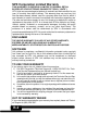
Appendix B – Global PID’s
Global PID Definitions
All global parameter identification data (PID) listed were verified on
actual vehicles to guarantee accuracy. It is possible that some newer
vehicles may contain data different from that listed. Always refer to
vehicle service manual for manufacturer specific PIDs.
Remember, always refer to a vehicle service manual for detailed
dia
gnostic procedures when troubleshooting PID values.
Types of Data Parameters
INPUT: These data parameters are obtained from sensor
circuit outputs. Sensor circuit outputs are inputs
to vehicles PCM. For example, if Oxygen Sensor
circuit was generating a 400mV signal, then
AutoScanner
®
would read O2S (v).40.
OUTPUT: The
se data parameters are outputs or
commands that come directly from computer
module(s). For example, the ignition spark
advance is controlled by PCM, on most vehicles,
monitoring this PID shows spark output from
PCM.
CALCULATED The
se data parameters are calculated after
VALUE: a
nalyzing various inputs to the vehicles computer
module(s). For example, the engine load. The
PCM calculates this from sensor inputs and
displays in a percentage.
PCM VALUE: In
formation that is stored in the computer
module(s) memory and determined to be useful
to service technician. An example of this is
TROUBLE CODE values, the DTC that caused a
freeze frame capture.