Digital Multimeter OPERATING INSTRUCTIONS ® AC V DC V OFF 750 CP7676 4 CYL 200 5 CYL 20 RPM X10 6 CYL 2 8 CYL 20M 4 CYL 2M 5 CYL 200K Instrucciones en español, páginas 37-72 6 CYL OHMS 20K 8 2K 200 COM CYL DWELL CP7676 V 750V AC 200V DC Index Ignition System Testing .............................. 20 - Ignition Coil Testing .............................. 20 - Ignition System Wires .......................... 22 - Hall Effect Sensors/Switches ..............
SAFETY GUIDELINES TO PREVENT ACCIDENTS THAT COULD RESULT IN SERIOUS INJURY AND/OR DAMAGE TO YOUR VEHICLE OR TEST EQUIPMENT, CAREFULLY FOLLOW THESE SAFETY RULES AND TEST PROCEDURES Always wear approved eye protection. Always operate the vehicle in a well ventilated area. Do not inhale exhaust gases they are very poisonous! Always keep yourself, tools and test equipment away from all moving or hot engine parts.
Vehicle Service Manual Sources For Service Information The following is a list of sources to obtain vehicle service information for your specific vehicle. Contact your local Automotive Dealership Parts Department. Contact local retail auto parts stores for aftermarket vehicle service information. Contact your local library. Libraries often allow you to check-out automotive service manuals.
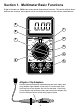
Section 1. Multimeter Basic Functions Digital multimeters or DMMs have many special features and functions. This section defines these features and functions, and explains how to use these functions to make various measurements.
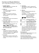
Functions and Display Definitions (Refer to Digital Multimeter illustration on facing page) 1. ROTARY SWITCH Switch is rotated to turn multimeter ON/ OFF and select a function. 8. AC VOLTS This Function is used for measuring AC (Alternating Current) Voltages in the range of 0 to 750V. 2. RPM X 10 This Function is used for measuring engine speed (RPM). 9. DISPLAY Used to display all measurements and multimeter information. 3.
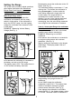
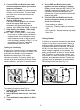
Setting the Range Now assume we set the multimeter to the 2V range. (See Fig. 2) The multimeter display now shows a 1 and nothing else. This means the multimeter is being overranged or in other words the value being measured is larger than the current range. The range should be increased until a value is shown on the display. If you are in the highest range and the multimeter is still showing that it is overranging, then the value being measured is too large for the multimeter to measure.
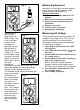
Battery Replacement Fig. 4 Important: A 9 Volt battery must be installed before using the digital multimeter. (See procedure below for installation.) Battery Replacement 1. Turn multimeter rotary switch to OFF position. 2. Remove test leads from multimeter. 3. Remove three screws from back of multimeter. 4. Remove back cover. 5. Install a new 9 Volt battery. 6. Re-assemble multimeter.
Measuring DC Voltage 6. View reading on display - Note range setting for correct units. NOTE: 200mV = 0.2V This multimeter can be used to measure DC voltages in the range from 0 to 200V. You can use this multimeter to do any DC voltage measurement called out in the vehicle service manual. The most common applications are measuring voltage drops, and checking if the correct voltage arrived at a sensor or a particular circuit. Measuring Resistance Resistance is measured in electrical units called ohms (Ω).
4. Touch RED and BLACK test leads together and view reading on display. Display should read typically 0.2Ω to 1.5Ω. If display reading was greater than 1.5Ω, check both ends of test leads for bad connections. If bad connections are found, replace test leads. 5. Connect RED and BLACK test leads across component where you want to check for continuity. 5. Connect RED and BLACK test leads across component where you want to measure resistance. When making resistance measurements, polarity is not important.
Measuring Engine RPM (TACH) 1. Insert BLACK test lead into the COM test lead jack. 2. Insert RED test lead into the V test lead jack. The CP7676 has a RPM X 10 function for measuring engine speed or RPM. When using the RPM X 10 function, you must multiply the display reading by 10 to get actual RPM. If display reads 200, then the actual engine RPM is 10 times 200 or 2000 RPM. 3. Turn multimeter rotary switch to function. 4. Touch RED and BLACK test leads together to test continuity.
Measuring Dwell Dwell measuring was extremely important on breaker point ignition systems of the past. It referred to the length of time, in degrees, that the breaker points remained closed, while the camshaft was rotating. Todays vehicles use electronic ignition and dwell is no longer adjustable. Another application for dwell is in testing the mixture control solenoid on GM feedback carburetors. To Measure Dwell (see Fig. 12): 4 20M CYL 6 200K OHMS Fig.
Section 2. Automotive Testing The digital multimeter is a very useful tool for trouble-shooting automotive electrical systems. This section describes how to use the digital multimeter to test the starting and charging system, ignition system, fuel system, and engine sensors. The digital multimeter can also be used for general testing of fuses, switches, solenoids, and relays. Fuse is blown if display reading indicates an overrange condition.
3. Turn multimeter rotary switch to 200Ω range. Most solenoids and relay coil resistances are less than 200Ω. If meter overranges, turn multimeter rotary switch to next higher range. (see Setting the Range on page 6) 4. Touch RED and BLACK test leads together and view display. Display should read typically 0.2Ω to 1.5Ω. If display reading was greater than 1.5Ω, check both ends of test leads for bad connections. If bad connections are found, replace test leads. 5. Connect BLACK test lead to one side of coil.
Starting/Charging System Testing The starting system turns over the engine. It consists of the battery, starter motor, starter solenoid and/or relay, and associated wiring and connections. The charging system keeps the battery charged when the engine is running. This system consists of the alternator, voltage regulator, battery, and associated wiring and connections. The digital multimeter is a useful tool for checking the operation of these systems. No Load Battery Test 4.
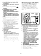
Cranking Voltage - Battery Load Test 4. Connect RED test lead to positive (+) terminal of battery. 5. Connect BLACK test lead to negative (-) terminal of battery. 6. Turn multimeter rotary switch to 20V DC range. 7. Crank engine for 15 seconds continuously while observing display. 8. Test Results. Compare display reading in Step 7 with chart below. This test checks the battery to see if it is delivering enough voltage to the starter motor under cranking conditions. Fig.
Voltage Drops 5. Turn multimeter rotary switch to 200mV DC range. If multimeter overranges, turn multimeter rotary switch to the 2V DC range. (See Setting the Range on page 6) 6. Crank engine until steady reading is on display. Record results at each point as displayed on multimeter. Repeat Step 4 & 5 until all points are checked. 7.
Charging System Voltage Test This test checks the charging system to see if it charges the battery and provides power to the rest of the vehicles electrical systems (lights, fan, radio etc). 7. Turn off all accessories and view reading on display. Charging system is normal if display reads 13.2 to 15.2 volts. If display voltage is not between 13.2 to 15.2 volts, then proceed to Step 13. 8. Open throttle and Hold engine speed (RPM) between 1800 and 2800 RPMs.
Ignition System Testing The ignition system is responsible for providing the spark that ignites the fuel in the cylinder. Ignition system components that the digital multimeter can test are the primary and secondary ignition coil resistance, spark plug wire resistance, hall effect switches/sensors, reluctance pickup coil sensors, and the switching action of the primary ignition coil. Ignition Coil Testing This test measures the resistance of the primary and secondary of an ignition coil.
11. Move RED test lead to secondary ignition coil terminal. Refer to vehicle service manual for location of secondary ignition coil terminal. Verify BLACK test lead is connected to primary ignition coil negative (-) terminal. 12. View reading on display. 13. If vehicle is DIS, repeat Steps 11 and 12 for remaining ignition coils. 14. Test Results - Secondary Coil Typical resistance range of secondary ignition coils is 6.0 - 30.0KΩ. Refer to vehicle service manual for your vehicles resistance range.
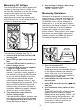
Ignition System Wires This test measures the resistance of spark plug and coil tower wires while they are being flexed. This test can be used for distributorless ignition systems (DIS) provided the system does not mount the ignition coil directly on the spark plug. Test Procedure: 1. Remove ignition system wires one at a time from engine. Always grasp ignition system wires on the boot when removing. Twist the boots about a half turn while pulling gently to remove them.
Hall Effect Sensors/Switches 6. Connect BLACK test lead to 9V battery negative (-) pin. 7. Turn multimeter rotary switch to 200Ω range. Multimeter display should read a small ohm value. 8. Slide a flat blade of iron or magnetic steel between sensor and magnet. (Use a scrap of sheet metal, knife blade, steel ruler, etc.) Multimeter display should indicate an overrange condition. Remove steel blade and multimeter should again display a small ohm value. It is O.K.
Magnetic Pick-Up Coils Reluctance Sensors Reluctance sensors are used whenever the vehicle computer needs to know speed and position of a rotating object. Reluctance sensors are commonly used in ignition systems to determine camshaft and crankshaft position so the vehicle computer knows the optimum time to fire the ignition coil(s) and turn on the fuel injectors. This test checks the reluctance sensor for an open or shorted coil. This test does not check the air gap or voltage output of the sensor. Fig.
Ignition Coil Switching Action Test Procedure (see Fig. 25): 1. Insert BLACK test lead into the COM test lead jack. 2. Insert RED test lead into the test lead jack. 3. Connect RED test lead to TACH signal wire. If vehicle is DIS (Distributorless Ignition System), then connect RED test lead to the TACH signal wire going from the DIS module to the vehicle engine computer.
Fuel System Testing Typical Mixture Control Solenoid Connection The requirements for lower vehicle emissions has increased the need for more precise engine fuel control. Auto manufacturers began using electronically controlled carburetors in 1980 to meet emission requirements. Todays modern vehicles use electronic fuel injection to precisely control fuel and further lower emissions.
Measuring Fuel Injector Resistance Fuel injectors are similar to solenoids. They contain a coil that is switched ON and OFF by the vehicle computer. This test measures the resistance of this coil to make sure it is not an open circuit. Shorted coils can also be detected if the specific manufacturer resistance of the fuel injector is known. Fig. 26 4 750 CYL 200 RPM X10 6 5 CYL 20 Typical Fuel Injector CYL 8 2 CYL 4 20M CYL 5 2M CYL 6 200K OHMS 4.
Testing Engine Sensors In the early 1980s, computer controls were installed in vehicles to meet Federal Government regulations for lower emissions and better fuel economy. To do its job, a computer-controlled engine uses electronic sensors to find out what is happening in the engine. The job of the sensor is to take something the computer needs to know, such as engine temperature, and convert it to an electrical signal which the computer can understand.
Turn multimeter rotary switch to 200Ω range. View reading on display. Compare reading to manufacturer's specification in vehicle service manual. Remove both test leads from sensor. 6. Connect BLACK test lead to sensor GROUND pin. If sensor is 1-wire or 3-wire, then GROUND is sensor housing. If sensor is 2-wire or 4-wire, then GROUND is in sensor wiring harness. Refer to vehicle service manual for Oxygen Sensor wiring diagram. 7. Connect RED test lead to sensor SIGNAL pin. 8.
Temperature Type Sensors A temperature sensor is a thermistor or a resistor whose resistance changes with temperature. The hotter the sensor gets, the lower the resistance becomes. Typical thermistor applications are engine coolant sensors, intake air temperature sensors, transmission fluid temperature sensors, and oil temperature sensors. 8. Turn multimeter rotary switch to desired OHM range.
Position Type Sensors Position sensors are potentiometers or a type of variable resistor. They are used by the computer to determine position and direction of movement of a mechanical device. Typical position sensor applications are throttle position sensors, EGR valve position sensors, and vane air flow sensors. Fig.
Manifold Absolute Pressure (MAP) and Barometric Pressure (BARO) Sensors EGR Valve Position Remove vacuum hose from EGR valve. Connect hand vacuum pump to EGR valve. Gradually apply vacuum to slowly open valve. (Typically, 5 to 10 in. of vacuum fully opens valve.) Depending on hook-up, the display reading will either increase or decrease in resistance. The display reading should either start at or end at the approximate resistance value measured in Step 6. 9. Test Results.
3. Disconnect wiring harness and vacuum line from MAP sensor. 4. Connect jumper wire between Pin A on wiring harness and sensor. 5. Connect another jumper wire between Pin C on wiring harness and sensor. 6. Connect RED test lead to sensor Pin B. 7. Connect BLACK test lead to good vehicle ground. 8. Make sure test leads and jumper wires are not touching each other. 9. Connect a hand held vacuum pump to vacuum port on MAP sensor. 10. Turn Ignition Key ON, but do not start engine! 11.
Mass Air Flow (MAF) Sensors This sensor sends a signal to the computer indicating the amount of air entering the engine. Depending on the sensor design, the signal may be a dc voltage, low frequency, or high frequency type. The CP7676 can only test the dc voltage and low frequency type of MAF sensors. The high frequency type output a frequency that is too high for the CP7676 to measure. The high frequency type MAF is a 3-pin sensor used on 1989 and newer GM vehicles.
Electrical Specifications DC Volts Range: 2V, 20V, 200V Accuracy : ±(1.0% rdg + 2 dgts) 8. Operate Sensor. Start engine and let idle. Display reading should... increase in voltage from Key On Engine OFF for DC type MAF sensors. increase in RPM from Key On Engine OFF for Low Frequency type MAF sensors. Rev Engine. Display reading should... increase in voltage from Idle for DC type MAF sensors. increase in RPM from Idle for Low Frequency type MAF sensors.
Multímetro Digital INSTRUCCIONES DE OPERACION ® AC V DC V OFF 750 CP7676 4 CYL 200 5 CYL 20 RPM X10 6 CYL 2 8 CYL 20M 4 CYL 2M 5 CYL 200K 6 CYL OHMS Indice 20K 8 2K 200 COM CYL DWELL CP7676 V 750V AC 200V DC Precauciones de seguridad ........................................ 38 Información de servicio del vehículo ......................... 39 Inspección visual ........................................................ 39 Especificaciónes eléctricas ...............................
Instrucciones generales de seguridad para trabajar en vehículos Siempre use gafas de seguridad. Siempre opere el motor en áreas bien ventiladas. No inhale los gases de escape... ¡son muy venenosos! Siempre manténgase alejado de toda pieza móvil y caliente así como también a sus herramientas y equipos de pruebas.
Manual de servicio del vehículo - Fuentes para información de servicio A continuación aparece una lista de fuentes para la obtención de información de servicio del vehículo para su vehículo específico. Consulte con su Departamento de Piezas del Concesionario Automotriz local. Consulte con las tiendas minoristas de piezas automotrices locales para información sobre servicio del vehículo de posventa.
Sección 1. Funciones básicas del multímetro Los multímetros digitales o DMMs tienen muchas características y funciones especiales. Esta sección define esas características y funciones y explica cómo usar las mismas para efectuar varias mediciones.
Definiciones de funciones y de pantalla 1. INTERRUPTOR GIRATORIO El interruptor se gira para colocar el multímetro en ON/OFF y seleccionar una función. 9. PANTALLA Usada para mostrar en la pantalla todas las mediciones e información del multímetro. Batería baja (Low Battery) Reemplace la batería interna de 9V si LO BAT aparece en la esquina superior izquierda.
Ajuste del intervalo Supongamos ahora que graduamos el multímetro en el intervalo de 2V (vea Fig. 2). Dos de las preguntas más comunes acerca de los multímetros digitales son:¿Qué significa el Intervalo? y ¿Cómo sé en que Intervalo debo graduar el multímetro? La pantalla del multímetro muestra ahora un 1 y nada más. Esto significa que el multímetro está en un intervalo excesivo o en otras palabras que el valor que se mide es mayor que el intervalo de la corriente.
Este ejemplo muestra que reduciendo el intervalo usted incrementa la exactitud de su medición. Cuando usted cambia el intervalo, cambia la ubicación del punto decimal. Esto cambia la exactitud de la medición incrementando o reduciendo la cantidad de dígitos después del punto decimal. Fig. 4 ® CP7676 DC V 200 AC V OFF 4 750 CYL 5 RPM X10 6 CYL 20 CYL 8 2 CYL CYL 5 2M CYL Importante: debe instalarse una batería de 9 Voltios antes de usar el multímetro digital.
5. Gire el interruptor giratorio del multímetro al intervalo deseado de voltaje. Comience con el intervalo mayor de voltaje y disminuya al intervalo apropiado según requerido, si el voltaje aproximado es desconocido. (Vea Graduación del intervalo en la página 42.) 6. Vea la lectura en la pantalla - Note la graduación del intervalo para las unidades correctas. NOTA: 200mV = 0,2V Medición de voltaje de CC Este multímetro puede usarse para medir los voltajes de CC en un intervalo de 0 a 200V.
3. Inserte la guía de prueba ROJA dentro de la clavija de guía de prueba V . 4. Gire el interruptor giratorio del multímetro al intervalo de 200ý. Junte las guías de prueba ROJA y NEGRA del multímetro y vea la lectura en la pantalla. Típicamente la pantalla debe leer 0,2ý a 1,5ý. Inspeccione ambos extremos de las guías de prueba por malas conexiones, si la lectura en la pantalla fue mayor que 1,5ý. Reemplace las guías de prueba si se hallan malas conexiones. 5.
Pruebas de continuidad Prueba de los diodos La continuidad es una prueba específica de resistencia para determinar si un circuito está abierto o cerrado. El multímetro mostrará la resistencia del circuito. Una resistencia menor que 10ý generalmente indica continuidad. Las inspecciones de continuidad se efectúan generalmente cuando se inspecciona por fusibles quemados, operación del interruptor y cables abiertos o en cortocircuito.
6. Conecte las guías de prueba ROJA y NEGRA a través del diodo y vea la pantalla. La pantalla mostrará una de tres cosas: Una caída típica de voltaje de 0,7V aproximadamente. Una caída de voltaje de 0 voltio. Aparecerá un 1 indicando que el multímetro está en un intervalo excesivo. 7. Cambie las guías de prueba ROJA y NEGRA y repita el paso 6. 8.
Medición del intervalo La medición del intervalo era extremadamente importante en los sistemas interruptores de los platinos de encendido. Se refería a la duración en grados que los platinos permanecían cerrados, mientras el árbol de levas giraba. Los vehículos actuales usan un encendido electrónico y el intervalo no es ajustable. Otra aplicación del intervalo es la prueba del solenoide de control de mezcla en los carburadores de realimentación de GM.
Sección 2. Pruebas automotores con el CP7676 El multímetro digital es una herramienta muy útil para localizar las fallas de los sistemas eléctricos de los automotores. Esta sección describe como usar el multímetro digital para probar el sistema de arranque y carga, el sistema de encendido, el sistema de combustible y los sensores del motor. El multímetro digital puede usarse también para probar fusibles, interruptores, solenoides y relés.
1. Inserte la guía de prueba NEGRA dentro de la clavija de guía de prueba COM. 2. Inserte la guía de prueba ROJA dentro de la clavija de guía de prueba V . 3. Gire el interruptor giratorio del multímetro al rango de 200ý. La mayoría de las resistencias de los solenoides y de las bobinas de los relés son menores que 200ý. Si el medidor indica un rango excesivo gire el interruptor giratorio del multímetro al rango próximo más alto. (Vea Graduación del rango en la página 42). 4.
Prueba del sistema de arranque/carga El sistema de arranque rota el motor. Consiste de la batería, motor del arrancador, solenoide y/o relé del arrancador, y cableado y conexiones asociadas. El sistema de carga mantiene cargada la batería cuando el motor está funcionando. Este sistema consiste del alternador, regulador de voltaje, batería y cableado y conexiones asociadas. El multímetro digital es una herramienta útil para inspeccionar la operación de esos sistemas.
Voltaje de giro (cuando intenta arrancar) - Prueba de carga de la batería 7. Intente arrancar continuamente el motor durante 15 segundos mientras observa la pantalla. 8. Resultados de la prueba. Compare la lectura en la pantalla en el paso 7 con la tabla de abajo. Esta prueba inspecciona la batería para verificar si está entregando suficiente voltaje al arrancador del motor bajo condiciones de intento de arranque. Fig.
Caídas de voltaje 5. Gire el interruptor giratorio del multímetro al rango de 200mV de CC. Si el multímetro sobrepasa la línea, gire el interruptor giratorio del multímetro al rango de 2V de CC. (Vea la Graduación del rango en la página 42) 6. Intente arrancar el motor hasta que se obtenga una lectura estable en la pantalla. Registre los resultados en cada punto mostrado según se muestra en el multímetro. Repita los pasos 4 y 5 hasta que se inspeccionen todos los puntos. 7.
Prueba de voltaje del sistema de carga 8. Abra el regulador y mantenga la velocidad del motor (RPM) entre 1800 y 2800 RPMs. Mantenga esta velocidad a través del paso 11 - Haga que un asistente le ayude a mantener la velocidad. 9. Vea la lectura en la pantalla. La lectura del voltaje no debe variar más que 0,5V. del paso 7. 10. Cargue el sistema eléctrico encendiendo las luces, los limpiadores del parabrisas y graduando el ventilador a la intensidad máxima. 11.
Prueba del sistema de encendido El sistema de encendido es responsable por suministrar la chispa que enciende el combustible en el cilindro. Los componentes del sistema de encendido que el multímetro digital puede probar son la resistencia de la bobina secundaria de encendido, la resistencia del cable de la bujía, interruptores/sensores del efecto Hall, sensores de la bobina de toma de la reluctancia, y la acción conmutadora de la bobina primaria de encendido.
9. Resultados de la prueba - Bobina primaria El rango típico de la resistencia de las bobinas primarias de encendido es de 0,3-2,0ý. Para el rango de resistencias de su vehículo, refiérase al manual de servicio del vehículo. 10. Gire el interruptor giratorio del multímetro al rango de 200Ký (vea Fig. 21). 11. Mueva la guía de prueba ROJA al terminal de la bobina secundaria de encendido. Refiérase al manual de servicio del vehículo para la ubicación del terminal de la bobina secundaria de encendido.
Cables del sistema de encendido Esta prueba mide la resistencia de los cables de la bujía y de la torre de la bobina mientras se flexionan. Esta prueba puede usarse para los sistemas de encendido sin distribuidor (DIS) con la condición que el sistema no monte la bobina de encendido directamente sobre la bujía. Fig. 22750 4 CYL 200 RPM X10 6 5 CYL 20 8 2 CYL 4 20M CYL Rojo 5 2M CYL 6 200K OHMS Negro CYL CYL 8 20K CYL 2K 200 DWELL Procedimiento de prueba: COM 1.
Sensores/Interruptores del efecto Hall Los sensores del efecto Hall se usan siempre que la computadora del vehículo necesite saber la velocidad y posición de un objeto giratorio. Los sensores del efecto Hall se usan comúnmente en los sistemas de encendido para determinar la posición del eje de levas y del cigüeñal de manera que la computadora sepa el momento óptimo para activar la bobina(s) de encendido y los inyectores de combustible.
Bobinas de toma magnética - Sensores de reluctancia Los sensores de reluctancia se usan siempre que la computadora del vehículo necesite saber la velocidad y posición de un objeto giratorio. Los sensores de reluctancia se usan comúnmente en los sistemas de encendido para determinar la posición del eje de levas y del cigüeñal de manera que la computadora sepa el momento óptimo para activar la bobina(s) de encendido y los inyectores de combustible.
Acción conmutadora de la bobina de encendido Esta prueba inspecciona si el terminal negativo de la bobina primaria de encendido conmuta entre ON y OFF por vía del módulo de encendido y de los sensores de posición del árbol de levas/cigüeñal. La acción conmutadora es donde se origina la señal de RPM o tach. (tacómetro). Esta prueba se usa primariamente para una condición de no arranque. DC V 200 Fig.
Prueba del sistema de combustible Conexión típica del solenoide de control de mezcla Los requerimientos para emisiones menores del vehículo han incrementado la necesidad de un control más preciso del combustible del motor. Los fabricantes de automóviles comenzaron a usar carburadores controlados electrónicamente en 1980 para satisfacer los requerimientos de emisiones.
Medición de la resistencia del inyector de combustible 5. Conecte las guías de prueba ROJA y NEGRA a través de las clavijas del inyector de combustible. Asegúrese de conectar las guías de prueba a través del inyector de combustible y no del arnés del cableado. 6. Gire el interruptor giratorio del multímetro al rango deseado de OHMIOS. Comience con el rango más elevado de OHMIOS y disminuya al rango apropiado según sea requerido, si se desconoce la resistencia aproximada.
Prueba de los sensores de motor A comienzos de los años 80 se instalaron controles de computadora en los vehículos para cumplir con las regulaciones del Gobierno Federal para emisiones menores y una mejor economía de combustible. para efectuar esta tarea los motores controlados por computadora usan sensores electrónicos para determinar lo que está sucediendo en el motor.
Conecte la guía de prueba ROJA a cualquiera de las clavijas del calentador. Conecte la guía de prueba NEGRA a la clavija restante del calentador. Gire el interruptor giratorio del multímetro al rango de 200ý. Vea la lectura en la pantalla. Compare la lectura con las especificaciones del fabricante en el manual de servicio del vehículo. Retire ambas guías de prueba del sensor. 6. Conecte la guía de prueba NEGRA a la clavija de CONEXION A TIERRA (GROUND) del sensor.
Sensores de tipo de temperatura Un sensor de temperatura es un termistor o una resistor cuya resistencia cambia con la temperatura. Cuanto más se calienta el sensor más se reduce la resistencia. Las aplicaciones típicas del termistor son los sensores de refrigerante del motor, sensores de temperatura de aire de entrada, sensores de temperatura de fluidos de transmisión y sensores de temperatura del aceite. Fig.
Sensores de tipo de posición Los sensores de posición son potenciómetros o un tipo de resitores variables. Son usados por la computadora para determinar la posición y la dirección del movimiento de un mecanismo mecánico. Las aplicaciones típicas del sensor de posición son los sensores de posición del regulador, sensores de posición de la válvula EGR y sensores de flujo de aire a través de la aleta. Fig.
Vea Sensores de tipo de temperatura en la página 66 para probar el sensor de temperatura del aire de entrada. Posición de la válvula EGR Retire la manguera de vacío de la válvula EGR. Conecte la bomba manual de vacío a la válvula EGR. Aplique vacío gradualmente para abrir lentamente la válvula. (Típicamente de 5 a 10 pulg. de vacío abren completamente la válvula). Dependiendo de la conexión, la lectura de la pantalla aumentará o disminuirá en resistencia.
3. Desconecte el arnés del cableado y la tubería de vacío del sensor MAP. 4. Conecte el cable de puente entre la clavija A en el arnés de cableado y el sensor. 5. Conecte otro cable de puente entre la clavija C en el arnés de cableado y el sensor. 6. Conecte la guía de prueba ROJA a la clavija B del sensor. 7. Conecte la guía de prueba NEGRA a una conexión a tierra en buen estado del vehículo. 8. Asegúrese que las guías de prueba y los cables puente no se toquen entre sí. 9.
Sensores de flujo de aire masivo (MAF) Este sensor envía una señal a la computadora indicando la cantidad de aire entrante en el motor. Dependiendo del diseño del motor, la señal puede ser de tipo de voltaje de cc o de baja o alta frecuencia. El CP7676 puede probar solamente los sensores MAF de tipo de voltaje de cc o de baja frecuencia. La salida del tipo de alta frecuencia es una frecuencia que es demasiado alta para que el CP7676 la mida.
Especificaciónes eléctricas Voltaje de CC Alcance: 2V, 20V, 200V Precisión: ±(1.0% rdg + 2 dgts) {La ecuación es válida solamente para el multímetro en la posición de 4 Cilindros RPM X 10} 8. Opere el sensor Arranque el motor y permita que funcione en vacío. La lectura de la pantalla debe.. - aumentar en voltaje desde la llave en On Motor Off para los sensores MAF de tipo de CC. - aumentar en RPM desde la llave en ON Motor Off para los sensores MAF de tipo de baja frecuencia. Rev.
FULL ONE (1) YEAR WARRANTY SPX Corporation, 15825 Industrial Parkway, Cleveland, Ohio 44135, warrants to the user that this unit will be free from defects in materials and workmanship for a period of one (1) year from the date of original purchase. Any unit that fails within this period will be repaired without charge when returned to the Factory. SPX requests that a copy of the original, dated sales receipt be returned with the unit to determine if the warranty period is still in effect.