
Specifications


1 - 56041403AA, Governor Pressure Sensor
REPAIR PROCEDURE:
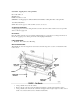
This bulletin involves installing a newly designed governor pressure sensor.
(1) Following the procedures in the applicable service manual, replace the governor pressure sensor with
p/n 56041403AA (See picture below).
(2) Check the throttle valve cable adjustment. Make appropriate adjustments, if necessary, following the
applicable service manual procedure.
How to test your Instrument Cluster (Lamps, Gauges, Indicators)
1. Begin the test with the ignition switch in the Off position.
2. Depress the trip odometer reset button.
3. While holding the trip odometer reset button depressed, turn the ignition switch to the On position, but
do not start the engine.
4. Keep the trip odometer reset button depressed for about ten seconds, until CHEC appears in the
odometer display, then release the odometer reset button.
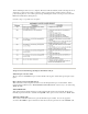
5. A series of three-digit numeric failure messages may appear in the odometer display, depending upon the
failure mode. If a failure message appears, see the Instrument Panel, Gauges and Warning
Indicators/Instrument Panel/Instrument Cluster Failure Message chart for the description and proper
correction. If no failure message appears, the Self-Diagnostics will proceed as described in Step 6.
6. The cluster will begin the odometer walking segment test. This test will require the operator to visually
inspect each odometer segment as it is displayed to determine a pass or fail condition. First, all of the
segments will be illuminated at once; then, each individual segment of the odometer display will be
illuminated in sequence. If any segment in the display fails to illuminate, repeat the test to confirm the
failure. If the failure is confirmed, replace the faulty instrument cluster. Following the odometer walking
segment test, the cluster Self-Diagnostic Test will automatically proceed as described in Step 7.
7. The cluster will perform a bulb check of each indicator lamp that the cluster circuitry controls. If an
individual amber indicator lamp does not illuminate during this test, the instrument cluster should be
removed. However, check that the incandescent lamp bulb is not faulty and that the bulb holder is properly
installed on the circuit board before considering instrument cluster replacement.
8. If the bulb and bulb holder check OK, replace the faulty cluster. Each of the red indicators are
illuminated by a Light Emitting Diode (LED) . If an LED fails to illuminate during this test, the instrument
cluster must be replaced. Following the bulb check test, the cluster Self-Diagnostic Test will automatically
proceed as described in Step 8.
9. The cluster will perform a gauge actuator test. In this test the cluster positions each of the gauge needles
at three different calibration points, then returns the gauge needles to their relaxed positions. If an
individual gauge does not respond properly or at all during the gauge actuator test, the instrument cluster
should be removed. However, check that the gauge terminal pins are properly inserted through the spring-
clip terminal pin receptacles on the circuit board before considering instrument cluster replacement. If the
gauge terminal connections are OK replace the faulty instrument cluster.