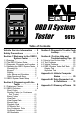
OBD II System Tester '$ # Table of Contents Vehicle Service Information . . 2 Safety Precautions . . . . . . . . . . 3 Section 3: Diagnostic Trouble Code Lookup . . . . . . . . . . . 20 Section 1: Welcome to the OBD II System Tester . . . . . . 4 Section 4: On-Line Help and Troubleshooting Tips 22 1-1 Overview . . . . . . . . . . . . . . . . . . . . . 4 1-2 The OBD II System Tester . . . . . . . . 4 1-3 Diagnostic Connector and Location . 4 1-4 Operating the OBD II System Tester .
Vehicle Service Information The following is a list of publishers who have manuals containing electronic engine control diagnostic information. Some manuals may be available at auto parts stores or your local public library. For others, you need to write for availability and pricing, specifying the make, model and year of your vehicle.
Safety Precautions General Safety Guidelines to Follow When Working on Vehicles To prevent accidents that could result in serious injury and/or damage to your vehicle or test equipment, carefully follow these safety rules and test procedures at all times when working on vehicles: Always wear approved eye protection. Always operate the vehicle in a well-ventilated area.
Section 1: Welcome to the OBD II System Tester 1-1 Overview OBD II (On-Board Diagnostic, second generation) systems are designed to meet or exceed a set of standards and regulations designed to improve air quality. The Environmental Protection Agency (EPA), in conjunction with California Air Research Board (CARB), issued these standards and regulations through the Clean Air Act of 1990. OBD II systems are required to monitor the performance of emission related systems and their components.
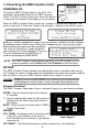
1-4 Operating the OBD II System Tester POWERING-UP Connect the OBD II System Tester to the DLC. This connection will provide power for the OBD II System Tester. The DLC contains power even when the ignition is turned off. Connection to the battery is not necessary. When the OBD II System Tester powers up, a series of screens are displayed. The screens start with a Welcome screen and end with a Help for Instructions screen.
DISPLAY The OBD II System Tester has a 4 line x 20 character liquid crystal display (LCD) for easy viewing. This helps make the OBD II System Tester more user friendly by offering a large viewing area to display most Help and Instructional messages. This puts more information on the display to reduce reference to printed materials. The display will support a number of helpful symbols that will prompt you through test routines.
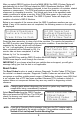
Occasionally, you may be asked a question by Operating Error the OBD II System Tester. These will always be Check Connections! YES or NO questions, and are answered in Try Again? almost the same way you make choices in a NO | Function Menu. In these screens, brackets < > will automatically appear next to the default response. If you wish to accept the default choice, simply press the ENTER key.
Section 2: Diagnosing with the Tester 2-1 Preliminary Checks Before using the OBD II System Tester on your vehicle, it is a good idea to perform a complete visual inspection. You can find the cause of many driveability problems by just looking, thereby saving yourself a lot of time. Check the following items before proceeding with OBD II System Tester testing: o Has the vehicle been serviced recently? Sometimes things get reconnected in the wrong place, or not at all. o Dont take shortcuts.
After you select OBDII Functions from the MAIN MENU the OBD II System Tester will automatically link to the PCM and check the OBD II Readiness Monitors. OBD II Readiness Monitors are strategies designed to test the operation of emission related systems or components. The PCM may perform special tests on a system or component to complete its monitor. The vehicle may have to be operated under certain conditions to initiate a monitor. If the PCM loses power or the codes are erased the monitors will be cleared.
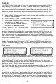
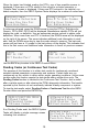
When the tester has finished reading the DTCs, one of two possible screens is displayed. If there are no DTCs stored in the vehicles on-board computer, a System Pass screen is displayed. If there are DTCs stored in the vehicles onboard computer, then the OBD II System Tester displays the number of codes found. System Pass: N o Faults Detected. Press A n y K e y F o r Function Menu Codes Found: 2 U s e [ T o View Codes Write Down Codes [ F o r Reference.
NOTE: If you get an Operating Error message, make sure the DLC adapter cable is securely attached, and the ignition key is ON, then try again. If the problem remains, refer to Section 4: On-Line Help and Trouble-Shooting Tips. If any of these tests indicate a fault, the DTCs will be displayed in the same format as Read Codes. The tester will display codes similar to trouble codes. Press the DOWN arrow to view the pending code(s). Codes Use [ Write For Found: 2 T o View Codes Down Codes [ Reference.
View Data This function is used to view vehicle Parameter Identification Data (PID) in real time. Apart from Read Codes, View Data is the most helpful diagnostic function for determining the cause of a driveability problem. View Data is most often used for observing sensor data and the ON/OFF states of switches, solenoids and relays.
After selecting View Freeze Data, the OBD II System Tester establishes a communication link to the vehicles PCM. All PIDs supported by the vehicle are displayed. Use the UP and DOWN arrow keys to scroll through all selected data parameters. COOLANT ( o F ) 180 ENGINE (RPM) 865] FUEL PRES (PSIG) 3 5 [ FUEL SYSTEM 1 OPEN When done, press the BACK key to return to the OBD II Function Menu.
The OBD II System Tester initializes by **INITIALIZING** establishing the time intervals and then PRETRIG FRAME: - 5 recording the first five Frames of data. When done, the system tester is ready to record data. Press BACK t o Exit To cancel this function, press the BACK key to return to the OBD II Function Menu. If Manual Trigger was selected, then the OBD II System Tester will start recording when the ENTER key is pressed.
If a recording does not exist in the OBD II N o Recording Present System Testers memory, then the message Please Make No Recording Present, Please Make RecordRecording First ing First will display. The Record Data function must be performed in order to play back the data. Press the BACK key to return to the OBD II OBD II Function Menu and select Record Data to make a recording. If recorded data exists, the PIDs, Frame number and Time are displayed. MIL Status ON ABSLT T P S (%) 0.0 CALC LOAD (%) 5.
O2 Monitor Test NOTE: This is NOT an on-demand test. The O2 sensors are not tested when this menu selection is made. The O2 sensors were tested at an earlier time when engine operating conditions were correct. OBD II regulations require the vehicle to monitor and test the oxygen sensors. The O2 Monitor Test selection allows the technician to retrieve the completed test information on the oxygen sensors from the PCM.
Non-Continuous Tests The purpose of this function is to obtain test results for emission-related powertrain components and systems that are not continuously tested. Certain tests are run only once per drive cycle when the vehicle is within proper operating conditions. This function reports the test results after a single drive cycle. The Non-Continuous Test function is useful after a vehicle repair or after clearing the PCMs diagnostic information.
On-Board Systems The purpose of this function is to allow the OBD operation of vehicle component, test or system. Certain manufacturers do not allow OBD II System Testers to control vehicle systems. A screen informing you that the vehicle does not support on boards systems will be displayed in these cases. II System Tester to control the Control o f On-Board Systems Unavailable O n This Vehicle.
A message will state whether the On-Board Readiness Tests are Complete or Not All Supported On-Board Tests are Complete. Press the down arrow key to view the monitor list with their status. Use the vehicle service manuals for detailed information on required emissions-related monitors and their status. N o t All Supported On-Board Readiness Tests A r e Complete. U s e [ T o View Tests The monitor list consists of the OBD II monitor name followed by the monitors Misfire Monitor OK condition.
Section 3: Diagnostic Trouble Code Lookup Code Lookup is a built-in OBD II Generic Diagnostic Trouble Code (DTC) database. The database does not include manufacturer specific DTC definitions, only generic. To look up code definitions, select Code Lookup from either the MAIN MENU or the OBD II Function Menu, then press the ENTER key.
_ Lookup the Codes Definition Press the ENTER key to display the codes definition. When done, press the BACK key to return to the Code Lookup Menu. Lookup Code: P0621 Generator Lamp L Control Circuit Malfunction. _ Scrolling the Code Definitions Once a code definition screen is displayed, you may use the UP/DOWN arrow keys to scroll through the library of code definitions. If the trouble code number does not exist a P0003 No Code Definition Found message will be Undefined Code displayed.
Section 4: On-Line Help and Troubleshooting Tips 4-1 How to Use On-Line Help The tester contains On-Line Help for specific screens, functions, and error messages. When the On-Line Help symbol (|) appears in the lower right-hand corner of the display, OnLine Help is available. Operating Error. Check Connections! T r y Again? No | To enter On-Line Help, press the HELP key. All Help screens are CAPITAL LETTERS.
4. One or more modules drops the communication link: When the OBD II System Tester initially links to the vehicle, it builds a list of all OBD II compliant computer modules. If in the course scanning the vehicle, a module drops the link, a message will display. O n e o r More Modules Lost. Continue Without Them? No | Answering YES will continue operation without the lost module. Answering NO try to restore the communication links to get all modules back to an active status.
The Tool Self-Test menu will display. Two tests can be selected, the Display Test and the Keyboard Test. Use the UP/DOWN arrow keys to move the cursor to option of your choice, then press the ENTER key. Tool Self-Test `1)Display Test 2)Keyboard Test | Display Test After you have selected Display Test as your choice, a screen detailing the test is displayed. The Display Test will fill every pixel of the testers LCD display with a solid black character. Look for pixels that are not black.
Appendix A: Vehicle Computer Basics Basics of Computer-Controlled Vehicles This section explains the engine computer control system, the types of sensors and how the computer controls engine fuel delivery, idle speed and timing. Additional information may be found in technical support books at your local library or auto parts store. The more you know about the computer system, the better you can diagnose vehicle computer problems.
The network of sensors has the job of converting information the computer needs into electrical signals the computer can understand. Signals running from sensors to the PCM are referred to as inputs. Sensors monitor the key parameters shown in the table. NOTE: Not all engines use every sensor listed.
Open and Closed Loop Modes: Open or closed loop operation refers to the way the computer is deciding how much fuel to add to the air entering the engine. During cold start and other low temperature situations, the computer operates in open loop mode. This means that it is relying on a set of internal calculations and data tables to decide how much fuel to add to the incoming air.
About Diagnostic Trouble Codes (DTCs) Where do they come from and what are they for? Engine computers can find problems The computer systems in todays vehicles do more than control engine operations they can help you find problems, too! Special testing abilities are permanently programmed into the computer by engineers. These tests check the components connected to the computer which are used for (typically): fuel delivery, idle speed control, spark timing, emission systems, and transmission shifting.
KAL makes it easy to fix computer-controlled vehicles Using the KAL OBD II System Tester to obtain trouble codes is fast and easy. Trouble codes give you valuable knowledge - whether you go for professional service or do it yourself.
Poorly running engine, No Malfunction Indicator Lamp Most likely, this condition is not due to computer system failures, but reading codes can still be useful as part of a basic troubleshooting procedure. Check wiring and bulb for Check Engine light failures. Refer to vehicle service manual for additional diagnostic information. On OBD II vehicles, the Malfunction Indicator Lamp also signals an emissionscontrol related failure.
Appendix B: Data Parameter List & Definitions All data parameters or parameter identification data (PID) listed in Appendix B were verified on actual vehicles to guarantee their accuracy. Definitions used to describe all PIDs were obtained from reliable sources and are accurate at the time of printing. It is possible that some newer vehicles may contain data different from that listed in Appendix B. Always refer to a vehicle service manual for vehicle-specific PIDs.
COOLANT (°F) (Engine Coolant Temperature - PCM input) COOLANT (°C) Display: Numeric temperature value: -40 to 419 (°F) or -40 to 215 (°C). This is a measure of the engines coolant temperature. A voltage signal is sent to the PCM from a sensor that is in contact with the coolant. The voltage signal increases as temperature increases. The PCM converts this voltage reading to a degree measurement.
IAT TEMP (°C) (Intake Air Temperature - PCM input) IAT TEMP (°F) Display: Numeric temperature value: -40 to 419 (°F) or -40 to 215 (°C) This is a measure of intake air temperature to determine correct air/fuel ratios and spark timing operations. The voltage from a thermistor in the intake manifold is sent to the PCM. The PCM converts this voltage signal to a numerical temperature value. IGN ADV (DEG) (Ignition Advance - PCM output) Display:-64 to +63.
MAP (HG) (Manifold Absolute Pressure - PCM input) MAP (KPA) Display: numeric inches of Mercury (HG) or kiloPascals (KPA) The Manifold Absolute Pressure sensor converts intake manifold vacuum or pressure to an electric signal and sends it to the PCM. The PCM converts this signal into a numerical pressure value expressed in kiloPascals (kPa) or inches of Mercury (Hg). The MAP reading will vary with engine speed and load.
SECONDARY AIR (Secondary Air System Status - PCM output) Display: UPSTR, DNSTR, ATMSP The secondary air injection system on newer vehicles is controlled by the PCM. The PCM use actuators to control this pollution control system. Secondary air can be added the exhaust system near the exhaust manifold (before any catalytic converts), at the catalytic convert(s) or not at all.
Appendix C: Glossary of Terms A/C: Air Conditioning. A/F: Air/Fuel ratio. This refers to the proportion of air and fuel delivered to the cylinder for combustion. For example, if you have 14 times more air than fuel (by weight) then the A/F ratio is 14:1 (read as fourteen to one). The ideal operating A/F ratio in an automotive application is 14.7:1. AC Clutch Relay: The PCM uses this relay to energize the A/C clutch, turning the A/C system on or off.
CKP REF: Crankshaft Reference. coolant. It sends a voltage signal to the PCM indicating the temperature of the coolant. The PCM uses this signal for control of fuel delivery, spark advance, and EGR flow. CKP: Crankshaft Position Sensor. Closed Loop (C/L): This is when a control system performs an action (expecting a certain result), then checks the results and corrects its actions (if necessary) until the desired results are achieved. Example: Fuel delivery.
DiagnosticTrouble Codes: Diagnostic Trouble Codes (DTC) indicate a malfunction flagged by a vehicle computer. The computer will display a corresponding code based on a lookup table in the program of the on-board computer. Most systems have the ability to store codes in memory, which are commonly referred to as history codes or soft codes. Malfunctioning circuits will generate continuous Check Engine lamp illumination, called current codes or hard codes.
EGR: Exhaust Gas Recirculation. The EGR system recirculates exhaust gases back into the intake manifold to reduce NOx emissions. The EGR valve controls the flow of exhaust gases back into the intake manifold. Some EGR valves are operated with a vacuum signal while others are electrically controlled. The amount of EGR valve opening determines the flow through the valve. EGR Recirculation is only used during warm engine cruise conditions. EGR flow at other times can cause stalling or no starts.
Hall Effect Sensor: This sensor is a three wire-type of sensor containing electronic circuitry. Two wires supply power and ground, while a third wire carries the sensor signal back to the PCM. The sensor consists of a permanent magnet and a small module containing a transistorized Hall Effect switch. A small air gap separates the sensor and the magnet. The magnetic field causes the Hall switch to turn on and send out a low voltage signal.
MAF: Mass Air Flow Sensor. This sensor measures the amount of air entering the engine using a wire or film heated to a specific temperature. Incoming air cools the wire. The MAF sensor sends a frequency or voltage signal (depending on sensor type) to the PCM based on the voltage required to maintain that temperature. The signal frequency or voltage increases when the mass of the incoming air goes up. This gives the PCM information required for control of fuel delivery and spark advance.
delivered (The PCM assumes everything in the fuel system is performing properly). In open loop operation, the PCM does not check the actual amount of fuel delivered. Thus, a faulty fuel injector or incorrect fuel pressure can change the amount of fuel delivered and the PCM would not know it. In general, a control system operates in open loop mode only when there is no practical way to monitor the results of an action; i.e. Fuel delivery during cold engine warmup.
TBI: Throttle Body Injection. A fuel injection system having one or more injectors mounted in a centrally located throttle body, as opposed to positioning the injectors close to SFI or SEFI: an intake valve port. TBI is also called CenSequential Fuel Injection or Sequential Elec- tral Fuel Injection (CFI) in some vehicles. tronic Fuel Injection. A fuel injection system that uses one or more injectors for each cyl- TDC: inder. The injectors are mounted in the in- Top Dead Center.
VIN: Vehicle Identification Number. This is the factory-assigned vehicle serial number. This number is stamped on a number of locations throughout the vehicle, but the most prominent location is on top of the dashboard on the drivers side, visible from outside the vehicle. The VIN includes information about the vehicle, including where it was built, body and engine codes, and a sequential build number. VSS: Vehicle Speed Sensor. This sensor sends a frequency signal to the PCM.
NOTES 45
NOTES 46
NOTES 47
THREE (3) YEAR LIMITED WARRANTY Actron Manufacturing Company (Actron) warrants to the original purchaser that this product will be free from defects in materials and workmanship for a period of three (3) years from the date of original purchase. Any unit that fails within this period will be replaced or repaired at Actrons discretion without charge. If you need to return product, please follow the instructions below.