
Data Sheet

Rev C.
Model Selection
The L16 has 3 configuration choices: Stroke, Gear Ratio and
Controller. L16 options are identified according to the
following model numbering scheme:
L16-SS-GG-VV-C
Feature Options
SS: Stroke 50, 100, 140 (mm)
GG: Gear reduction
ratio (refer to load
curves above)
35, 63, 150
(lower ratios are faster but push
less force, and vice versa)
VV: Voltage 12 vdc or 6 vdc (-R only)
C: Controller P Potentiometer Feedback
S Limit Switches
R RC Linear Servo
L16 Controller Options
Option S – End of Stroke Limit Switches
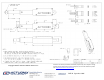
WIRING: (see last page for pin numbering)
1 - Red – Motor V+
2 – Black – Motor V- (Ground)
-S actuators are ideal for manually controlled applications and
simple two position automated mechanisms. The –S actuators
have limit switches that will turn off power to the motor when
the actuator reaches within 0.5mm of the end of stroke.
Internal diodes allow the actuator to reverse away from the
limit switch. The limit switches cannot be moved once the
actuator is manufactured. While voltage is applied to the
motor power pins, (1 & 2) the actuator extends. Reverse the
polarity and the actuator retracts. This can be accomplished
manually with a DPDT switch or relay, or using an H-Bridge
circuit. The –S model cannot be used with the LAC control
board.
Option P – Potentiometer Position Feedback
WIRING: (see last page for pin numbering)
1 - Orange – Feedback Potentiometer negative reference rail
2 - Purple – Feedback Potentiometer wiper
3 - Red – Motor V+ (6V or 12V)
4 - Black – Motor V- (Ground)
5 - Yellow – Feedback Potentiometer positive reference rail
-P actuators are suited to automatically controlled positioning
systems, but they can also be driven manually. The –P
actuators have no built in controller, but do provide an analog
position feedback signal that can be input to an external
controller. While voltage is applied to the motor power pins,
(3 & 4) the actuator extends. Reverse the polarity and the
actuator retracts. This can be accomplished manually with a
DPDT switch or relay, or using an H-Bridge circuit. Position of
the actuator stroke can be monitored via the internal linear
potentiometer. Provide any stable low and high reference
voltage on pins 1 & 5, then read the position signal on pin 2.
The voltage on pin 2 will vary linearly between the two
reference voltages in proportion to the position of the
actuator stroke.
The L16 –P actuator can be used as a linear servo by
connecting the actuator to an external controller such as the
LAC board offered by Firgelli. This control board reads the
position signal from the L16, compares it with your input
control signal then commands the actuator to move via an on-
board H-bridge circuit. The LAC allows any one of the
following control inputs: Analog 0-3.3V or 4-20mA, or Digital
0-5V PWM, 1-2ms Standard RC, or USB. The RC input
effectively transforms your L16 into a linear servo, which is a
direct replacement for any common hobby servo used in RC
toys and robotics. Refer to the LAC datasheet for more
details.
0
5
10
15
20
25
30
35
0 50 100 150 200 250
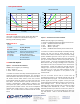
Speed (mm/s)
Force (N)
Load Curves
35:1
63:1
150:1
0
100
200
300
400
500
600
0 50 100 150 200 250
Current (mA)
Force (N)
Current Curves
L16 Specifications
Copyright 2016
Actuonix Motion Devices Inc.