
Data Sheet
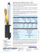

Model Selection
The P16 has 3 configuration choices: Stroke, Gear Ratio and
Controller. P16 options are identified according to the
following model numbering scheme:
P16-SS-GG-VV-C
Feature Options
SS: Stroke 50, 100, 150,200 (mm)
GG: Gear reduction
ratio (refer to load
curves above)
22, 64, 256 :1
(lower ratios are faster but push
less force, and vice versa)
VV: Voltage 12 Volts DC
C: Controller P Potentiometer Feedback
S Limit Switches
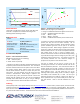
P16 Controller Options
Option S – End of Stroke Limit Switches
WIRING: (see last page for pin numbering)
1 - Red – Motor V+ (12V)
2 – Black – Motor V- (Ground)
–S actuators are ideal for manually controlled applications and
simple two position automated mechanisms. The –S actuators
have limit switches that will turn off power to the motor when
the actuator reaches within 0.5mm of the end of stroke.
Internal diodes allow the actuator to reverse away from the
limit switch. The limit switches cannot be moved once the
actuator is manufactured. While voltage is applied to the
motor power pins, (1 & 2) the actuator extends. Reverse the
polarity and the actuator retracts. This can be accomplished
manually with a DPDT switch or relay, or using an H-Bridge.
The –S model cannot be used with the LAC control board.
Option P – Potentiometer Position Feedback
WIRING: (see last page for pin numbering)
1 - Orange – Feedback Potentiometer negative reference rail
2 - Purple – Feedback Potentiometer wiper
3 - Red – Motor V+ (12V)
4 - Black – Motor V- (Ground)
5 - Yellow – Feedback Potentiometer positive reference rail
-P actuators are suited to automatically controlled positioning
systems, but they can also be driven manually. The –P
actuators have no built in controller, but do provide an analog
position feedback signal that can be input to an external
closed loop controller. While voltage is applied to the motor
power pins, (3 & 4) the actuator extends. Reverse the polarity
and the actuator retracts. This can be accomplished manually
with a DPDT switch or relay, or using an H-Bridge circuit.
Position of the actuator stroke can be monitored by providing
any stable low and high reference voltage on pins 1 & 5, then
reading the position signal on pin 2. The voltage on pin 2 will
vary linearly between the two reference voltages in
proportion to the position of the actuator stroke.
The P16 –P actuator can be used as a linear servo by
connecting the actuator to an external controller such as the
LAC board offered by Actuonix. This control board reads the
position signal from the P16, compares it with your input
control signal then commands the actuator to move via an on-
board H-bridge circuit. The LAC allows any one of the
following control inputs: Analog 0-3.3V or 4-20mA, or Digital
0-5V PWM, 1-2ms Standard RC, or USB. The RC input
effectively transforms your P16 into a linear servo, which is a
direct replacement for any common hobby servo used in RC
toys and robotics. Refer to the LAC datasheet for more
details.
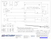
Ordering
Small quantity orders can be placed directly online at www.Actuonix.com. Purchase orders, volume quotes, and custom order
requests can be sent to sales@Actuonix.com. MOQ for custom strokes, cables or connectors is typically 500pcs. Each actuator
ships with two mounting brackets and #8-32 mounting hardware. The cable length is approximately 300mm and connector is a
0.1” pitch female socket connector. The thread in the end of the round aluminum shaft is M8x1.25.
Copyright 2016 Actuonix Motion Devices Inc.