
Data Sheet
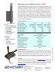

Model Selection
The PQ12 has 3 configuration choices: Gear Ratio, Voltage and
Controller. PQ12 options are identified according to the
following scheme:
PQ12-GG-VV-C
feature options
GG: Gear reduction
ratio (refer to load
curves above)
30, 63, 100
(lower ratios are faster but push
less force, and vice versa)
VV: Voltage 6, 12
(DC volts)
C: Controller P Potentiometer Feedback
S Limit Switches
R RC Linear Servo (6V Only)
PQ12 Controller Options
Option S – End of Stroke Limit Switches
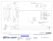
WIRING: (see next page for pin numbering)
1- Limit Switch Detection (Optional)
2- Actuator Motor Power
3- Actuator Motor Power
4- Not Connected
5- Not Connected
The –S actuators have limit switches that will turn off power to
the motor when the actuator reaches within 1mm of the end
of stroke. Internal diodes allow the actuator to reverse away
from the limit switch. The limit switches cannot be moved.
While voltage is applied to the motor power pins (2 & 3) the
actuator extends. Reverse the polarity and the actuator
retracts. This can be accomplished manually with a DPDT
switch or relay, or using an H-Bridge circuit. The –S model
cannot be used with the LAC control board. Pin #1 can be
used to sense when the actuator has reached the end limits.
See our FAQ page for a simple schematic to light an LED when
the limits are reached.
All the information provided on this datasheet is for information purposes only and is subject to change.
Purchase and use of all Actuonix Actuators is subject to acceptance of our Terms and Conditions of sale
as posted here:
http://www.Actuonix.com/terms.asp
Option P – Potentiometer Position Feedback
WIRING: (see next page for pin numbering)
1 – Feedback Potentiometer negative reference rail
2 – Actuator Motor Power
3 – Actuator Motor Power
4 – Feedback Potentiometer positive reference rail
5 – Feedback Potentiometer wiper
The –P actuators have no built in controller, but do provide
analog position feedback. While voltage is applied to the
motor power pins (2 & 3) the actuator extends. Reverse the
polarity and the actuator retracts. Position of the actuator
stroke can be monitored using the internal linear
potentiometer. Provide any stable low and high reference
voltage on pins 1 & 4, then read the position signal on pin 5.
The voltage on pin 5 will vary linearly between the two
reference voltages in proportion to the position of the
actuator stroke. Connect to an LAC board for easy interface
with any of the following control signals: Analog 0-5V or 4-
20mA, or Digital 0-5V PWM, 1-2ms Standard RC, or USB.
Option R – RC Linear Servo
WIRING: (see last page for pin numbering)
1 - RC input signal (RC-servo compatible)
2 - Power (+6 VDC)
3 - Ground
Note: Reversing polarity on pins 2 and 3 may cause damage
-R actuators are ideally suited to use in robotics and radio
control models. The –R actuators or ‘linear servos’ are a direct
replacement for regular radio controlled hobby servos. The
desired actuator position is input to the actuator on lead 1 as
a positive 5 Volt pulse width signal. A 2.0 ms pulse commands
the controller to fully retract the actuator, and a 1.0 ms pulse
signals it to fully extend. If the motion of the actuator, or of
other servos in your system, seems erratic, place a 1–4Ω
resistor in series with the actuator’s red V+ lead wire. The
PQ12–R Linear Servos are designed to work with typical RC
receivers and battery packs. Consequently, they also are
compatible with Arduino control boards, VEX Microcontrollers
and many other similar boards designed for robotics.
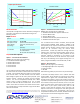
Load Curves
0
5
10
15
20
25
30
0 10 20 30 40 50
Force (N)
Speed (mm/s)
30:1
63:1
100:1
Current Curves
0
100
200
300
400
0 10 20 30 40 50
Force (N)
Current (mA)
30:1 6v
63:1 6v
100:1 6v
30:1 12v
63:1 12v
100:1 12v
PQ12 Specifications