User’s Manual Conversational and g-code CNC 3500i
Controls of the 3500i Controls of the 3500i Keys on visual display unit Power control keys Data Entry keys Key Function Plus - Minus toggle key Key Function NC Start key (i.e. run a program) CLEAR key clears selections, i.e. values, Stop key (i.e.
Key Controls of the 3500i Axis Jog keys Navigation keys Function Key Function JOG Cycles the CNC through manual movement modes: RAPID JOG, JOG FEED, JOG @ 100, JOG @ 10, JOG @ 1 Manually moves X+ axis in positive direction ARROW over, up, down to move highlight Manually moves X- axis in negative direction Manually moves Y+ axis in positive direction Manually moves Y- axis in negative direction Potentiometer for feed rate and spindle speed override Feed rate Spindle speed Manually moves Z+ axis in
Controls of the 3500i Keyboard Installation The machine builder determines whether the system supports a keyboard option. If this option is supported, plug a USB keyboard into the 3500i. There is no keyboard equivalent for the E-STOP, so emergency shutdowns cannot be performed through the keyboard. Keyboard Equivalent Key Strokes Key Function CLEAR Alt + c ARROWS Arrows ENTER Enter X X Y Y Z Z U U START Alt + s HOLD Alt + h Peripherals Supported: USB memory devices; e.g.
Manual Information Manual Information Message symbols This symbol indicates that there is one or more of the following risks when using the described function Danger to work piece Danger to fixtures Danger to tool Danger to machine Danger to operators Damage! This symbol indicates that there is risk of damage, or electrical shock if instructions are not adhered to.
Manual Information Model, Software and Features This manual describes functions and features provided by 3500i as of the following NC software numbers. CNC model NC software number ACU-RITE 3500i CNC Software 689 871-01 The machine tool builder adapts the usable features of the CNC to his machine by setting machine parameters. Some of the functions described in this manual may therefore not be among the features provided by the CNC on your machine tool.
Manual Information New Functions of Software 689 871-01-02 CAM now includes a Save button to allow quickly saving progress. Ctrl-S can now be used as well. CAM geometry creation dialogs now support copying and pasting between dialogs. ARC Help Forms now support all planes. As such, X, Y, and Z parameters are all available and indicated as optional. User needs to decide which of these are actually required for the particular instance.
Manual Information Changed Functions of Software 689 871-01-01 Feed & Speed Calculator in MDI was changed; see page 55. Feeds & Speeds Table functionality and description was expanded; see page 68. Additional information for the Repeat blocks feature is being provided; see page 147. 689 871-01-02 Linear and Arc Engraving cycles now apply active program rotation. Mirroring and scaling are still cancelled at the start of the cycle.
Contents Introduction Machining Fundamentals Manual Data Input Tool Management Program Management Conversational Editing Programming: Canned Cycles, subprograms Drawing Programs Running a Program on the Machine CAM: Programming G-code Edit, Help, & Advanced Features Software Update ACU-RITE 3500i 1 2 3 4 5 6 7 8 9 10 11 12 ix
x
Table of Contents Controls of the 3500i Keys on visual display unit .......................................................................................iv Numerical keys ........................................................................................................iv Data Entry keys........................................................................................................iv Axis Keys ....................................................................................................
1.2 Visual Display Unit Operating Panel with Touch Screen display ............................................................ 6 Screen Navigation.................................................................................................... 6 Menus, Dialogues, and Forms................................................................................. 7 General Operating Guidelines.................................................................................. 8 Main Operating Modes ..................
Absolute and incremental work piece positions .................................................... 31 Absolute work piece positions.......................................................................... 31 Incremental work piece positions ..................................................................... 31 Setting the datum .................................................................................................. 32 Fixture Offsets .............................................................
Tool Management 4.1 Tool Table Tool Table / Tool Management .............................................................................. 60 Tool Compensation Required Data ........................................................................ 60 Tool numbers / Tool names ................................................................................... 61 Locating the Tool Table.......................................................................................... 61 Editing the tool table..........
Tool Compensation Path........................................................................................ 81 Path of Tool During Tool Compensation ........................................................... 81 Intersecting Points ............................................................................................ 82 Compensation Around Acute Angles................................................................ 82 General Precautions..............................................................
Conversational Editing 6.1 Conversational Programming Getting Started .................................................................................................... 102 Program Edit Screen............................................................................................ 103 Program Edit buttons ...................................................................................... 104 Conversational Data Input Cycles ........................................................................
Rapid .................................................................................................................... 122 Rapid Move..................................................................................................... 122 Rapid Move - EndPoint: .................................................................................. 122 Rapid Move - Angle and Radius: ..................................................................... 123 Rapid Move - Angle and X:.............................
7.2 Canned Cycles Canned Cycles ..................................................................................................... 149 Drilling Cycles ...................................................................................................... 150 Drilling, Tapping, and Boring ........................................................................... 150 Basic Drill Cycle ..............................................................................................
7.3 Probing Cycles Tool, and Spindle Probe cycles ............................................................................ 199 Tool Probe Cycles ................................................................................................ 200 Tool Probe Calibration Cycle ........................................................................... 201 Tool Length and Diameter Offset Preset........................................................ 203 Manual Tool-Length Offset Preset......................
Drawing Programs 8.1 Draw Viewing Programs ............................................................................................... 256 Starting Draw....................................................................................................... 257 View Options Menu............................................................................................. 258 Adjust View Menu ...............................................................................................
CNC Program .................................................................................................. 279 CAM Mode Mouse Operations ........................................................................... 280 CAM Mode Screen .............................................................................................. 281 Activating CAM Mode ......................................................................................... 281 Creating a New Program .......................................
Pocket Cycle ........................................................................................................ 303 Basic tab: ........................................................................................................ 303 Setup tab: ....................................................................................................... 303 Pocket Finish Cycles............................................................................................ 305 Bottom tab: ......................
Tool Table ............................................................................................................ 325 Setting up the Tool Table ................................................................................ 327 Importing a Tool Table .................................................................................... 327 Exporting a Tool Table..................................................................................... 327 Tool Paths ..........................................
Canceling edits to a program block:................................................................ 360 Restore edits to a program block:................................................................... 360 Program Text Editing ........................................................................................... 361 Inserting Text:................................................................................................. 361 Overwriting Text: ...................................................
Order of Execution............................................................................................... 386 Programming Non-modal Exact Stop: ................................................................. 387 In-Position Mode (Exact Stop Check): ................................................................ 387 Contouring Mode (Cutting Mode) : ..................................................................... 387 Setting Stroke Limit: .......................................................
Software Update 12.1 Updating System Software Software Update.................................................................................................. 438 Procedure for updating the software................................................................... 438 Off-Line Software 13.1 3500i Off-Line Software Off-Line Simulator................................................................................................ 440 System Requirements ......................................................
Introduction
1.1 The 3500i 1.1 The 3500i The ACU-RITE 3500i control is a touch screen workshop-oriented contouring control that enables you to program conventional machining operations right at the machine in an easy-to-use conversational programming language. The control is also capable of running, and editing g-code (ISO format) programs. It is designed for milling and drilling machine tools, as well as machining centers, with up to four axes.
1.1 The 3500i Powering Up the CNC Machine When you power-on the CNC, ensure that the E-STOP switch is in the in position. Turn on the CNC machine according to the builder's instructions. Turn the power switch on to the 3500i console. The 3500i completely resets, activating the startup screen. With the EMERGENCY STOP button out, reset the servo drive by pressing the SERVO RESET key. Press the Home button. Press the Start button. The 3500i default display is the Manual screen.
1.1 The 3500i E-Stop, Servo Reset, and CNC Shutdown Press E-STOP to disengage the servos and then revert to Manual Data Input Mode. Touch Shut Down to display the Shut Down dialogue. Touch Shut Down to power down the CNC, or touch Cancel to cancel the shut down. The shutdown takes less than a minute. The 3500i will let you know when it is safe to turn power off. Or, you can touch Reboot (or press the ENTER key) to re-start the 3500i. Follow the builder's instructions for turning off the machine.
1.1 The 3500i Writing Programs The 3500i allows many features to be used without having to write a program. But for operations that repeat or complex machining it is best to write a program. Before you start to write a program, determine the work-holding device and the location of Part Zero (the point to which all movement is referenced).
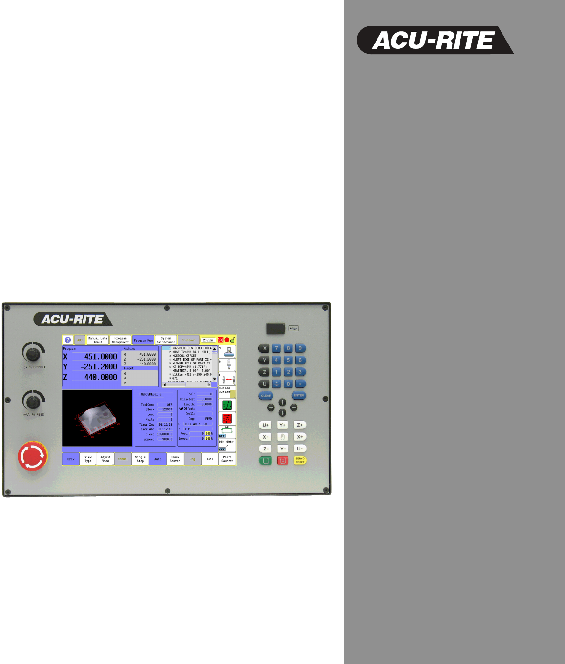
1.2 Visual Display Unit 1.2 Visual Display Unit Operating Panel with Touch Screen display The ACU-RITE 3500i has a 12.1-inch Flat-Panel Color Touch Screen Display. The following list of items are also located on the front panel. See "Manual Data Input" on page 20 for mapping information of the start up screen. For information regarding the Key pad, see "Console Key Pad" on page 19.
1.2 Visual Display Unit Menus, Dialogues, and Forms This section describes general overview of the pop-up menus, dialogues, and forms provided by the 3500i. Complete information is provided in this manual where specific examples of actions are being explained. Pop-up menus allow you to make a selection from multiple options. When a pop-up appears touch the desired selection or use the ARROW keys and touch Enter. Some features will require entering data in a form.
1.2 Visual Display Unit General Operating Guidelines The following provides the general operating guidelines for the 3500i. Mode specific function buttons are always located on the left vertical edge of the screen. Scroll bars automatically appear when the window information does not completely fit into the current window size. The active operating mode is highlighted in blue in the top menu bar. The activated key in the side bar will highlight in blue also.
1.2 Visual Display Unit Program Management provides access to existing programs for running, simulating or editing. New programs can be created here with access to the CAM, and Draw features. Programs can also be copied to or from a USB memory device (like a memory stick or thumb drive), or network. See "Accessing Program Management" on page 88 for a complete description. Program Run allows a selected program to either auto run without pausing, or single step through a program as it is running.
1.2 Visual Display Unit Upper Menu and Status Information Bar The 3500i display screen upper bar always remains the same regardless of the operation or function that is being preformed, and general status information. See "Manual Data Input" on page 20 for a complete description of the screen layout.
1.2 Visual Display Unit Machine function buttons Machine function buttons are always located on the right side of the screen. They remain constant, and do not change regardless of the current action the machine is performing. They provide an easy way to perform supported machine functions. The actual features available depend on the machine builder.
1.2 Visual Display Unit Keyboard An on screen QWERTY keyboard will automatically pop-up when you enter a field that requires text information input. The 3500i touch screen keyboard becomes visible (pop-up) when text, and numerical information is required for an action that is currently being taken. When the information has been entered using the keyboard, and the Use button has been touched, the keyboard will disappear from the screen.
1.2 Visual Display Unit Additional Buttons The following additional buttons are always available on the keyboard. 1 2 3 4 5 6 7 8 Enter Button, same as ENTER key. Special Characters Button - shows other characters. Copy Button - copy information in the current field to the copy buffer. Paste Button - paste previously copied information in the current field. Clear Button - clear the current field. Shift Button - switch between upper and lower case.
1.2 Visual Display Unit Programming Sliders The following list describes the slider controls shown here. 1 2 3 4 5 6 7 8 9 Jump to the beginning Page Up Up Arrow Scroll Bar Arrow Down Page Down Jump to the end Horizontal Bar Window Slider Scroll Bar(s) are used to scroll through the active window. Window Slider(s) are used to resize a window on the screen. Scroll bars, and/or sliders are available in all screens that require navigation assistance.
1.2 Visual Display Unit Numeric touch pad An on screen numeric touch keypad will automatically pop-up when you enter a field that requires numeric data input. When information has been entered using the on screen numeric keypad, touch the Enter button. The next field requiring data input will be highlighted. When finished, touch the Use button to enter the data, or touch the Cancel button to cancel out of the current dialogue. Touching either button will remove the numeric touch pad from the screen.
1.2 Visual Display Unit Calculator The on screen numeric keypad has a built in calculator feature. The 3500i on screen numeric touch pad calculator feature is available whenever the on screen numeric keypad is open. To open the calculator feature, touch the Calculator button. 1 2 3 Calculator button Advanced Calculator button Calculator result window The calculator works like a normal handheld calculator. When using the calculator touching = puts the result in the result window.
1.2 Visual Display Unit Context Sensitive Help The Acu-Rite 3500i uses an intuitive method to aid the user when assistance is desired. When assistance is needed with a feature, the User Manual can be displayed directly at the point which describes the pertinent feature. To use Help, as the example screen shows; the console is in Manual Data Input, and a Linear Engraving cycle is being programed. It is desired to see descriptions of the cycle parameters, and the cycle itself.
1.2 Visual Display Unit The following buttons are available when using Help. Button Function Help button activates the User Manual Help screen window. Back moves back through the current viewing history. Next moves forward through the current viewing history. Show/Hide Tree toggles the view of the left tree-view section. Maximize/Minimize toggles between window and full screen views. Exit closes the User Manual help window, and returns to current operating screen.
1.2 Visual Display Unit Console Key Pad The following keys are located on the console key pad. There is also a quick reference guide located at the beginning of this manual, see "Controls of the 3500i" on page ii. 1 2 Axis keys, use to select the required axis. Numeric keys, use to enter numeric data, included is the toggle key for “Plus/Minus” data entry. 3 CLEAR key, use to clear selections such as values entered. 4 ENTER key, use to activate selections, and entries.
1.3 Main Operating Mode Screens 1.3 Main Operating Mode Screens Display navigation The three main operating modes: Manual Data Input, Program Management, and Program Run each have there own screen. A condensed description of these has been provided here on how to navigate, become familiar with the information that is being provided. Manual Data Input The Manual Data Input screen (default screen), displays several windows, and program buttons. The following list maps what is being viewed on this screen.
1.3 Main Operating Mode Screens Program Management Screen The Program Management screen displays several windows, and buttons. The following list maps what is being viewed on this screen. See “Accessing Program Management” on page 88. 1 2 3 4 5 6 7 8 Program Management main mode button. Program List window. Program Text Preview area. Program Display area. Horizontal Button Bar. Program Type Information Display, and available computing space. Program Sort Button.
1.3 Main Operating Mode Screens Program Run Select a program to run. Touch the Program Run button. The CNC loads the program. The name of the currently loaded program is displayed in the Program Name field at the center of the screen. There are two modes of programed operation: Single-Step Mode: Runs a program one block at a time. See “Using Draw with running programs” on page 270. Automatic Mode: Runs a program automatically, without pausing. See “Auto mode” on page 266.
1.4 Accessories: 1.4 Accessories: Available accessories include a selection of electronic Touch Probes, and Hand Wheels. Touch probes Touch Probe Function software option.
1.4 Accessories: TT 140 tool touch probe for tool measurement The TT 140 is a triggering 3-D touch probe for tool measurement and inspection. Your CNC provides three cycles for this touch probe with which you can measure the tool length and radius automatically either with the spindle rotating or stopped. The TT 140 features a particularly rugged design and a high degree of protection, which make it insensitive to coolants.
Machining Fundamentals
2.1 Fundamentals of Positioning 2.1 Fundamentals of Positioning Position encoders and reference marks The machine axes are equipped with position encoders that register the positions of the machine table or tool. Linear axes are usually equipped with linear encoders, rotary tables and tilting axes with angle encoders. When a machine axis moves, the corresponding position encoder generates an electrical signal. The CNC evaluates this signal and calculates the precise actual position of the machine axis.
2.1 Fundamentals of Positioning Reference system A reference system is required to define positions in a plane or in space. The position data are always referenced to a predetermined point and are described through coordinates. The Cartesian coordinate system (a rectangular coordinate system) is based on the three coordinate axes X, Y and Z. The axes are mutually perpendicular and intersect at one point called the datum. A coordinate identifies the distance from the datum in one of these directions.
2.1 Fundamentals of Positioning Designation of the axes on milling machines The X, Y and Z axes on your milling machine are also referred to as tool axis, principal axis (1st axis) and minor axis (2nd axis). The assignment of the tool axis is decisive for the assignment of the principal and minor axes.
2.1 Fundamentals of Positioning Setting the pole and the angle reference axis The pole is set by entering two Cartesian coordinates in one of the three planes. These coordinates also set the reference axis for the polar angle PA. Coordinates of the pole (plane) Reference axis of the angle X/Y +X Y/Z +Y Z/X +Z Absolute and incremental polar coordinates Absolute polar coordinates always refer to the pole and the reference axis.
2.1 Fundamentals of Positioning Angle Measurements Polar measurement of angles is referenced from the 3 o'clock position (0 degrees). Positive angles rotate in a counterclockwise direction; negative angles rotate in a clockwise direction.
2.1 Fundamentals of Positioning Absolute and incremental work piece positions Absolute work piece positions Absolute coordinates are position coordinates that are referenced to the datum of the coordinate system (origin). Each position on the work piece is uniquely defined by its absolute coordinates.
2.1 Fundamentals of Positioning Setting the datum Fixture Offsets A production drawing identifies a certain form element of the work piece, usually a corner, as the absolute zero datum. When setting the datum, you first align the work piece along the machine axes, and then move the tool in each axis to a defined position relative to the work piece. Set the display of the CNC either to zero or to a known position value for each position.
2.1 Fundamentals of Positioning Example2: SetZero See "Absolute Zero Set" on page 140 for more information on using the SetZero cycle. The work piece drawing shows holes (1 to 4) whose dimensions are shown with respect to an absolute datum with the coordinates X=0 Y=0. Holes 5 to 7 are dimensioned with respect to a relative datum with the absolute coordinates X=450, Y=750.
2.2 Manual Machine Positioning 2.2 Manual Machine Positioning Jog Mode Moves You can make or change jog moves when the CNC is in Manual Data Input Mode, Teach Mode, or in the Tool Page; and the servos are on. Jog Mode Description Rapid Default rapid speed for continuous jogs. Actual speed determined at machine setup. Feed Continuous jog at feedrate determined at machine setup. Jog: 100 Conventional Jog Mode, increment set to 100 times machine resolution.
2.2 Manual Machine Positioning Adjusting the Feedrate The Feedrate Override rotary switch can be used to override the currently active feedrate or rapid rate for machine moves. The switch provides a range of 0% to 150%. Setting the switch to 100% will allow the actual feedrate or rapid rate currently active to be used. The machine builder determines the default rapid rate and maximum feedrate at setup. If the CNC is shut down, the configuration file reloads these default rates at the next power-on.
36 2 Machining Fundamentals 2.
Manual Data Input
3.1 Manual Data Input (MDI) 3.1 Manual Data Input (MDI) Overview Manual Data Input allows data input for simple machining operations. Manual operation, single step operation, and single commands can be entered. The following describes the concepts, and formats used with the ACU-RITE 3500i CNC. These topics are being introduced in this chapter.
3.1 Manual Data Input (MDI) Manual Data Input Mode Settings Features (or settings) that remain active for more than one operation are referred to as modal. Modal features remain active until you change or cancel them. Most CNC functions are modal. As an example, if the CNC is in Rapid Mode, it executes all moves at the rapid rate until you initiate Feed Mode. The CNC can be in several modes, as long as the modes do not conflict. Before making a manual move, make any necessary mode settings.
3.1 Manual Data Input (MDI) Manual Data Input Menu Bar The following table describes the bottom bar menu buttons. Button Function Mill Line opens the Mill Line pop-up dialogue where information can be entered to mill a line. Mill Arc opens the Mill Arc pop-up dialogue where information can be entered to mill an arc (or radius). Drill Cycles opens a sub menu for selection of type of drilling cycle, e.g. Basic, Pecking, Counter Bore etc.). Selection of a cycle opens a form for data input.
3.1 Manual Data Input (MDI) Draw & Manual bottom menu bar buttons. Button Function Touching the Draw button will view real time drawing of the work piece as it is being machined. Manual button when touched will cancel the program. MDI Menu Page two The following table describes the bottom bar page two menu buttons. Button Function Record is used to toggle between recording all Manual Data Input commands entered in standard MDI. If record is on, all commands successfully run will be recorded.
3.1 Manual Data Input (MDI) Manual Data Input Operations The following explains a few of the machining operations that are available with Manual Data Input. Examples have been provided to explain an overview to the operator of the 3500i’s capabilities. The Drill Cycles, Pocket Cycles, and Other Cycles buttons access sub menus of different types of cycles that are available in each of these categories. A cycle, or operation is ran by pressing Use.
3.1 Manual Data Input (MDI) Mill Arc manual data input View Touch the View button to view the Mill Arc data input graphically. Touch the Exit button to return to the Mill Arc dialogue. The view option is available with all manual data actions. Touch the Use button to run the operation. Touch the Start button to execute the machining cycle, or touch the Manual button to cancel.
3.1 Manual Data Input (MDI) Manual Data Input Cycles The MDI Cycles are grouped in three categories as described in the following groups.
3.1 Manual Data Input (MDI) When a Cycles button is touched, the available cycles in that category are listed. Touch the name of the cycle that is to be executed by the machine to display the manual data input form. A full description of the above listed Cycles, and programming applications are provided in this manual. Refer to chapter 7 "Canned Cycles" on page 149. Pocket Cycle Example From the bottom menu bar touch the Pocket Cycles button. Touch Rectangular in the sub menu.
3.1 Manual Data Input (MDI) The More button is used to enter additional (or optional) parameters regarding the machining of the pocket such as corner radius, side finish stock, etc. These additional parameters are not typically required. To exit from the More Menu, touch the More button again. The required parameters are displayed. Rectangular Pocket Cycle data input View Touch the View button to view the rectangular pocket data input graphically, and is useful for verification.
3.1 Manual Data Input (MDI) Block History The MDI block history allows the operator to record all cycles that are programmed into the MDI to be retrieved or saved into a part program. By default the recording of the MDI cycles is on and can be turned off by toggling the Record button on the second set of menu bar MDI buttons. This block history can be cleared by touching the Clear History button on the second set of menu bar buttons or saved into a part program by touching the Save History button.
3.1 Manual Data Input (MDI) G-code MDI The ACU-RITE 3500i also has G-code Manual Data Input mode, and allows you to command moves without creating a part program. MDI also is a quick way to program one move, or a series of moves that are used only one time. Refer to chapter 11 "G-Code Program Editing" on page 352. To enter G-code MDI mode, use the G-code MDI button on the bottom menu bar. Type an instruction on the command line of the Program Area, and touch START.
3.1 Manual Data Input (MDI) MDI Touch Screen Feature Dialogues The 3500i allows the operator to do quick machine functions directly from the Manual Data Input screen. Touching on any of these marked touch screen zones opens a dialogue for data input. The data entered only affects the manual operation of the control, it does not affect the automatic Program Run mode. Depending on where the screen is touched within each “Zone”, the dialogue will open defaulting to the item that was touched within the zone.
3.1 Manual Data Input (MDI) Program Preset Touching the numerical values in the Preset Axes zone opens the Program Preset dialogue, allowing the operator to preset one or more axes. Touch the Preset Axes zone, or select an axis in the zone by touching that axes numerical value. The Program Preset dialogue opens, and the axis that was touched is automatically selected. The cursor will appear in the data entry field next to the selected axes.
3.1 Manual Data Input (MDI) Move to Target Location Touching in the Target location zone opens the Move to Target Location dialogue, allowing the operator to move one or more axes to a specific location. The operator can enter position locations for the active axes, feed rate (value or Rapid) and absolute or incremental positioning. If the feed rate is not specified, the 3500i will use the last programmed feed rate.
3.1 Manual Data Input (MDI) Tool The tool dialogue allows the operator to temporarily adjust tool settings or mount a new tool. If only a tool number is entered, the system will mount the tool, and use the values stored in the tool table. If any of the other values are entered (e.g. diameter, length, etc) the tool settings for the tool number provided will be modified. The new values will not be stored in the tool table as they are temporary manual settings. Touch the Tool Location zone.
3.1 Manual Data Input (MDI) Offset Offset allows the operator to activate a new offset from the Offset table, or modify existing values in the Offset table. If only a fixture offset number is entered, the system will activate the offset provided from the offset table. If any of the other values are entered (e.g. X, Y, Z, etc.) the offset settings for the fixture offset number will be modified and the new values are stored in the offset table. Touch the Offset Location zone to open the Offset dialogue.
3.1 Manual Data Input (MDI) Basic Modals Basic Modals allow the operator to set some of the basic modals for the system. In this dialog, the operator is allowed to adjust the current modal settings of the system (plane, absolute/incremental, inch/mm and rapid/feed mode). Touch the Basic Modals Location zone. The Basic Modals dialogue opens. Adjust the current modal settings of the system by touching on fields that require adjustment.
3.1 Manual Data Input (MDI) Feed and Speed This allows the operator to adjust the current feed and speed. There are two modes for this, each having it’s own dialogue. When the current active tool has values entered for the feed and speeds in the tool table the “Feed and Speed Calculator” dialogue will open. This dialogue allows the operator to use the feed and speed values as is from the Feed and Speed tool table.
3.1 Manual Data Input (MDI) When the current tool has no values entered into the Feed and Speed table the Feed and Speed dialogue will be opened. Touch the Feed and Speed Location zone. The Feed and Speed dialogue opens. To adjust the values directly, enter a new value in the Feed, and/or Speed fields. Touch Use to activate the changes, or press Cancel to exit without making any changes.
3.1 Manual Data Input (MDI) MDI Teach The 3500i MDI also has a Teach mode which allows the operator to be able to manually move the machine and record the positions to be stored into a part program for running. The machine can be manually moved by using the Jog buttons on the control. See "Jog Mode Moves" on page 34. To enter MDI Teach use the Teach button on the second set of menu bar buttons.
3.1 Manual Data Input (MDI) Once in Teach mode, the operator can use the control jog keys to move the machine to the desired locations and then use the menu bar buttons to create the commands to be saved. Button Function Rapid creates a rapid move using the current position. Line creates a line move using the current position. Modal creates a modal using the last programmed move command and the current position. Delete Block will delete the highlighted block. Quit will quit Teach mode without saving.
Tool Management
4.1 Tool Table 4.1 Tool Table Tool Table / Tool Management When the CNC executes a program block that activates a tool number, the values on that row of the Tool Table are activated. Tool Table values are automatically converted to their inch or millimeter equivalents when the 3500i mode is changed. All typed values must match the current unit mode of the 3500i. The Tool Table is the only place where the 3500i converts values from Inch to MM, or MM to Inch.
4.1 Tool Table Tool numbers / Tool names Each tool is identified by a number between 0 and 100. The tool name is its tool number. The machine builder determines the number of tools available. The tool number 0 is automatically defined as the zero tool (empty spindle) with the length L=0 and the diameter D=0. Sign for the length difference ΔL If the tool is longer than the T1 tool: ΔL > 0 (+). If the tool is shorter than the T1 tool:ΔL < 0 (–).
4.1 Tool Table Editing the tool table With the tool table open, it can now be edited by changing existing information, or adding a new tools information. Find the required tool by using the arrow keys, and/or scroll bars. Touch the desired field to make changes. Type in a new value, and touch the Enter button, or touch another field. The bottom bar menus are described on the following pages. Tool Table Menu Bar The following is a description the lower menu bar buttons available.
4.1 Tool Table Second Menu Bar The following is a description the lower menu bar page two buttons that are also available. Button Function Touch Find to locate a line in the tool table, or find the tool or offset according to the value. Clear Line clears the current line where the cursor is located. Clear Table clears the complete table. Touch Teach Program to use the program position for the selected tool.
4.1 Tool Table Clearing an entire line of tool data All data pertaining to a tool number can be removed at once. Select the tool number. Touch the Next Menu button in the lower tool bar. Touch the Clear Line button to remove all data. Clearing the current tool table All data pertaining to a tool number can be removed at once. 64 Touch the Next Menu button in the lower tool bar. Touch the Clear Table button to remove all data.
4.1 Tool Table Find The Find button provides a search of the Tool Table using either the Tool number, or text. Searching for text is case sensitive. As an example; if searching for end mill, but the text was inserted in upper case letters “END MILL”, Find will only search for lower case text. Touch the Find button to locate a tool number, and enter the Line #. Touch the Ok button to go to that line. Finding a tool using text Touch the Find button. Touch the Find in Table button.
4.1 Tool Table Clear Feature The Clear Feature button is available in the Tool Table, and also in the Fixture Offsets feature. In the Tool Table feature, it’s application is not the same as in the Fixture Offsets feature. The following description is for the Tool Table feature. Select the Clear Feature button to clear the active tool, and reset to T0.
4.1 Tool Table Tool Table Structure Tool table: Standard tool data Column Description Tool Number by which the tool is called in the program (e.g. tool 2 = T2). Diameter Compensation value for the tool diameter. Length Compensation value for tool length. D. Wear Tool diameter wear value. L. wear Tool length wear value. Type Tool type: A pop-up dialogue appears where you can select the type of tool being used.
4.1 Tool Table Feeds & Speeds Table Feeds & Speeds Overview The Feeds & Speeds Table allows the user to enter additional tool data for each tool so that the control can calculate Feeds and Speeds to be used in MDI (Feed and Speed MDI Touch Screen Feature Dialog) or programs. Based on the Tool Diameter and Tool Length as well as other entered tool parameters the Spindle Speed, Rough Feed and Finish Feed can be automatically calculated for each tool.
4.1 Tool Table Data can be entered based on the Tool Diameter and Tool Length as well as other entered tool parameters the Spindle Speed, Rough Feed and Finish Feed can be automatically calculated for each tool in the Tool Table. Column Description Tool Number Number of the tool corresponding to the Tool Table. Tool Diameter Compensation value for the tool diameter (from Tool Table). Tool Length Compensation value for tool length (from Tool Table).
4.1 Tool Table Using the Feeds & Speeds Table The 3500i can calculate spindle speed, rough feed and finish feed for each tool. To calculate the spindle speed enter the tool's diameter and the desired surface speed. The initial diameter shown is from the tool table. Changing the diameter in the Feeds & Speeds table also changes it in the Tool. The surface speed is in feet/min in inch mode or meters/min in metric mode. The calculated spindle speed is shown for the entered surface speed.
4.1 Tool Table Simulation Tool and Offset Tables The 3500i includes the advanced ability to utilize a second set of the tool and offset tables, which apply only to Simulation mode. This allows a user to create and simulate programs in the background while running another program in the NC Program Run mode, without any interference between the two modes. The Simulation Tool Table and Offset Table are structured and behave the same as the regular NC tables.
4.2 Tool Data 4.2 Tool Data T-Codes, and Tool Activation To activate a tool, program a T-Code followed by the tool number. The tool number corresponds to the row number in the Tool Table. A program tool call example starts with a “T”, followed by the tool number, e.g. “T1”. Activating Offsets via the Program In a program, T1 (by itself) calls the Tool Table diameter and length offsets for the specified tool.
4.2 Tool Data Tool-Length Offsets Tool-length offset is the distance from Z0 Machine Home to the tip of the tool at the part Z0 (the surface of the work). Tool-length offsets allow each tool used in the part program to be referenced to the part surface. In an idle state, the CNC does not have a tool-length offset active. Therefore, Tool #0 (T0) is active. When T0 is active, all Z dimensions are in reference to the Z Home position.
4.2 Tool Data With the tool in the spindle, carefully jog the tool down until it touches the top surface of the work piece. This is referred to as “Part Zero”. Touch the Teach button. The 3500i calculates the tool length offset for the selected tool putting the data to the length column. Press the Enter button to save the data entered in the field. Diameter Offset in Tool Table When you activate a tool, you automatically activate the length offset and diameter values recorded on the Tool Table.
4.2 Tool Data Tool Radius Compensation When tool compensation is not active, the CNC positions the tool's center on the programmed path. When programming a part profile, the cutting edge must be half a diameter away from the path. Using radius compensation moves the cutting edge half a diameter away from the path. When tool compensation is active, the CNC offsets the tool by half a diameter to position the cutting edge of the tool on the programmed path.
4.2 Tool Data Contouring with radius compensation The tool center moves along the contour at a distance equal to the radius. “Right” or “left” are to be understood as based on the direction of tool movement along the work piece contour as viewed from behind a moving tool. Between two program blocks with different radius compensations, you must program at least one traversing block in the working plane without radius compensation (G40).
4.2 Tool Data Radius compensation: Machining corners Outside corners: If you program radius compensation, the CNC moves the tool around outside corners on a transitional arc. If necessary, the CNC reduces the feed rate at outside corners to reduce machine stress, for example at very great changes of direction. Inside corners: The CNC calculates the intersection of the tool center paths at inside corners under radius compensation. From this point it then starts the next contour element.
4.2 Tool Data Ramping into a Compensation Move Entry moves allow a smooth transition into a contour. Allowing a way to avoid areas you do not want to affect with the tool when entering a contour, Entry Move button (G36). If an entry move without compensation is required, program a tool with “0” radius. Four types of entry moves are available. Refer to Line Tangent Entry Move, Line Perpendicular Entry Move, Arc Tangent Entry Move and Line Arc Tangent Entry Move.
4.2 Tool Data Arc Tangent Entry Move In an arc tangent entry move the tool approaches the contour through an arc and enters tangent to the first move of the contour. The tool feeds from the current position to a calculated point based on the Angle (C) and Radius (R) then feeds through an arc and into the contour tangent to the first move of the contour. To create an arc tangent in the opposite direction, use a negative Radius (R).
4.2 Tool Data Special Code: Temporary Change of Tool Diameter To change the tool radius in order to leave stock for a finish pass, program the “stock-variable”. The variable assigned for this function is #1030. Example: 120 #1030 = .015 When the CNC reads the above block, 0.015 is added to the active tool radius. The value in the Tool Table for that tool # is not updated, and tool compensation is affected only until the tool is cancelled. #1030 is temporary.
4.2 Tool Data Tool Compensation Path Path of Tool During Tool Compensation In linear-to-linear or linear-to-circular moves, the position at the end of the startup block Compensation LEFT (G41), or Compensation RIGHT (G42), is perpendicular to the next programmed move in the plane. In either case, the axes moves to a point perpendicular to the next move during the startup block. The length of the XY move that activates compensation must be equal to or greater than the tool radius value.
4.2 Tool Data Intersecting Points You cannot program a plane change during tool compensation. However, a 2-axis move off the currently active plane is allowed. For example: The active plane (compensation in XY). You program an XZ or YZ move. The Z-axis reaches the programmed target as X/Y reaches its compensated target. Helical moves in the active plane are also allowed. Program cancel compensation (G40) alone or with a move in the active plane. The move must be in rapid or feedrate.
4.2 Tool Data General Precautions When you program tool path instead of part edge, a negative diameter in the Tool Table effectively changes the moves during compensation. Third axis moves (not in the active plane) are permitted during compensation. The CNC automatically rounds off the compensated intersection of acute angles of 15 degrees or less. To change this value, program #1031. It is possible to change the tool diameter currently in use with “stock” variable #1030.
4.2 Tool Data Fixture Offsets - Tool menu In the Tool menu bar, the Fixture Offset display screen is provided to allow data entry in the display fields to set fixture offsets. Touch the Fixture Offsets button to open the offsets menu. With the display screen open, data can now be entered, or edited by changing existing information. Press the UP or DOWN arrow keys to select a offset line number (the entire row is highlighted).
4.2 Tool Data Lock, or Unlock a Tool In the Tool Table, select the tool to be locked, or unlocked. Open the column field under “TL”. Select No to unlock the tool, or Yes to lock the tool. When a tool’s usage limits have been exceeded, the tool is locked. If a replacement tool (“RT”) has not been specified, “Time1” or “Time2” will cause the program to stop. An error message will appear.
4.
Program Management
5.1 Program Management Introduction 5.1 Program Management Introduction Accessing Program Management The Program Management mode provides access to all of the program utilities. These functions include creating, selecting, editing, deleting, and copying programs. The Program Management also provides access to network or USB memory devices. To activate the programming display touch the Program Management button in the top menu bar.
5.1 Program Management Introduction Program Manager Menu Bar In the Program screen, the horizontal menu bar displays the following Utility buttons: Button Function Use Navigation Arrow - Back to go to the previous folder. Use Navigation Arrow - Forward to go to the next folder. This is only active if the Back button has been used. New Program opens dialogue to create a new part program. Use Unplug USB to properly eject the current USB memory device. Use CAM to enter CAM with the highlighted part program.
5.1 Program Management Introduction Utility Function Buttons In the Program screen, the vertical side bar menu displays the following Utility buttons: Button Function Preview toggles open, or close the preview window. Folders toggles open, or close the Explorer window. Touch and hold for two seconds, and the new folder dialogue opens. Details toggles on, or off program size, and date created information. Mark Provides selection of multiple programs. Touch and hold opens the Mark Filter dialogue.
5.1 Program Management Introduction Display window arrangement The dialogue window displays can be re-sized by dragging the sliders. The selected program is displayed in the program window. Touching the Folders button toggles between showing only the programs, and the folders tree.
5.2 Program Manager Functions 5.2 Program Manager Functions Folder Filter To select what type of programs to show, touch the Showing button. This opens the Folder Filter dialogue. In the Folder Filter pop-up dialogue check, or uncheck the program types to be displayed, or any part of a program name. Advanced Folder Filter If you touch and hold the Showing button for two seconds, the Advanced folder filter dialogue is shown.
5.2 Program Manager Functions Utility Button Functions Preview button Select a program to preview from the program directory. A graphical image of the program is displayed in the preview window. Touch the Preview button on the side bar to preview the program. A preview of the program will only be displayed if an image of the tool path(s), has been created. “No preview available” will be displayed if a tool path has not been created. To create a tool path image, run the program in Draw.
5.2 Program Manager Functions Copy button Touch the Copy program button to copy one or more highlighted programs to the clip board. Copy works on the current program, or group of previously marked programs from the Mark program selection. The number of programs that were selected is shown in the lower right corner of the button. Touching the Copy program button now activates the Paste program, and Move program buttons.
5.2 Program Manager Functions Sorting Folder Contents The sorting button can be used to sort the contents of the folder list. The sorting button shows the current sort method (default is Sort By Name, Ascending). The options for sorting are Name, Size, Type and Date. The operator can also choose to sort in ascending or descending order. Touch the Sort by Name button and select the sorting method desired, and touch the OK button.
5.2 Program Manager Functions Recycle Bin When a program is deleted it is sent to the Recycle Bin. The Recycle Bin allows the operator to restore, or permanently delete programs that have been deleted from the folder. Touch the Recycle Bin button located on the bottom bar. The pop-up dialogue provides four action steps that can be taken: Restore, or Delete (permanently) the selected program, Empty the bin (all items), or Close (bin).
5.3 Creating, Editing, & Selecting to Run 5.3 Creating, Editing, & Selecting to Run Creating a New Part Program Touch the New Program button in the Program Manager to create a new program. The New Program dialogue opens. A name cannot be longer than 60 alphanumeric characters. The CNC displays program names as they were entered. No two programs can have the same name. Select Conversational or G-code/ISO depending on the type of program desired.
5.3 Creating, Editing, & Selecting to Run Selecting a Program To Run You must select a program before you can run it. Only one program can be selected at a time. From the Manual Data Input screen (default screen), touch the Program Management button to activate the program directory. Select a program to run. When a program is selected, the program name will be highlighted. Program selection: With a program highlighted, touch the Program To Run button. The CNC now loads the program.
5.3 Creating, Editing, & Selecting to Run Using custom program templates When creating new programs, the 3500i uses a default template to automatically insert some common blocks that most programs will typically utilize. If desired, custom template files can be created that will allow customization of which blocks are inserted into new programs when they are created. To create custom program templates: In Program Management, press the Folder button to view the file system tree.
100 5 Program Management 5.
Conversational Editing
6.1 Conversational Programming 6.1 Conversational Programming Getting Started Program blocks are written using the Edit button. Regardless whether a new program is being created, or an existing program is being edited. See “Accessing Program Management” on page 88. Information for creating a new, or editing an existing program is explained in this section. When in the Program Manager, having the program selected, touch the Edit button. The program will open in the display, and can now be edited.
6.1 Conversational Programming Program Edit Screen The program edit screen provides the name of the program in the upper Status Bar, and the program is displayed in numerical order in the main window. The conversational edit buttons are available in the bottom menu bar. Selecting a button for the machine operation that is to be performed will open a list of various types of machining options available.
6.1 Conversational Programming Program Edit buttons When editing a program, these edit buttons are available. Button Function Abs/Inc toggles between Absolute, and Incremental mode. Milling activates the bottom menu bar for e.g. Rapid, Line, Arc. More Milling opens the menu for additional milling operations e.g. Offset, Plane, Feed. Delete Block deletes a single block located at the cursor. Drill Cycles opens the menu to select the type of drill cycle that is to be defined.
6.1 Conversational Programming Conversational Data Input Cycles Milling Button A full description of the cycles described on the following pages, and programming applications are provided in this manual. Refer to Chapter 7.2 "Canned Cycles" on page 149. Select the Milling button to display the milling button features in the bottom bar menu.
6.1 Conversational Programming Milling Feature Buttons When the Milling Button is selected, the bottom menu bar changes to provide the following features to add, or edit the milling requirements of the program. Button Function RPM opens the Spindle RPM dialogue so that the spindle RPM speed can be set. Entry Move opens the Entry move dialogue to input data for how the cutting tool will enter into the part. Rapid opens the Rapid move dialogue to enter data to the EndPoint destination.
6.1 Conversational Programming More Milling Button Select the More Milling button to display the more milling button features in the pop-up menu. More Milling Offset Dwell SetZero MCode Home BlockForm Plane PathTol SysData Feed FeedU Comment Unit Touch the name of the data to be input. This will open the dialogue menu showing the necessary fields that require data.
6.1 Conversational Programming Drill Features Button Select the Drill Cycles button to display the more milling button features in the pop-up menu. Drill Cycles Basic Pecking CounterBore Bi-Dir Bore Uni-Dir Bore Flat Bottom Bore Chip Break Tapping DrillOff Pattern Bolt Holes Thread Mill When a drill cycle has been selected, the Conversational Data Input display provides a help screen graphic with each data input dialogue. This display shown is typical for counterbore data input.
6.1 Conversational Programming Pocket Cycles Button Select the Pocket Cycles button to display the pocket milling features in the pop-up menu. Pocket Cycles Rectangular Circular Frame Ring Draft Angle Plunge Rectangular Plunge Circular Slot Circular Slot Irregular Bottom Finish Side Finish Islands When a Pocket cycle has been selected, the Conversational Data Input display provides a help screen graphic with each data input dialogue.
6.1 Conversational Programming Other Cycles Button Select the Other Cycles button to display additional milling features in the pop-up menu. Other Cycles Face Hole Rect Profile Circ Profile Linear Engraving Arc Engraving Mill Cycle EndMill Cycle RMS Loop Tool Probing Spindle Probing Tool Probing Menu includes: Length/Diameter, Length Special, Diameter Special, Break/Wear, and Probe Calibration.
6.1 Conversational Programming Program Editing The feature edit buttons provided for editing a program offer assistance when editing. On screen functions, and a description of these buttons are describe here. To save the changes made, touch the Exit button in the first button menu bar. To cancel out of the program without saving, touch the Quit button. When in Edit mode to edit a program, touch the Edit Features button to access the Mark button.
6.1 Conversational Programming Deleting a program block: There are two ways to delete program blocks from a Program Listing. The following provide the steps necessary to delete a block, or blocks. In Edit Mode, place the cursor at the beginning of the first block to be deleted. Touch the Delete Block button to delete one block at a time. The Cut button can also be used. Touch the Edit Features button to access the next menu.
6.1 Conversational Programming Copy/Paste Blocks in a program Multiple blocks can be copied, and inserted in the same way. Highlight the selected blocks to copy, and touch the Copy button. Place the cursor at the beginning of a block where the copied blocks are to be inserted, and touch the Paste button. The selected blocks have now been added in at that location. Moving Blocks in a program Moving one or more blocks is accomplished by using the Cut button.
6.1 Conversational Programming Restore edits to a program block: Using the redo button to reverse edits made to a program and restore the block(s) to its edited form. Touch the Redo button to redo one or more recent actions taken in sequential reverse order. Continuing to touch the Redo button will continue to redo recent actions taken in sequential reverse order. Editing an existing block: Move the cursor to the desired block, and press enter or: Touch the block number (in the left margin).
6.1 Conversational Programming Program Text Editing Find: Specific Text or Code in a program Use the Find button in Edit Mode to search for blocks, or for specific text. Depending on cursor location in the program, touch previous to search from cursor location to the beginning of the program, or next to search to the end of the program. Text, or Program Codes can be searched for throughout the entire program, or at specific locations.
6.1 Conversational Programming Program Edit Preview The Edit Preview feature provides a graphic representation of a part edge and/or tool path as the part program is being written. Edited, or inserted blocks can be viewed automatically as changes are made to the program. Preview Side Bar Menu In the Edit screen, the Preview button is available on the side bar. This is a toggle key that when activated, opens the preview screen. Also, other available types of preview buttons become active.
6.1 Conversational Programming Preview Features Menu For a complete description of the pan and rotate buttons see "Rotate Drawing View" on page 261, also see "Pan Drawing View" on page 261. On screen preview buttons are available in the Preview Features menu. From the Edit screen, touch the Preview Features button. To zoom in or out, touch the zoom button. The Zoom In, and Zoom Out buttons are now available.
6.1 Conversational Programming Program / Display Relation A program line can be selected in the editing area, or preview area. When selected, it is highlighted in purple in the preview area. When selected from the preview area, the cursor defaults to its program line in the editing area.
Programming: Canned Cycles, sub-programs
7.1 Explaining Basic Cycles 7.1 Explaining Basic Cycles Round/Chamfer Corner Rounding Corner rounding permits the operator to blend the intersection of consecutive moves. To activate corner rounding, the operator keys a radius value (positive) into the CornerRad field of the first move. When the program runs, it blends the endpoint of the first move with the starting point of the second.
7.1 Explaining Basic Cycles Line-to-Arc Corner Rounding When the first move contains a CornerRad value, the CNC automatically finds the radius center and the tangent points necessary to calculate the tool path. The resulting tool path follows the solid line. If the line move is already tangent to the arc move, the CNC ignores corner rounding.
7.1 Explaining Basic Cycles Rapid Rapid Move Rapid Move initiates rapid traverse. The machine builder sets the actual rapid rate in the Setup Utility. Use Rapid Move to position the tool prior to or after a cut. Do not use Rapid Move to cut a part. One to four axes can be included on a block with Rapid Move. X, Y, Z, and U reach the target simultaneously. Rapid Move is modal, and remains in effect until canceled or overridden.
7.1 Explaining Basic Cycles Rapid Move - Angle and Radius: Specify the desired end point coordinate using the radius and angle of the movement. Field Code Description Radius R Absolute or incremental distance to the desired destination. (Required) Angle C Polar degree angle of the radius from the start point to the desired destination. (Required) Z Z Absolute position of, or incremental distance to, the desired Z-Axis destination.
7.1 Explaining Basic Cycles Rapid Move - Angle and Y: Specify the desired end point coordinate using the angle of the movement and the actual Y-Axis position designation. Field Code Description Y Y Absolute position of, or incremental distance to, the desired Y-Axis destination. (Required) Angle C Polar degree angle of the radius from the start point to the desired destination. (Required) Z Z Absolute position of, or incremental distance to, the desired Z-Axis destination.
7.1 Explaining Basic Cycles Rapid Move - Radius and Y: Specify the desired end point coordinate using actual position designations, either in absolute or incremental. Field Code Description Y Y Absolute position of, or incremental distance to, the desired Y-Axis destination. (Required) Radius R Absolute or incremental distance to the desired destination. (Required) Z Absolute position of, or incremental distance to, the desired Z-Axis destination.
7.1 Explaining Basic Cycles Line Move - EndPoint: Specify the desired end point coordinate using actual position designations, either in absolute or incremental. Field Code Description X X Absolute position of, or incremental distance to, the desired X-Axis destination. Y Y Absolute position of, or incremental distance to, the desired Y-Axis destination. Z Z Absolute position of, or incremental distance to, the desired Z-Axis destination.
7.1 Explaining Basic Cycles Line Move - Angle and Radius: Specify the desired end point coordinate using the radius and angle of the movement. Field Code Description Radius R Absolute or incremental distance to the desired destination. (Required) Angle C Polar degree angle of the radius from the start point to the desired destination. (Required) Z Z Absolute position of, or incremental distance to, the desired Z-Axis destination. Feed F Feedrate at which to conduct the machining movement.
7.1 Explaining Basic Cycles Line Move - Angle and Y: Specify the desired end point coordinate using the angle of the movement and the actual Y-Axis position designation. Field Code Description Y Y Absolute position of, or incremental distance to, the desired Y-Axis destination. (Required) Angle C Polar degree angle of the radius from the start point to the desired destination. (Required) Z Z Absolute position of, or incremental distance to, the desired Z-Axis destination.
7.1 Explaining Basic Cycles Line Move - Radius and Y: Specify the desired end point coordinate using the radius of the movement and the actual Y-Axis position designation. Field Code Description Y Y Absolute position of, or incremental distance to, the desired Y-Axis destination. (Required) Radius R Absolute or incremental distance to the desired destination. (Required) Z Z Absolute position of, or incremental distance to, the desired Z-Axis destination.
7.1 Explaining Basic Cycles Arc Arc Move: An Arc block initiates a feed motion and is used to cut an arc in a part. The 3500i executes arcs in the XY plane by default. For an arc in the XZ or YZ plane, program the plane change before the arc move. After you make all of the required moves in the XZ or YZ plane, return the 3500i to the XY plane. Refer to the section "Plane Selection" for more information on plane selection and arc directions. One to four axes can be included on a block with an Arc.
7.1 Explaining Basic Cycles Arc Move - Radius and EndPoint: The following is a description of the menu fields. Field Code Description Direction E Specifies a clockwise (CW) or counterclockwise (CCW) arc direction. (Required) Radius R Radius of the arc. Positive value for an included angle less than 180 degrees, negative value for an included angle greater than 180 degrees. (Required) X X Absolute position of, or incremental distance to, the desired X-Axis destination.
7.1 Explaining Basic Cycles Arc Move - Center and EndPoint: Specify the arc movement using the actual coordinates of the desired end point and the coordinates of the arc center point. Field Code Description Direction E Specifies a clockwise (CW) or counterclockwise (CCW) arc direction. (Required) Xcenter I Absolute position of, or incremental distance to, the desired X-Axis arc center point.
7.1 Explaining Basic Cycles Arc Move - Center and Angle: Specify the arc movement using the coordinates of the arc center point and the included polar angle. Field Code Description Direction E Specifies a clockwise (CW) or counterclockwise (CCW) arc direction. (Required) Xcenter I Absolute position of, or incremental distance to, the desired X-Axis arc center point. (Required) Ycenter J Absolute position of, or incremental distance to, the desired Y-Axis arc center point.
7.1 Explaining Basic Cycles Using Arc Center and EndPoint to create a circle Since the start point and end point of a circle are the same, you do not need to program an end point to create a circle. Position the tool at the required starting point before you execute the arc move. Omit the end point parameters for X and Y. Conversational example: Arc CCW XCenter 0 YCenter .5 G-code example: G91 G3 I0 J.
7.1 Explaining Basic Cycles Dwell: Dwell (G4) can be used to program a delay between blocks. A Timed Dwell is a timed stop. An Infinite Dwell is a stop that can be canceled only by pressing START. With a dwell activated, the 3500i halts motions on all axes, but other functions (coolant on/off, spindle control) remain active. Do not program any other commands. The time countdown is displayed in the Machine Status Area of the Manual Data Input, and Program Run screens.
7.1 Explaining Basic Cycles Plane Selection Make plane changes prior to circular interpolation. XY is the default plane at power-on. Circular moves and tool diameter compensation are confined to the plane you select (XY, XZ, or YZ). Select the More Milling button, and then "Plane" from the pop-up menu.
7.1 Explaining Basic Cycles Reference Point Return: The Home command returns the specified axes to their respective permanent reference position. The machine returns directly to its X, Y, Z, and (U) reference point (Machine Home). Axes return from the current position to their reference position at the current feedrate. Alternatively, you can specify a coordinate to rapid to before moving at the feedrate to their reference position. Select the More Milling button, and then "Home" from the pop-up menu.
7.1 Explaining Basic Cycles Fixture Offset (Work Coordinate System Select): Use the work coordinate system commonly known as fixture offsets to shift Absolute Zero to a preset dimension. Fixture Offset dimensions are referenced to Machine Zero. Fixture Offset cancels Mirroring, Axis Rotation, and Scaling. To activate the Fixture Offset Table from Manual Data Input Mode: Select the More Milling button, and then "Offset" from the pop-up menu.
7.1 Explaining Basic Cycles Unit (Inch/MM) Use the Unit block to specify and activate the desired unit of measurement in a program. The active Unit is modal, and remains active until overridden. Select the More Milling button, and then "Unit" from the pop-up menu. Conversational format: Unit G-code format: G70 (Inch), or G71 (MM) Field Code Description Unit U The desired modal unit of measurement to activate, Inch or MM.
7.1 Explaining Basic Cycles Absolute Zero Set Absolute Zero is the X0, Y0, Z0 position for absolute dimensions. Refer to chapter 3 "Manual Data Input (MDI)" on page 38 for more information on Absolute positioning. A SetZero block sets the Absolute Zero Reference of one or more axes to a new position. Use SetZero in one of two ways: to reset X0 Y0 Z0 or to preset the current location to the specified coordinates.
7.1 Explaining Basic Cycles Block Form The BlockForm command is used to define a window in relation to the part zero. This is used by the Draw function to present a solid model of the raw stock. Block Form can be placed anywhere within the program and must be accompanied by all of the parameters. Select the More Milling button, and then "BlockForm" from the pop-up menu.
7.1 Explaining Basic Cycles Temporary Path Tolerance The PathTol command is used to temporarily override the parameter for path tolerance. This should only be used in a program and should be programmed by itself. The value in the system configuration is restored at the end of the program. The typical default is 0.010 mm (0.0004"). This can be useful if the 3500i hesitates between small moves, such as with a 3-D surface output from CAD-CAM.
7.1 Explaining Basic Cycles System Data The SysData command can be used in a program to override system configuration data during the program execution. The new value is only in effect during the program run, and reverts back to the original value after program completion. This is an advanced feature that should be used with extreme caution, and only when absolutely necessary. Select the More Milling button, and then "SysData" from the pop-up menu.
7.1 Explaining Basic Cycles FeedRate A Feed block sets the feedrate for Line moves, arcs, and cycles that do not contain specifically programmed feed rates. Feed blocks also set the feedrate for modal moves. Add Feed blocks whenever necessary Select the More Milling button, and then "Feed" from the pop-up menu. Conversational format: Feed G-code format: F[n] A Feed block only alters the programmed feedrate, it does not activate the Feed Mode.
7.1 Explaining Basic Cycles Spindle RPM Use the RPM command to designate and activate the desired spindle speed, in Revolutions Per Minute. Programming an RPM does not activate any spindle motion; it only sets the speed at which any subsequent spindle rotation will occur at. Conversational format: RPM G-code format: S[n] Field Code Description RPM S The speed of rotation for the spindle to be activated.
7.1 Explaining Basic Cycles Tool Definition and Activation Use the Tool command to define and/or use a tool in the program. On a machine with a fixed bin tool changer, a Tool call will always mount the tool, with no need for the MCode 6. On a machine with a random bin tool changer, the MCode 6 is required in order to mount the tool.
7.1 Explaining Basic Cycles Repeat Blocks The Repeat command allows a series of previously programmed blocks to be repeated one time. Wherever it is used, the repeated blocks will be processed, just as if they were written in the program at that point. For more advanced features including repeating more than once, use the Loop command as an alternative. The Loop command requires the use of a sub-program, whereas the Repeat command does not. Refer to Section 7.
7.1 Explaining Basic Cycles Block Description 11 Y 0.0000 12 DrillOff 13 Offset Fixture# 1 X 3.0000 Y 0.0000 14 Offset Fixture# 1 15 Repeat 7 Thru 12 16 Rapid Z 0.5000 17 EndMain This program will drill four holes. A Fixture Offset is used to relocate X Y zero. When the Repeat Cycle is encountered, it will drill four more holes at the offset location.
7.2 Canned Cycles 7.2 Canned Cycles Canned Cycles A canned cycle is a preset sequence of events initiated by a single block of data. Canned cycles are part of the CNC software and cannot be altered. They simplify the programming of complicated cycles. One block of data can instruct the CNC to perform the necessary moves to drill a hole, or mill a pocket. A canned cycle is in Conversational format, and G-Code.
7.2 Canned Cycles Drilling Cycles Drilling, Tapping, and Boring When you activate a drilling cycle, it executes after each programmed position, until you cancel it. The P entry (return height) is optional, and you do not need to provide it. If you do not specify P, the CNC sets it to R. If P is provided, it must be greater than R, or an alarm is given. The following reminders are for drill cycles: F feedrate is optional. If it is not given, the current feedrate is used.
7.2 Canned Cycles Counterbore Drill Cycle Counterbore drill cycle generally used for counterboring. It feeds from the R-plane to Z depth, dwells for specified time, then rapids to the return point. Field Code Description ZDepth Z Absolute hole depth. (Required) StartHgt R Initial Z start point, in rapid. (Required) ReturnHgt P Z return point after hole depth, in rapid. Dwell D Dwell time (in seconds).
7.2 Canned Cycles Tapping Cycle The machine must be equipped with spindle M-functions (FWD, REV, OFF) to use this cycle. Do not use the tapping cycle if the machine does not have spindle commands available. The tapping canned cycle is used for tapping holes. During a tapping cycle, the tool feeds from the R-plane to Z depth. The spindle stops and reverses, the tool feeds to the retract plane, and the spindle stops, and then reverses again. F (TPIorLead): Enter Threads per Inch when in Inch mode.
7.2 Canned Cycles Boring Bidirectional Cycle Boring Bidirectional is a boring cycle, generally used to make a pass in each direction on a bore or to tap with a self-reversing tapping head. It feeds from the R-plane to Z depth, and then feeds back to the retract height. Field Code Description ZDepth Z Absolute hole depth. (Required) StartHgt R Initial Z start point, in rapid. (Required) ReturnHgt P Z return point after hole depth, in rapid.
7.2 Canned Cycles Chip Break Cycle This is the chip-breaker peck-drilling cycle, generally used to peck-drill medium to deep holes. The cycle feeds from the R-plane to the first peck depth in Z, rapid retracts the chip-break increment (W), feeds to the next calculated peck depth (initial peck less J), and continues this sequence until it reaches a U depth, or until final hole depth is reached. The peck distance is never more than I or less than K.
7.2 Canned Cycles Flat Bottom Boring Cycle This boring cycle generally used to program a pass in each direction with a dwell at the bottom. The tool feeds from the R-plane to Z depth, dwells for specified time, then feeds to the retract (P) dimension. Field Code Description ZDepth Z Absolute hole depth. (Required) Dwell D Dwell time (in seconds). (Required) StartHgt R Initial Z start point, in rapid. (Required) ReturnHgt P Z return point after hole depth, in rapid.
7.2 Canned Cycles Drill Bolt Hole Cycle Use the drill bolt hole cycle to drill a partial or full bolt circle. A drill cycle must be programmed prior to the bolt hole cycle. You can move around the pattern clockwise or counterclockwise, either point to point or along a radius. The cycle calculates the hole locations, and uses the Polar Coordinate System for dimensions. Field Code Description Diameter D Diameter of bolt circle. Tool normally moves from hole to hole in a CCW (positive) direction.
7.2 Canned Cycles Drill Pattern Cycle Do not program RMS with the drill pattern cycle. Use the automatic hole pattern cycle to program partial or full pattern hole grids. You can use this for a corner pattern when holes are required only on four corners. It calculates the hole locations from the entered variables. You can also rotate the pattern around the starting hole location. A drill cycle must be programmed prior to this. You must cancel the cycle after the pattern is completed.
7.2 Canned Cycles Milling Cycles Mill Cycle The Mill Cycle is intended for contour milling operations. Tool diameter compensation, Z Pecking, Finish Stock, RoughFeed, and FinishFeed are supported. The cycle rapids to the XY start point (compensated, if ToolComp "D" parameter is used) rapid to the start height and then feed to the ZDepth (Z) or DepthCut (B) using the ZFeed (I). Subsequent milling blocks are then executed using the ToolComp (D) parameter and Feed specified.
Code Description FinFeed K XY axes finish feedrate. Defaults to last programmed feedrate. FinStock S Finish-stock amount per side (including bottom). If not programmed, no finish stock is left. Type Q Specifies the type of entry move; 7.2 Canned Cycles Field 1=Line Tangent, 2=Line Perpendicular, 3=Arc Tangent, 4=Line Arc Tangent. Length M Length of entry move. Radius R Radius of entry arc. Angle C Angle of entry arc.
7.2 Canned Cycles EndMill Cycle The mill cycle is terminated with the EndMill block; at which point, it rapids up to the StartHgt and rapids to the X and Y location specified. If X and Y are not specified the tool remains in the current position. Field Code Description X X X ending point. Default: Current position. Y Y Y ending point. Default: Current position. Type Q Specifies the type of exit move; 1=Line Tangent, 2=Line Perpendicular, 3=Arc Tangent, 4=Line Arc Tangent.
7.2 Canned Cycles Face Mill Cycle Facing cycles simplify the programming required to face the surface of a part. Execution begins one tool radius from the D and E (start point). The selected stepover determines the approach axes. Facing cycles can start in any corner of the surface and cut in any direction, depending on the sign (+/-) of the X (Length) and A (Width) values. Program a slightly oversized X and A to ensure complete facing of the surface.
7.2 Canned Cycles Field Code Description XStart D X coordinate of the starting point. Defaults to current position. NOTE: Type the required absolute X Start and Y Start coordinates when possible. YStart E Y coordinate of the starting point. Defaults to current position. NOTE: Type the required absolute X Start and Y Start coordinates when possible. Enter either an X Stepover or Y Stepover. Do not enter both.
7.2 Canned Cycles Hole Mill Cycle Use the hole milling cycle to machine through holes or counter-bores. You can position the tool at the hole center prior to the this block. Activate a tool prior to, so that the CNC knows the tool diameter. If you do not provide Z and H, program a separate Z move to raise the tool out of the hole after the cycle. Field Code Description Diameter D Diameter of hole. (Required) Direction E Select the direction: CCW (climb milling) or CW (conventional milling).
7.2 Canned Cycles Thread Mill Cycle The first move in this cycle is a rapid move to the center of the thread before moving the Z axis. Make sure the tool is properly located before calling up this cycle. Use the thread milling for cutting inside or outside threads. It cuts either Inch or MM, left or right hand, and Z movement up or down. A single tooth or multi-toothed tool may be used. Start can be at the top or bottom of the hole or boss. The tools are set, as you would normally set TLO.
Code Description TPIor Lead B Threads per inch (TPI) or lead of thread in MM. (Required) NOTE: The minimum number of threads per inch is "1". XCenter X Absolute X coordinate of the center of the thread. If no coordinate is entered, the CNC puts the center of thread at the current tool position. YCenter Y Absolute Y coordinate of the center of the thread. If no coordinate is entered, the CNC puts the center of thread at the current tool position.
7.2 Canned Cycles Tool Length Offset is set the same as with any other tool or operation. A tool diameter also has to be set in the tool table, as tool diameter compensation is built into this cycle (tool diameter compensation is not allowed during the use of this cycle). If X (XCenter) and Y (YCenter) are not programmed, position tool center of the thread before the Thread Mill Cycle line: X and Y rapids to the starting position of the thread.
7.2 Canned Cycles Circular Profile Cycle The Circular Profile Cycle cleans up the inside or outside profile of an existing circle. When executed, the CNC rapids to Ramp#1 starting position, rapids to H (StartHgt), then feeds to the depth of the first cut. The machine feeds into the profile along Ramp #1, cuts the circle to the specified D (Diameter) then ramps away from the work along Ramp #2.
7.2 Canned Cycles Field Code Description Rough Feed J Rough-pass feedrate FinFeed K Finish-pass feedrate FinStock S Amount of stock left by the machine before the finish pass. Default: 0. Enter a negative value to leave the stock without making a finish pass. Side A Setting for cutting on the inside of the profile (In) or the outside (Out). Selection required. 0=In, 1=Out. RetractHgt P Retract height.
7.2 Canned Cycles Rectangular Profile Cycle The Rectangular Profile Cycle cleans up the inside or outside profile of a rectangle. When run, the CNC rapids to the Ramp #1 starting position, rapids to H (Z StartHgt), and then feeds to the depth of the first cut. The machine feeds into the profile along Ramp #1, cuts the rectangle to the M (Length) and W (Width) specified then ramps away from the work along Ramp #2. When cutting an inside profile, the Graphic Menu displays ramp moves.
7.2 Canned Cycles Field Code Description CornerRad U Corner radius setting. If the programmer enters a negative value, both direction of cut and the starting and endpoints reverse. ZFeed I Z-axis feedrate. Rough Feed J Rough-pass feedrate. FinFeed K Finish-pass feedrate. DepthCut B Maximum Z-axis increment used for each pass. FinStock S Amount of stock left by the machine before the finish pass. Default: 0.
7.2 Canned Cycles Pocket Cycles Pocketing cycles eliminate extensive programming. One block of programming mills out the described pocket. Activate a tool before programming a pocket cycle. All pockets use the current tool diameter from the Tool Table. When using a course tool for roughing passes, the course tool must be defined in the Tool Table. XY positioning may be necessary prior to programming a pocket cycle. Always check that tool-to-corner radii do not conflict.
7.2 Canned Cycles Draft Angle Pocket Cycle Use the draft pocket milling cycle to machine a draft angle on the outer contour of a pocket. The tool must be positioned at the center point of the lower-left corner radius, at the bottom of the draft pocket, prior to running the draft pocket cycle. This is where the machining begins. You can program a rectangular pocket cycle to mill out an initial pocket prior to the draft angle pocket block if desired.
7.2 Canned Cycles Continued: Field Code Description Max XY Step V Maximum XY tool stepover. Used if angle is so great that the amount of XY step per Z step exceeds 70 % of the tool diameter. Z Step Finish Q Z-axis finishing step-down. Finish STK XY S XY finish stock amount, sides only. Finish Feed K Finish-pass feedrate. Rough Feed J Roughing feedrate. Tool Type W Flat or Ball end mill.
7.2 Canned Cycles Rectangular Pocket Cycle Use the rectangular pocket cycle to mill square or rectangular pockets. You must position the tool directly over the center of the pocket prior to the Rectangular Pocket cycle, or use the X Y data. Activate a tool prior to programming, so cutter diameter is known. Field Code Description Length M Length of pocket in X-axis. (Required) Width W Width of pocket in Y-axis. (Required) StartHgt H Z absolute starting height (0.1” or 2 mm above surface).
Code Description SideStock R Amount of stock left by the roughing passes for a finish pass on the sides only. This amount overrides the value in S (FinStock). A value of zero can force stock to be left only on the bottom. Default is equal to S (FinStock). RampFeed I The feedrate at which the tool will "ramp" into the pocket in all three axes. Default is last programmed feedrate. Rough Feed J Feedrate used during roughing passes. Default is last programmed feedrate.
7.2 Canned Cycles Circular Pocket Cycle Use the circular pocket cycle to mill round pockets. You must position the tool directly over the center of the pocket prior to the block, or use the X Y data. Activate the tool prior to programming the pocket cycle, so the cutter diameter is known. Field Code Description Diameter D Diameter of pocket in X and Y axes. (Required) StartHgt H Z absolute starting height (0.1" or 2 mm above surface). Executed in rapid.
Code Description SideStock R Amount of stock left by the roughing passes for a finish pass on the sides only. This amount overrides the value in S (FinStock). A value of zero can force stock to be left only on the bottom. Default is equal to S (FinStock). RampFeed J The feedrate at which the tool will "ramp" into the pocket in all three axes. Default is last programmed feedrate. Rough Feed I Feedrate used during roughing passes. Default is last programmed feedrate.
7.2 Canned Cycles Plunge Rectangular Pocket Cycle Use the plunge rectangular pocket cycle for carbide tooling, where a multiple-axis ramp-in move is not possible. The Z-axis plunges (single axis) to the programmed depth. You must position the tool directly over the center of the pocket prior to the plunge rectangular pocket cycle block, or use the X Y words. Activate the tool prior to programming plunge rectangular pocket cycle, so the cutter diameter is known.
Code Description FinStock S Amount of stock left by the roughing passes for a finish pass. This amount applies to the sides and bottom unless R (SideStock) is defined; then, S (FinStock) only applies to the bottom. Default is no stock left. SideStock R Amount of stock left by the roughing passes for a finish pass on the sides only. This amount overrides the value in S (FinStock). A value of zero can force stock to be left only on the bottom. Default is equal to S (FinStock).
7.2 Canned Cycles Plunge Circular Pocket Cycle Use the plunge circular pocket cycle for carbide tooling, when a multiple-axis ramp-in move is not possible. The Z-axis plunges (single axis) to programmed depths. You must position the tool directly over the center of the pocket prior to the plunge circular pocket cycle block, or use the X Y words. Activate the tool prior to programming so the cutter diameter is known. Field Code Description Diameter D Diameter of pocket in X and Y axes.
Code Description Plunge Feed J The feedrate at which the tool will "plunge" into the pocket in the Z-axis. Default is last programmed feedrate. FinFeed K Feedrate used during finish passes. Default is last programmed feedrate. Rough Feed I Feedrate used during roughing passes. Default is last programmed feedrate. RetractHgt P Z-axis absolute start and finish height (must be equal to or above "H"), used as a safety/ clearance Z position before making X/Y moves.
7.2 Canned Cycles Frame Pocket Cycle Use the frame pocket cycle to mill a frame or trough around an island of material. You must position the tool directly over the center of the island, or use the X Y words. Activate the tool prior to programming, so the cutter diameter is known. Field Code Description Length M Length of island in X-axis. (Required) Width W Width of island in Y-axis. (Required) StartHgt H Z absolute starting height (0.1” or 2 mm above surface). Executed in rapid.
Code Description FinStock S Amount of stock left by the roughing passes for a finish pass. This amount applies to the sides and bottom unless R (SideStock) is defined; then, S (FinStock) only applies to the bottom. Default is no stock left. SideStock R Amount of stock left by the roughing passes for a finish pass on the sides only. This amount overrides the value in S (FinStock). A value of zero can force stock to be left only on the bottom. Default is equal to S (FinStock).
7.2 Canned Cycles Ring Pocket Cycle Use the ring pocket cycle to mill a circular frame or trough around a circular island of material. You must position the tool directly over the center of the island, or use the X Y words. Activate the tool prior to programming, so the cutter diameter is known. Field Code Description IslandDia D Diameter of island in X/Y axes. (Required) StartHgt H Z absolute starting height (0.1” or 2 mm above surface). Executed in rapid.
Code Description FinStock S Amount of stock left by the roughing passes for a finish pass. This amount applies to the sides and bottom unless R (SideStock) is defined; then, S (FinStock) only applies to the bottom. Default is no stock left. SideStock R Amount of stock left by the roughing passes for a finish pass on the sides only. This amount overrides the value in S (FinStock). A value of zero can force stock to be left only on the bottom. Default is equal to S (FinStock).
7.2 Canned Cycles Slot Cycle Use the Slot Cycle to mill a slot. A slot is defined by a center (X,Y), length, width, and depth. If X and Y variable words are not programmed, the CNC will use the current position as the slot center. The tool needs to be positioned at the center of the slot. The XY plane must be selected prior to the slot cycle block; otherwise, an error is displayed. Activate a tool prior to programming slot cycle so that the CNC will know the cutter diameter.
Code Description FinStock S Amount of stock left by the roughing passes for a finish pass. This amount applies to the sides and bottom unless R (SideStock) is defined; then, S (FinStock) only applies to the bottom. Default is no stock left. SideStock R Amount of stock left by the roughing passes for a finish pass on the sides only. This amount overrides the value in S (FinStock). A value of zero can force stock to be left only on the bottom. Default is equal to S (FinStock).
7.2 Canned Cycles Circular Slot Cycle Use the circular slot cycle to mill a slot along a circular path. You must position the tool directly over the circle center prior to the circular slot cycle block, or use the X and Y words. Activate a tool prior to programming circular slot cycle so that the CNC will know the cutter diameter. Field Code Description Diameter D Diameter of the slot circle. The diameter must be larger than the slot width.
Code Description YCenter Y Y coordinate of the slot center point. Defaults to current position. FinStock S Amount of stock left by the roughing passes for a finish pass. This amount applies to the sides and bottom unless R (SideStock) is defined; then, S (FinStock) only applies to the bottom. Default is no stock left. SideStock R Amount of stock left by the roughing passes for a finish pass on the sides only. This amount overrides the value in S (FinStock).
7.2 Canned Cycles Irregular Pocket Cycle Use this to mill irregular pockets. You must enter the perimeter of the shape into a sub-program. The main irregular pocket needs to be a closed shape, with contiguous line and arc movements starting and ending at the same point. The first line in the input subroutine for outside shape or islands needs a Left (G41) or Right (G42) to indicate which side of the contour the cutter needs to be, as viewed from the direction of travel.
Code Description FinStock S Amount of stock left by the roughing passes for a finish pass. This amount applies to the sides and bottom unless M (SideStock) is defined; then, S (FinStock) only applies to the bottom. Default is no stock left. SideStock M Amount of stock left by the roughing passes for a finish pass on the sides only. This amount overrides the value in S (FinStock). A value of zero can force stock to be left only on the bottom.
7.2 Canned Cycles Islands This cycle allows islands in pockets. Pockets with Islands must be programmed using sub-programs. More than one Island cycle can be programmed at a time. They may be strung together, or on separate lines. Islands can be programmed inside of islands. Five islands can be put on a line. The sub-program number is used as inputs.
7.2 Canned Cycles Bottom Finish Use Bottom Finish to remove bottom stock left by a previously programmed pocket cycle. Bottom Finish must be programmed immediately after a compatible pocket cycle that has left bottom stock. All of the bottom stock is removed in one pass. Islands (G162) definitions apply to this cycle, and will be avoided if active. Islands need to be re-defined after the pocket cycle, before the Bottom Finish call.
7.2 Canned Cycles Side Finish Use Side Finish to remove side stock left by a previously programmed pocket cycle. Side Finish must be programmed immediately after a compatible pocket cycle that has left side stock. All side stock is removed in one pass if no DepthCut is specified. Multiple finish passes are possible using SideStock. Islands definitions apply to this cycle, and will be avoided, and sides finished if active.
7.2 Canned Cycles Engraving Cycles Engraving cycles provides a quick and easy way to engrave part numbers, legends, or any alpha/numeric inscription. The usual type of cutter is a sharp point or center drill type tool. Options are given for engraving on an angle (G190), rotating by a certain angle (G191) and mirror is supported for engraving molds. When executed, the CNC rapids to the start point, then to the StartHgt (the "H" parameter).
7.2 Canned Cycles Field Code Description XStart X X coordinate for lower-left corner of the first character. Defaults to current position if not given. (Optional) YStart Y Y coordinate for lower-left corner of the first character. Defaults to current position if not given. (Optional) Angle C Angle in degrees. Default is 0 degrees. (Optional) MirrorX U Mirrors all X moves. Set by selecting "Yes" in this field. (Optional) MirrorY V Mirrors all Y moves. Set by selecting "Yes" in this field.
7.2 Canned Cycles Programming the Arc Engrave Cycle To program the Arc Engrave Cycle: In Edit mode, touch Other Cycles, then touch Arc Engrave cycle to display the Engrave Cycle menu. Complete the entry fields, and touch USE. Field Code Description Text A Text string which is to be engraved. All ASCII characters within the range of x032 - x126 are allowed, which includes Uppercase, Lowercase, Numbers, and Punctuation (maximum 80 characters in Text string).
7.2 Canned Cycles Field Code Description XCenter X X coordinate for the arc center point. Defaults to current position if not given. (Optional) YCenter Y Y coordinate for the arc center point Defaults to current position if not given. (Optional) Angle C Angle in polar degrees. Default is 0 degrees (3 o’clock position). (Optional) MirrorX U Mirrors all X moves. Set by selecting "Yes" in this field. (Optional) MirrorY V Mirrors all Y moves. Set by selecting "Yes" in this field.
7.3 Probing Cycles 7.3 Probing Cycles Tool, and Spindle Probe cycles This section describes operation and an overview of the tool and spindle probe canned cycles available on the 3500i CNC products. The cycles provided perform the most common tool and spindle probing functions. Custom cycles to perform specific functions can be written using the primitive and parametric programming.
7.3 Probing Cycles Tool Probe Cycles Before using your tool probe and tool probe cycles, you must setup the probe following the probe manufacturer's specifications. The tool probe updates the tool registers only. If you are going to use the tool being measured after the probing cycle, you must recall that tool for the new offsets to be active.
7.3 Probing Cycles Tool Probe Calibration Cycle This is used to set the Z datum for length preset, the effective probe stylus diameter for setting tool diameter registers, and establishes the center of the probe stylus. Calibration must be done at least once before using the tool probe. Once the probe has been calibrated, calibration does not need to be done again unless the probe is moved or a new part is being setup.
7.3 Probing Cycles To calibrate the tool probe: Jog the calibration standard (the calibration standard should be in the spindle) to the top of your work piece or a common surface where all your tools will be calibrated to, and set its tool-length offset to the top of the work piece or to wherever you would like your Z zero to be. To calibrate the tool, jog the tip of the calibration standard to the proper spot. Touch the Teach button.
7.3 Probing Cycles The Z-axis then does a guarded Z move down 0.1" (2.54 mm) or whatever amount was placed in the E cycle parameter and then moves over toward the probe stylus 0.3" (7.62 mm) or until it touches the probe stylus. If contact is not made with the probe or if contact is made during a guarded move, then an alarm is generated and the canned cycle terminates.
7.3 Probing Cycles Field Code Description Tool# T Tool number. (Required) With only the T cycle parameter present, the canned cycle does not step over half the tool's diameter but comes straight down measuring the tool length and storing it in the tool register. EstDiam D This is the rough diameter of the tool. This should be within 0.04" (1.0 mm).
Code Description DistDown E The incremental distance from the current Z Retract amount to go down along the side of the probe stylus when doing a diameter pick. The maximum E value is 0.55" (13.97 mm) or the tool may crash into the probe or table. If you enter a value larger than 0.55" (13.97 mm), the control issues an error message. If E is not set, the cycle uses a default value of 0.1" (2.54 mm). (Optional) [Default: 0.1"] Ball nose cutters and special cutters that require a move down more than 0.
7.3 Probing Cycles To use the automatic tool preset: Field Code Description OvrSlwFeed S This is the override for the slow feedrate that was set in the machine setup parameter ZFirstPickFeedRate_Slow. This is used for the same reason as the F cycle parameter. This can only be set slower. Trying to set this higher will result in the software using the original feedrate. (Optional) OvrRPM R This is the override for the RPM that was set in the machine setup parameter calibAndToolMeasurementRPM.
7.3 Probing Cycles To use the automatic tool preset: Install all the tools you wish to set, in the tool changer. Type in: G151 T(tool#) D(tool rough diameter) Q2 If run from the inside of a program, this line needs to be repeated for every tool that you want to set. Execute that line if you are in Manual, or run the program if you have set all the tools up in a program. If you have done a single tool in Manual, that tool is now measured and you are ready to measure the next tool.
7.3 Probing Cycles Format: G151 T(tool#) D (tool rough diameter) With T and D cycle parameter only set: The machine rapids the Z-axis up, picks up the tool designated in the T cycle parameter, and rapids directly over the center of the probe stylus.
7.3 Probing Cycles Format: G151 T(tool#) D(tool rough diameter) Q2 With T, D, and Q cycle parameters set: The machine rapids the Z-axis up, picks up the tool designated in the T cycle parameter, and rapids directly over the center of the probe stylus.
7.3 Probing Cycles Manual Tool-Length Offset Preset Updates tool-length register. To be used for large face mill style tools or shell mill tools that have a hole in the center of the bottom of the tool. This cycle is used to measure the length of large face mill style tools that have a hole in the center of the bottom of the tool. Field Code Description Tool# T Tool number.
Code Description OvrSlw Feed S This is the override for the slow feedrate that was set in the machine setup parameter ZFirstPickFeedRate_Slow. This is used for the same reason as the M cycle parameter. This can only be set slower. Trying to set this higher will result in the software using the original feedrate. (Optional) OvrRPM R This is the override for the RPM that was set in the machine setup parameter calibAndToolMeasurementRPM. This is used for the same reason as the M cycle parameter.
7.3 Probing Cycles Large tools can result in probe damage if the touch feedrate is set too fast. For this reason, the cycle parameters: M, S, and R have been added to enable the programmer/operator to override the values in the machine setup parameters for the specific tool being checked or set. You must have the tool positioned over the probe stylus so the tooth that sticks down the furthest is directly over the center of the probe stylus and above the stylus less than 0.100" (2.0 mm).
7.3 Probing Cycles Manual Tool Diameter Measure for Special Tools Updates tool diameter register for irregular shaped tools or tools with a hole in the center of the bottom. This cycle is used to measure the diameter of irregularly shaped tools or tools with a hole in the center of the bottom. Field Code Description Tool# T Tool number. (Required) The T cycle parameter must be the same as the current tool in the spindle. EstDiam D This is the rough diameter of the tool.
7.3 Probing Cycles Field Code Description OvrSlw Feed S This is the override for the slow feedrate that was set in the machine setup parameter ZFirstPickFeedRate_Slow. This is used for the same reason as the M cycle parameter. This can only be set slower. Trying to set this higher will result in the software using the original feedrate. (Optional) OvrRPM R This is the override for the RPM that was set in the machine setup parameter calibAndToolMeasurementRPM.
7.3 Probing Cycles From the Manual Data Input Mode with G-code MDI selected and the spindle off, input: "G153 Tn Dn En" and touch the NC Start button. Where T is the tool number, D is roughly the diameter of the special tool (this should be larger but not more than 0.100" (2.54 mm) larger), and E is the Z-axis move down needed if different then the default 0.100" (2.54mm) so that the largest part of the tool diameter comes in contact with the edge of the probe stylus. For example, G153 T3 D3.5 E.
7.3 Probing Cycles Tool Breakage, Length and Diameter Wear Detection Checks the tool and gives an alarm if not within tolerance. Length and Diameter Wear - Check the Length and/or Diameter and updates the Length and/or Diameter wear registers up to a user-defined limit. Once the user-defined limit has been reached, the cycle gives an alarm and the program stops. Field Code Description Tool# T Tool number. (Required) The T cycle parameter is the tool number you want checked.
Code Description DistDown E The incremental distance from the current Z Retract amount to go down along the side of the probe stylus when doing a diameter pick. The maximum E value is 0.55" (13.97 mm) or the tool may crash into the probe or table. If you enter a value larger than 0.55" (13.97 mm), the control issues an error message. If E is not set, the cycle uses a default value of 0.1" (2.54 mm). (Optional) [Default: 0.1"] Ball nose cutters and special cutters that require a move down more than 0.
7.3 Probing Cycles Field Code Description OvrSlw Feed S This is the override for the slow feedrate that was set in the machine setup parameter ZFirstPickFeedRate_Slow. This is used for the same reason as the M cycle parameter. This can only be set slower. Trying to set this higher will result in the software using the original feedrate. (Optional) OvrRPM R This is the override for the RPM that was set in the machine setup parameter calibAndToolMeasurementRPM.
7.3 Probing Cycles The G154 cycle loads the tool, checks, and updates length and diameter wear registers if specified, until a maximum value is exceeded, then it alarms out stopping the program. This cycle can be used in place of calling up a tool before running it. You must know the distance from the top of the probe stylus down that you have to move so that the largest part of the tool diameter is even with the side of the probe stylus for diameter measurement.
7.3 Probing Cycles positioningFeedRate_Normally - set to the feedrate the control will use while normally positioning the probe around the part positioningFeedRate_FirstTouch - set to the feedrate the control will use while making its initial touch to find the surface it is measuring. dwellTimeAfterProbeActive - for wireless probes, set to the time to wait after the probe is turned on before attempting a probe move, as recommended by the probe manufacturer.
Code Description Boss Q Set Q to 1 if you are calibrating to a boss verses a ring gauge. Otherwise, do not set or set to 0. Default is: 0. (Optional) Top H If set to 1, the cycle finds the top of the part before calibrating the probe. If Q parameter is set to 1, H is forced to 1 as well; otherwise, the Default is: 0. (Optional) DistDown E The distance to go down from the top of the ring gauge or standing boss for calibration. This is only used if H parameter is set to 1.
7.3 Probing Cycles Edge Finding Calibrate the work probe at least once before trying to use this cycle. A preliminary tool-length offset must be set by eye for the work probe and that tool offset, and work coordinate active before using this cycle in a program. See Section 4, "Tool-Length Offsets" on page 73. The Edge Finding Cycle can be run from within a program or from Manual Data Input Mode. Field Code Description Search Dir Q Axis and direction to find edge.
7.3 Probing Cycles Outside Corner Finding Calibrate the work probe at least once before trying to use this cycle. A preliminary tool-length offset must be set by eye for the work probe. The tool offset, and work coordinate must be active before using this cycle in a program. See Section 4, "Tool-Length Offsets" on page 73. The Outside Corner Finding Cycle can be run from within a program or from the Manual Data Input Mode. Field Code Description Search Quad Q Quadrant of corner to find.
7.3 Probing Cycles Field Code Description DistInX A The distance from the starting point to move in the X-axis to find the top of the part. The default is toward the corner being found 0.4" (10.16 mm). (Optional) DistInY B The distance from the starting point to move in the Y-axis to find the top of the part. The default is toward the corner being found 0.4" (10.16 mm).
7.3 Probing Cycles Inside Corner Finding Calibrate the work probe at least once before trying to use this cycle. A preliminary tool-length offset must be set by eye for the work probe. The tool offset, and work coordinate must be active before using this cycle in a program. See Section 4, "Tool-Length Offsets" on page 73. The Inside Corner Finding Cycle can be run from within a program or from the Manual Data Input Mode. Field Code Description Search Quad Q Quadrant of corner to find.
7.3 Probing Cycles Field Code Description DistInX A The distance from the starting point to move in the X-axis to find the top of the part. The default is toward the corner being found 0.4" (10.16 mm). (Optional) DistInY B The distance from the starting point to move in the Y-axis to find the top of the part. The default is toward the corner being found 0.4" (10.16 mm).
7.3 Probing Cycles Inside/Outside Boss/Hole Finding Calibrate the work probe at least once before trying to use this cycle. A preliminary tool-length offset must be set by eye for the work probe. The tool offset, and work coordinate must be active before using this cycle in a program. See Section 4, "Tool-Length Offsets" on page 73. The Inside/Outside Boss/Hole Finding Cycle can be run from within a program or from the Manual Data Input Mode. Field Code Description Side Q Inside or Outside.
7.3 Probing Cycles Field Code Description DistInY B The distance from the starting point to move in the Y-axis to find the top of the part. The default is the current probe position. (Optional) X I This causes the cycle to make a protected X move to the coordinate entered relative to the current active work coordinate before finding the Boss/Hole center. (Optional) Y J Same as I only for the Y-axis. (Optional) Z K Same as I only for the Z-axis.
7.3 Probing Cycles Inside/Outside Web Finding An inside Web is a slot. An outside Web is a standing rib. Webs can only be measured in the X- or Y-axis. Calibrate the work probe at least once before trying to use this cycle. A preliminary tool-length offset must be set by eye for the work probe. The tool offset, and work coordinate must be active before using this cycle in a program. See Section 4, "Tool-Length Offsets" on page 73.
7.3 Probing Cycles Field Code Description DistIny B The distance from the starting point to move in the Y-axis to find the top of the part. The default is the current probe position. (Optional) X I This causes the cycle to make a protected X move to the coordinate entered relative to the current active work coordinate before finding the web center. (Optional) Y J Same as I only for the Y-axis. (Optional) Z K Same as I only for the Z-axis.
7.3 Probing Cycles Protected Probe Positioning When an X, Y, and/or Z move is programmed using the Protected Positioning Cycle, the control stops the axis travel and program and alarm, if the probe stylus is triggered before reaching the target set in the X, Y, and/or Z parameters.
7.3 Probing Cycles Skew Compensation G68, axis rotation, cannot be used with skew compensation find. Skew compensation is only supported for along the side edge of a part relative to the X,Y plane. Skew compensation is only supported for along the side edge of a part relative to the X,Y plane. Calibrate the work probe at least once before trying to use this cycle. A preliminary tool-length offset must be set by eye for the work probe.
Code Description EstAngle S Estimated amount of angle from 3 O'clock. Default is 0 which causes the cycle to find the angle of the back edge of the part starting its first pick in the upper-left corner and making the second pick to the left of that, as you are facing the surface being picked. Examples: S=90 would start in the lower-left side, picking in the X positive direction, finding the skew of the left side of the part.
7.3 Probing Cycles Field Code Description DistInX A The distance from the starting point to move in the "X" axis to find the top of the part. The Default is: 1.0" (25.4 mm) toward the part at the angle specified in the S cycle parameter. (Optional) DistInY B The distance from the starting point to move in the "Y" axis to find the top of the part. The Default is: 1.0" (25.4 mm) toward the part at the angle specified in the S cycle parameter.
7.3 Probing Cycles Using the Z Work Offset Update Feature If you would like to calibrate all your tools to a fixed Z axis location on the machine, and then use the Z Axis Work Offset to shift all the tools to the top of a part, you must use the G141 Edge Finding cycle with Spindle Probing parameter updateTloOrWorkOffsetZAxis set to WorkOffset. Only Q4, Q5, and Q6 cycle parameters will affect the Z-axis.
7.4 Sub-programs 7.4 Sub-programs Sub-program information: Overview Program repetitive sequences or patterns in a sub-program. Enter sub-programs in the program after the end of the main program. Call sub-programs from the main program. A sub-program can use any code or move type. For example, to cut a contour twice (one rough pass and one finish pass), program it as a sub-program. You can call the sub-program from the main program as many times as required, but you enter the parameters only once.
7.4 Sub-programs Defining a sub-program To define and enter the blocks for a sub-program, use the Sub command to designate the start of the sub-program along with a number to identify that particular sub-program. sub-programs need to be entered after the end of the main program. Select Sub Programs and then "Sub" from the pop-up menu. Conversational format: Sub G-code format: O[n] Field Code Description Sub O The number to be used to uniquely identify the sub-program.
7.4 Sub-programs Looping a sub-program Use the Loop command to repeat the execution of a sub-program the specified number of times. It is possible to optionally conduct each sub-program iteration in a new location by specifying the increment amount for one or more axes. Select "Other Cycles" and then "Loop" from the pop-up menu. Conversational format: Loop G-code format: G65 Pn Ln Field Code Description Sub# P The uniquely identifying number of the sub-program to be called and repeated.
7.4 Sub-programs Rotate, Mirror, and/or Scale a sub-program Use RMS blocks to Rotate, Mirror, and/or Scale sub-programs. These functions turn off when the sub-program ends. Select "Other Cycles" and then "RMS" from the pop-up menu. Conversational format: RMS Patterns commanded by the program can be rotated using polar coordinates. Any angle can be described as positive or negative, depending on how it is referenced. CCW from 0 degrees is positive. CW from 0 degrees is negative.
7.4 Sub-programs Field Code Description ZCenter K Z-Axis coordinate for the point of rotation, the point about which rotation occurs. PivotPoint E Specify YES to use the defined rotation center point as a pivoting point for the rotation. Specify NO to use the defined center point as strictly a point to rotate about. Default is YES. MirrorX U Specify YES to mirror the sub-program pattern and movements across the X-Axis.
7.4 Sub-programs Pocket and Islands example The pocketing and islands features are very powerful programming features that provide the user the ability to program the machining of parts from a simplified nature, to a very complex design. By providing examples of using these features, the user can better understand, and take advantage of these features.
7.4 Sub-programs Blocks 1 through 4 are comments. Blocks 5 through 7 define common defaults. Block 8 defines the blockform or stock size. This is only needed for the 3D solid. The stock defined is 6x6 with center at 0,0. Blocks 9 through 12 define the tool, RPM and turn on the spindle and coolant. Block 14 defines an island in sub-program #1. The actual island is then defined in blocks 19 through 27. The island must always be programmed before the corresponding pocket.
7.4 Sub-programs Pocket/Island example 2 This example shows a circular pocket with an island in the center. The island is in the form of a circle. The cutting tool is a ¼ “ diameter. end mill.
7.4 Sub-programs Blocks 1 through 4 are comments. Blocks 5 through 7 define common defaults. Block 8 defines the blockform or stock size. This is only needed for the 3D solid. The stock defined is 6x6 with center at 0,0. Blocks 9 through 12 define the tool, RPM and turn on the spindle and coolant. Block 14 defines an island in sub-program #1. The actual island is then defined in blocks 19 through 27. The island must always be programmed before the corresponding pocket.
7.4 Sub-programs Pocket/Island example 3 This example shows an irregular pocket with an island in the center. The island is in the form of a diamond. The cutting tool is a ¼ “ diameter end mill.
7.4 Sub-programs Blocks 1 through 4 are comments. Blocks 5 through 7 define common defaults. Block 8 defines the blockform or stock size. This is only needed for the 3D solid. The stock defined is 6x6 with center at 0,0. Blocks 9 through 12 define the tool, RPM and turn on the spindle and coolant. Block 14 defines an island in sub-program #1. The actual island is then defined in blocks 20 through 27. The island must always be programmed before the corresponding pocket.
7.4 Sub-programs Pocket/Island example 4 This example shows a rectangular pocket with an island in the center. The island is in the form of a diamond. This example is similar to Example 1 but uses the coarse tool feature by first using a roughing tool and then a finer tool. The initial roughing tool has 1" diameter. A subsequent finer roughing tool is a 1/4” diameter end mill. Using the coarse tool feature usually results in reduced machining time.
7.4 Sub-programs Blocks 1 through 5 are comments. Blocks 6 through 8 define common defaults. Block 9 defines the blockform or stock size. This is only needed for the 3D solid. The stock defined is 6x6 with center at 0,0. Block 10 defines the initial roughing tool which has a 1" diameter. The parameters for this tool must either come from the tool table or be saved in the tool table. This is a requirement for the coarse tool feature.
7.4 Sub-programs Pocket/Island example 5 Example 5 builds on Example 4 by leaving some stock to then be removed with a finish cycle. It's possible to have the pocket cycle remove stock but by using a separate finish cycle the machine is allowed to change tools (if needed).
7.4 Sub-programs Blocks 1 through 5 are comments. Blocks 6 through 8 define common defaults. Block 9 defines the blockform or stock size. This is only needed for the 3D solid. The stock defined is 6x6 with center at 0,0. Block 10 defines the initial roughing tool which has a 1" diameter. The parameters for this tool must either come from the tool table or be saved in the tool table. This is a requirement for the coarse tool feature.
7.4 Sub-programs Pocket/Island example 6 Example 6 shows a more complex contour with three islands one of which is nested. This will also use the coarse tool feature. Stock will be left to be removed with a finish cycle. The initial roughing tool has a 1” diameter. A roughing finer tool with 1/4” radius will be used for further roughing. Finally, a finish tool is also specified. The structure of the program is similar to the previous examples.
7.
7.4 Sub-programs Blocks 1 through 5 are comments. Blocks 6 through 8 define common defaults. Block 9 defines the blockform or stock size. This is only needed for the 3D solid. Block 10 defines the initial roughing tool which has a 1” diameter. The parameters for this tool must either come from the tool table or be saved in the tool table. This is a requirement for the coarse tool feature. Blocks 11 through 13 define RPM and turn on the spindle and coolant.
7.4 Sub-programs Block 20 defines the finish tool which a 1/4” diameter. Finishing could be done with the same tool but for illustration purposes a different tool is used. Block 21 re-defines the island for the side-finish tool. This is necessary for the finish cycle to work properly Block 22 is the side-finish cycle. Note that it allows leaving stock thus permitting multiple finish passes to be taken each with different tool (if needed). Block 23 re-defines the island for the bottom-finish tool.
Drawing Programs
8.1 Draw 8.1 Draw Viewing Programs Draw Graphics (part graphics) is a method by which to prove a program before you cut any material. It allows you to view the part edge and/or tool path from different angles, inspect the moves the machine is programmed to make, without necessarily moving the axes. This reduces waste and the chance of damaging a part. In Draw Simulation Mode, the 3500i runs programs and simulates machine movements in the viewing area. The machine does not move.
8.1 Draw Starting Draw Draw Simulation Mode is started from the Program Manager. You can make some changes from the buttons while a simulation is running. In Draw Simulation Mode, the 3500i does not hold the operation of the program for Dwells and tool mounts and other machine related features. BlockForm (G120) must be defined in the program that is using Draw and a tool with a diameter defined must be active in the program for Draw to work.
8.1 Draw Touch the Display Program button to open the program and dashboard screen. View Options Menu The Side Bar menu contains buttons to change the graphic view modes and style. The following table describes these buttons. Button Function 2D Top Plane Solid View is a two dimensional (2D) top plane view of a solid block form model. 3D Solid View is a three dimensional (3D) view of a solid block form model. Touch, drag preview to change angle of view.
8.1 Draw Adjust View Menu Button Touch the Adjust View button to open the adjust view buttons. Function Adjust Blk Form changes the work piece size to aid in determining the appropriate block form dimensions. Zoom opens the zoom menu bar. Rotate opens the rotate menu bar. Part can also be rotated by touching the display, and dragging. Pan, opens the panning menu bar. Move Cursor, opens the cursor manipulation men bar. Only applies to the Projection View mode. Show Ruler toggles the Ruler on/off.
8.1 Draw Adjust Block Form Touch the Adjust Blk Form button to open the bottom menu block form buttons. The bottom menu now displays the Adjust block buttons: Adjust In, Adjust Out, Left Side, Right Side, Top, Bottom, Front, and Back. The Reset Adjust button resets the graphic to the original image before adjust block activity. Touch the Previous Menu button to return to the previous menu bar. Touch the Zoom button to open the bottom menu Zoom buttons.
8.1 Draw Rotate Drawing View Button Touch the Rotate button to access the directional rotate buttons. The display can also be rotated by touching the screen, and dragging. Function Rotate CW rotates the part to the right incrementally with each touch of the button. Rotate CCW rotates the part to the left incrementally with each touch of the button. Rotate Backward rotates the part up incrementally with each touch of the button.
8.1 Draw The following is a description of the panning buttons that are available. Button Function Pan Right Pans the part to the right incrementally with each touch of the button. Pan Left Pans the part to the left incrementally with each touch of the button. Pan Up Pans the part up incrementally with each touch of the button. Pan Down Pans the part down incrementally with each touch of the button. x10 amplifies, or increases each Right, Left, Up, or Down movement by a factor of 10.
8.1 Draw Draw Options Touch the Options button to activate the Options Dialogue. The Options dialogue functions the same as in Programing. In Draw, blocks of the program can be marked to stop, or be skipped. When these are selected, the Stop or Skip feature is activated. The Rotate feature functions in the same way, when selected, Rotate is activated. Highlight Block is available when 2D, or 3D Line view has been selected.
8.1 Draw Sim Tools Touch the Sim Tools button to activate the Draw Tool Table. The simulator tool table is a separate table that Draw uses to simulate the machining of the part. The machine tool table can be copied into the Draw tool table. Any changes made in this table does not affect the machine tool table. Button Function Sim Tools is the table used to define the characteristics of the tools to be used while simulating the program.
Running a Program on the Machine
9.1 Running a program 9.1 Running a program Modes of Programmed Operation Verify all programs in Draw before you run them. Refer to Chapter 8, "Viewing Programs" on page 256. There are two modes to run a program: Automatic Mode: Runs a program automatically, without pausing. Single-Step Mode: Runs a program one block at a time. The display for these modes resemble the Manual screen. The 3500i defaults to Auto when Program Run is selected. Select a program from the Program Manager.
9.1 Running a program Starting a program With a program selected and in Program Run Mode, touch the Auto button to put the 3500i in auto mode. Select the starting block in the program if necessary. A program can be started at the beginning, or at a block location within the program. Touch the START button to execute the program, placing the CNC in motion. Pause, or Stop a running program Press the STOP key to stop, or pause the program and machine motion.
9.1 Running a program Single Step Single-Step Mode runs a program block by block. This mode enables you to step through the program and verify the moves before you cut an actual part. Once a program has been selected, and the Program Run mode has been activated, touch the Single Step. button. Touch the START button to execute each block or motion. Touch the STOP button to stop, or pause the block or motion. Touch the Manual button to cancel a program that is on hold.
9.1 Running a program Block Search The Block Search feature can be used to begin program execution from a point other than the beginning of the program. The 3500i will begin program execution from the selected block location, skipping all previous blocks in the program.This feature is only available before a program starts to run. In Program Run Mode, touch the Block Search button. Enter the action to be taken in the Block Search pop-up dialogue, e.g. Go to Block: type in the block number, and touch OK.
9.1 Running a program Using Draw with running programs When Draw is activated, a display window opens. When the program is started, the loaded tool movement, and the action it is taking is displayed. In Program Run mode, touch the Draw button to activate the display screen. Choose the appropriate starting point in the program. Touch the START button to run the program. Different view buttons are available for the Draw screen. Touching the View Type button activates the sub menu of view options.
9.1 Running a program Program Status Area The following table provides a description of the various display fields for the Program Status area shown while running a program on the machine. Button Function 1 Active program name. 2 In-Position display. Indicates if the machine has reached the current target position or not. 3 Active tool compensation status. 4 Block number which is currently executing. 5 The number of loops remaining in the actively programmed Loop block.
9.1 Running a program Parts Counter The 3500i keeps track of how many parts have been machined during the active program run session. When first entering into Program Run mode, the Parts Counter is initialized to a value of zero. Each time the active program completes, the Parts Counter value increments by one, indicating that one more part has been machined. The Parts Counter continues this pattern until Program Run mode is exited, which clears the running total.
9.1 Running a program Program Run Timers The 3500i also keeps track of the program machining time during the active program run session. When first entering into Program Run mode, both of the timers are initialized to a value of zero hours, minutes, and seconds. The timers begin when you press START, and will pause when you press STOP. The Timer Inc: timer displays the current program runtime. Each time the active program completes, the Timer Inc: timer will reset.
9.1 Running a program Axis Jog keys The Axis Jog keys are located on the front panel of the console. From the Manual Data Input Mode, pressing the JOG key repeatedly will toggle through the available modes, and feed rates. Description of how to use the Jog keys have been explained previously. See “Jog Mode Moves” on page 34.
9.1 Running a program In-Program Axis Jogging While a program is active in Program Run mode, it is possible to pause the automated execution and conduct manual axis jogging. This should be used with extreme caution, and only when absolutely necessary. In Program Run mode, press the STOP button to pause the running program. Touch the Jog button on the bottom menu bar to activate the Jog Menu bar. Use the normal methods of Manual Axis Jogging to move the desired axes.
9.1 Running a program Restart Position: After making the manual movements it may be desired to reset the axes back to their original positions from the program execution, before any manual movements were made. While in the Jog menu, touch the Restart Position button to open the position reset menu on the bottom menu bar. Touch the button that corresponds to the action desired.
CAM: Programming
10.1 CAM Programming 10.1 CAM Programming CAM Mode CAM Mode is different from the standard CNC programming method of part programming. With CAM programming, you create part programs with the help of geometry tool buttons. These buttons prompt you for necessary information. CAM Programming utilizes a graphical interface and features that eliminate the need for CNC programming and complicated calculations.
10.1 CAM Programming Recommended CAM Programming Sequence CAM Setup Review the CAM Setup data to verify the default settings work for your program requirements (see page 313). If you are not an experienced user the default settings should be adequate. Experienced users can fine tune the CAM Setup to their program requirements. CAM Setup contains the powerful Tool Table feature. Tool Table data can be used to calculate feeds and speeds needed in your program.
10.1 CAM Programming CAM Mode Mouse Operations CAM works with the touch screen, but for ease of use it is recommended to use a mouse or other pointing device be used. Along with the standard method of touching to select items, CAM mode offers special mouse functions that allow you to manipulate the graphics area and edit geometry: In this section, it is being assumed that a mouse is being use. The following table are available actions when using a mouse.
10.1 CAM Programming CAM Mode Screen In CAM Mode the CNC displays the CAM Mode screen. 1 2 3 4 5 6 7 8 Status Bar: Displays the program name, active layer and mouse cursor position, and estimated machining time. Main Toolbar (Section 1): Geometry Tools, Modifying Tools, Viewing Tools. Main Toolbar (Section 2): Modifying Tools. Main Toolbar (Section 3): Viewing Tools. Side Toolbar: Displays options for Geometry Tools. Graphics Display Area: Displays geometry, shape and Tool Paths.
10.1 CAM Programming Creating a New Program CAM Mode buttons Geometry and Tool Path tools are used to create geometry that will be converted into shapes and to create tool paths from shapes. The following table describes the buttons that are available in each Toolbar. Geometry Toolbar buttons: Button Function Select Point Tools to activate the Point tools menu bar (see page 283). Select Line Tools to activate the Line tools menu bar (see page 284).
10.1 CAM Programming Point Tool buttons Touching the Point Tool button activates the following buttons in the Vertical button bar. Button Function Select X, Y Coordinates to create a point by specifying X and Y coordinates. Select Incremental distance point to create a point at an incremental distance from another point. Select Polar coordinate Point to create a point using polar coordinates (radius and angle). Select Center Point to create a point as the center of an existing circle or arc.
10.1 CAM Programming Line Tool buttons Touching the Line Tool button activates the following buttons in the Vertical button bar. Button Function Select Parallel line in the Y axis to create a line parallel to the Y axis at an X coordinate. Select Parallel line in the X axis to create a line parallel to the X axis at an Y coordinate. Select Line between two points to create a line going through two points. Select Angular Line from a point to create a line going through a point at a specific angle.
10.1 CAM Programming Editing a Line Parameter values are interdependent. When one parameter value is changed other parameters are updated to reflect the change that was made. After a change to a parameter has been made touch inside another parameter field, or use the ENTER button to tab to another parameter field, to review the automatic changes. To edit a line: Select the Properties button. Select the line to be edited. The Line properties dialogue opens. Edit the parameters to be changed.
10.1 CAM Programming Circle Tool buttons Touching the Circle Tool button activates the following buttons in the Vertical button bar. Button Function Select Circle Radius to create a circle using a center and radius. Select Circle Tangent to create a circle tangent to any combination of circle and line and having a specific radius. Select Circle Tangent Point to create a circle going through a point, tangent to a line and having a specific radius.
10.1 CAM Programming Shape Tool buttons Touching the Shape Tool button activates the following buttons in the Vertical button bar. Button Function Select Rectangle to create a rectangular shape. Select Polygon to create a polygon with three or more sides. Select Triangle to create a right triangle. Select Random to create an irregular shape. Select Plus sign outline to create an outline of a plus sign. Select Frame to create a frame. The user is prompted to enter the required parameters.
10.1 CAM Programming Tool Path Buttons Touching the Tool Path button activates the following buttons in the Vertical button bar. Button Function Select Job Setup to define specific job setup feature. Select Block Form to create a block form used for the program. Select Drilling to create a drilling cycle. Select Mill Cycle to create a milling cycle. Select Pocket Cycle to create a rough pocket cycle. Select Pocket Finish Cycles to create a pocket finish cycle (bottom or side).
10.1 CAM Programming Tool Path Data Input Selecting a tool path type opens a data input dialogue. The dialogue will have tab sections for additional parameters for that tool path. Tool path data input dialogues have a Basic tab, and a Comment tab (except Drilling). Tab dialogues may be divided into more than one section as shown on the Pocket Cycle - Basic tab dialogue. The upper section is always the minimal input, requiring each field to be filled in.
10.1 CAM Programming Some tool paths generate tool motion such as a Pocket Cycle, or a Milling Cycle. Others tool paths specify additional information needed to have a complete CNC program. Many tool paths are used typically during a program, and each operation is represented by a button in the Tool Path Edit dialogue. A program is generated in the order of the list of tool paths in the Tool Path Edit dialogue. To change the order of tool paths select Tool Path Edit button.
10.1 CAM Programming Job Setup: Basic tab Basic tab Data Entries The Job Setup dialogue is used to configure the parameters that are specific to the Job requirements. The parameters in the Job Setup dialogue are completed prior to beginning the Job program. Program Units Choose None, Inches or Millimeters for the program units. None: Uses the Units that are set up in the 3500i CNC setup. Caution should be taken using None, as this typically applies to where the same unit of measure is consistently used.
10.1 CAM Programming Tool Length Entered automatically if tool length has been previously defined in the Tool Table. Enter the tool’s length. Tool Action Choose None, User Tool Number, Define and Use, or Use D and L. None: Tool Action parameter is ignored. Any previously defined Tool Action remains active. Use Tool Number: Use the tool defined in the Tool Number field. Tool values are used from the values defined in the CNC's tool table.
10.1 CAM Programming Job Setup: Advanced tab Advanced tab Data Entries This allows the toolpath to rotated, scaled, or mirrored. Rotation Angle Enter rotation angle. X Center Enter the center of rotation in X axis. Y Center Enter the center of rotation in Y axis. Rotation Action - Choose None, Use, or Off. None: Rotation Action parameter is ignored. Any previously defined Rotation Action remains active.
10.1 CAM Programming Scale Action - Choose None, Use, or Off. None: Scale Action parameter is ignored. Any previously defined Scale Action remains active. Use: Turns on scaling and uses the scaling factors defined in the Scale Factor X, Scale Factor Y and Scale Factor Z fields. Off: Turns off any previously defined Scaling Action. Comment Tab Comment Add a comment if needed that will be placed in program to assist the operator.
10.1 CAM Programming Block Form: Basic tab Basic tab Data Entries Block Form defines the dimensions of the stock. The Block Form is used for graphical purposes only and allows a solid 3D view of the program to be generated. At least one Block Form must be defined in the program. Multiple Block Forms are allowed and are displayed in the sequence they are arranged in the program. An estimated Block Form can also be automatically generated; see "Output tab:" on page 313. Data Input Fields.
10.1 CAM Programming Drilling Cycle: The Drilling tool path defines a drill cycle type, location, and parameters for drilling. Certain parameters apply only to specific cycles. These parameters appear as needed based on the selected Drill Cycle. The following describes the various Drill Cycles available. Drill Cycle: Basic A basic drilling cycle is generally used for center drilling or hole drilling that does not require a pecking motion.
10.1 CAM Programming Drill Cycle: Boring Unidirectional A unidirectional boring cycle is a boring cycle that allows the X-axis to back off the bore surface after the spindle has stopped and oriented itself. The cycle feeds from the Start Height to Z depth, dwell for the specified time, stop and orient the spindle to the specified Index Angle, back off in X, rapid retract in Z, re-position in X, and restart the spindle.
10.1 CAM Programming Drilling dialogue: The Drilling dialogue has (5) tabs available for inputting information for the desired drilling requirement: Basic, Setup, Bolt Hole, Pattern, and Comment. Note: Tab dialogues may be divided into more than one section as shown on the “Drilling” Basic tab dialogue. The upper section is the minimal input, and requires each field to be filled in. The lower section(s) field inputs are for additional (or if applicable information).
10.1 CAM Programming Setup tab: Tool: Once the tool has been entered into the tool table, its tool number can be entered here. Feed: The tool feed rate is entered here. This is automatically calculated if tool being used is defined in the Tool Table. Coolant: Choose None, On (M8), Off (M9), or Mist (M7). See "Coolant" on page 292. Spindle Dir: Choose Forward, Reverse, Off or None. See "Spindle Direction" on page 292. Spindle Speed: Specify spindle speed. See "Spindle Speed" on page 292.
10.1 CAM Programming Pattern tab: The Pattern tab must have the appropriate data filled in to use the Pattern option in the Drill Location selection. # X Holes: Enter the number of holes in X-axis. # Y Holes: Enter the number of holes in Y-axis. Style: Choose to use matrix pattern or perimeter pattern. X Start: Enter the start position in the X-axis. Y Start: Enter the start position in the Y-axis. Y Increment: Enter the increment between holes in X-axis.
10.1 CAM Programming Mill Cycle The Mill Cycle tool path is used to generate a milling cycle from a defined shape. The cycle rapids to the X Start, Y Start point, rapids to the Start Height and then feeds to the Z Depth using the Z Feed and mills the selected shape. The cycle is completed and rapids up to the Start Height and returns to the X End, Y End location. Activate a tool prior to a Mill Cycle so the CNC knows the tool diameter.
10.1 CAM Programming Arc Tangent - The tool exits the contour in an arc move of a given radius and angle and tangent to the last move of the contour. Line Arc Tangent - The tool exits the contour in an arc move of a given radius, tangent to the last move of the contour and continues in a line move to the Exit X, Exit Y coordinate. None - Exit move is ignored. Length (Line Tan, Line Per): Enter the length of the exit move. Angle (Arc Tan): Enter the angle of the exit arc.
10.1 CAM Programming Pocket Cycle The Pocket Cycle tool path is used to generate a pocket cycle with or without islands from defined shapes. Islands within islands are allowed. The cycle rapids to the X Start, Y Start point, rapids to the Start Height and then feeds to the first Depth Cut using Ramp Feed. The selected shape and islands are milled using Rough Feed. This cycle continues until Z Depth is reached. Finish Feed and Finish Stock are used for the final pass if specified.
10.1 CAM Programming Spindle Speed: Enter the spindle speed. Coarse Tool: Enter the number of the tool used for the previous roughing pass. Skip Rough?: Skip rough pass. Skip Finish?: Skip finish pass. Finish Dir: Direction of the finish pass (CW or CCW). Comment Tab: Add a comment if needed that will be placed in program. See sample "Comment tab:" on page 300.
10.1 CAM Programming Pocket Finish Cycles The Pocket Finish Cycles tool path is used to generate a bottom and/ or side pocket finish cycle. A Pocket Cycle tool path is required prior to the pocket finish cycle. The Pocket Finish cycle uses the shape and islands specified in the previous Pocket cycle. Bottom tab: Bottom Finish: Check this box to use the bottom finish parameters in the finish cycle. Tool: Enter the tool number to use for the cycle. Ramp Feed: Enter the ramp feed.
10.1 CAM Programming Adding a Machining Side: When a shape is created a prompt appears to add a machining side to a shape. The machining for pockets is typically on the inside, and for islands on the outside. The Machining Side tool enables this feature to be added anytime after the shape has been created. To add the machining side to a shape: Select the Machining Side tool. Select a shape to add a machining side. The Prompt bar will ask which shape to add the machining side to. Select the shape.
10.1 CAM Programming Engraving Cycle The Engraving Cycle provides a quick and easy way to engrave part numbers, legends, or any alpha/numeric inscription. Engraving does not require the use of shapes or geometry. There are two types of engraving patterns, Linear and Circular. Certain parameters apply only to specific cycles. These parameters appear as needed. The usual type of cutter is a sharp point or center-drill type tool.
10.1 CAM Programming Setup tab: Tool: Enter the tool number to use for the cycle. Feed: Enter the feed rate used while engraving. Coolant: Choose None, On (M8), Off (M9), or Mist (M7). See "Coolant" on page 292. Spindle Dir: Choose Forward, Reverse, Off or None. See "Spindle Direction" on page 292. Spindle Speed: Enter the spindle speed. Comment tab: Add a comment if needed that will be placed in program. See sample "Comment tab:" on page 300.
10.1 CAM Programming Modifying Toolbar In the following table is a brief description of the Modifying Tools located in the Modifying Toolbar. These buttons provide the ability to Modify existing geometry. They are described in more detail later in this chapter. See "Modifying Tools" on page 322. Modifying Tools Buttons: Button Function Select Corner Radius to add a corner radius. Select Chamfer to add a chamfer. Select Trim to trim geometry. Select Delete to delete geometry.
10.1 CAM Programming Viewing Tools Viewing Tools allow you to toggle and switch between viewing options. Viewing Tool Buttons: Button Function Select 2D Wire frame to view 2D Wire-frame for geometry creation and edits. Select 3D Tool Path to view 3D tool paths. Buttons for View Type and View Adjust are enabled (only applies to tool paths). Select View Rulers to toggle viewing of rulers.
10.1 CAM Programming CAM Mode buttons The CAM mode screen has 10 standard buttons. Touch Next Menu button to locate the QUIT button on the second menu. CAM Tool Buttons: Button Function Use Select to select geometry for creating shapes. Quit (On menu two) Use to quit the program without saving. Shape Edit activates the Shape Edit pop-up dialogue. Use this pop-up dialogue to edit and import shapes. Use Layers to create, delete and toggle layers. View Type activates the View Type buttons.
10.1 CAM Programming The Next Menu button opens the next menu bar for these additional Cam Tool buttons. Button Function Quit will exit CAM without saving any recent changes since last saved. Save will save any current changes without having to exit CAM. Pressing the Previous Menu button will return to the main menu bar. With an external keyboard attached to the control, or in the off-line software, CTRL-S will perform the Save without entering the second menu bar.
10.1 CAM Programming CAM Setup The Setup button, opens the CAM Setup dialogue. There are four tabs in this dialogue used for setting up the CAM program. Preferences, required values, and parameters are input here. Selection tab: Start Shape: Default value is 1. The starting shape number during shape selection. Chaining Accuracy: Accuracy parameter for chaining geometry objects during shape selection. Default value is 0.000100.
10.1 CAM Programming Display tab: Shape Color: Color to display shapes. Default value is Yellow. Shape First Color: Color of the first geometry object of a shape. Default value is White. Default Color: Color of all geometry objects. Default value is Cyan. Highlight Color: Color of geometry objects that are highlighted. Default value is Yellow. Side Indicator Color: Color of the shape machining side indicator. Default value is Yellow.
10.1 CAM Programming View Buttons: CAM Mode View buttons allow different views of tool paths. They will manipulate the tool path view depending on the type of view selected. View Type, and Adjust View buttons are activated by selecting the 3D tool path View button in the Viewing Tools Toolbar. View Type: The View Type button opens the View Type button dialogue of additional buttons for the way the tool paths are viewed. To return to the previous menu, Touch the Previous Menu button.
10.1 CAM Programming Geometry Defining Geometry: Geometry items are the basic element of CAM programming. Shapes are created from geometry and tool paths are generated from these shapes. To define geometry, the applicable button from the Geometry Tools in the main Toolbar must be selected. See "Geometry Toolbar buttons:" on page 282. Selection example: Select the Circle button from the Geometry Tools in the main Toolbar.
10.1 CAM Programming Repeat the above steps using the following dimensions: Start “X” field input 2.0. Start “Y” field input 0.0. Radius field input 1.0. Select either the Use, or Enter buttons. The geometry of a 1.00” circle located at X 0.0, and Y 0.0, and the geometry of a 2.00” circle located at X 2.0, and Y 0.0 have now been created.
10.1 CAM Programming In many cases when creating geometry there is more than one solution. When multiple solutions are available, all geometry solutions appear. The Prompt Menu bar will ask that only the lines to be kept should now be selected: Select the top, and bottom tangent lines. The lines that will be kept will appear as dashed yellow lines. Touch on an empty area in the graphics area to accept the selection(s).
10.1 CAM Programming Finalizing the geometry Unwanted lines now need to be trimmed from the final shape. Select the geometry Trim button from the Modifying Toolbar to complete the geometry. See "Modifying Tools Buttons:" on page 309. Select the Trim button from the Modifying Toolbar in the main Toolbar. The Prompt bar will ask that the objects to be trimmed should be selected. Select the two circles. The Prompt bar will ask what geometry the objects should be trimmed against.
10.1 CAM Programming Creating the shape Touch the Select button from the bottom button menu. Select the bottom line between the two arc’s. Notice that a small circle appears at the end of the line. This circle appears on the closest end to where the line was touched on. Select the geometry on the other side of the circle. This selects all geometry completing the shape. Selecting the path this way eliminates selecting each individual geometry.
10.1 CAM Programming DXF Import Feature The DXF import feature allows information in a Drawing Exchange Format (.DXF extension) to be used to create a CNC program in CAM Mode. Shapes can be created from the geometry in the DXF file using a mouse and "point and touch" approach. DXF Entities Supported Entities supported for Drawing, Transformation, and Information are Line, Point, Circle, Arc, and Vertex. Entities supported for Chaining are Line, Circle, and Arc.
10.1 CAM Programming Modifying Tools The Modifying Tools are described in the following information providing a description of their use and application. These tools have been briefly described in the table “Modifying Toolbar” on page 309. The prompt display bar (located just above the bottom row of buttons in the display area) provides next step action to complete the modification requirement.
10.1 CAM Programming Trimming Geometry The geometry Trimming tool allows trimming at the intersecting point between two segments of geometry. To Trim existing geometry, perform the following: Select the Trimming button from the Modifying Toolbar. Select the geometry to be trimmed. Only 2 geometry items can be selected to trim in a single trimming operation. After the second geometry item is selected, CAM will move on to the next step of selecting geometry to trim against.
10.1 CAM Programming Shapes Geometry items are the basic element of CAM programming. Shapes are created from geometry, and tool paths are generated from these shapes. For an example of how to create a shape see "Geometry" on page 316. The following describes copying, and moving an existing shape. Copying a Shape Copying shapes allows easy recreation of similar shapes without having to recreate the geometry. To copy a shape: Select the Shape Edit button from the Bottom Toolbar.
10.1 CAM Programming Tool Table The CAM Mode tool table is used to define parameters for machining tools used in the program. Entering parameters into the tool table enables you to manage tool information from one location. When a tool that is setup in the tool table is specified in a tool path, the information for that tool is automatically loaded into the tool parameter fields.
10.1 CAM Programming Tool Table Parameters Tool Number Tools are numbered from 1 to the maximum number of tools. The maximum number of tools is a configuration item. Refer to the CNC's Tool Table for more information. Must be entered by user. Tool Diameter Diameter of the tool. Must be entered by user. Tool Length Length of the tool. Number of Teeth Number of flutes or cutting edges (teeth) of the tool. Must be entered by user. Surface Speed Recommended surface speed.
10.1 CAM Programming Setting up the Tool Table To setup the Tool Table: Select the Setup button. The CAM Setup dialogue opens. Touch the right arrow key in the CAM Setup dialogue until the Tool Table tab appears. Select the Tool Table tab. The Tool Table opens in the CAM Setup dialogue. Touch inside a parameters field to enter a parameter. Enter parameter value. Touch the Enter button. Repeat steps 4 and 5 until all required parameters are entered.
10.1 CAM Programming Tool Paths Creating a Tool Path in CAM Mode Tool paths are created from shapes that have been defined. To create a tool path in CAM Mode: Select the Tool Path button from the main Toolbar. Select the button for the tool path that is to be created from the Side Toolbar. A tool path dialogue will open. Fill in all parameters that apply. Required parameters have default entries.
10.1 CAM Programming Tool Path Editing The tool path edit dialogue allows editing, and arranging existing tool paths in the program. Tool path operations are used to generate the CNC program. The program is generated in the order in which the tool paths are created. The Tool Path Edit feature can be used to change the order of tool path operations, or edit a specific tool path. Select the Tool Path Edit button to display the Tool Path Edit dialogue.
10.1 CAM Programming Editing a Tool Path To edit a Tool Path: Select the Tool Path Edit button to open the Tool Path Edit dialogue. Select the tool path to edit from the numbered list of tool path buttons. Select the Edit button. A Data dialogue opens, displaying the data for the selected tool path. Update the data that require editing. Select the Use button in the data dialogue to save the changes, and exit. A prompt appears asking to "Save the modified tool path commands".
10.1 CAM Programming Smart Programming CAM Mode creates Smart Programs. Smart programs are arranged by cycle blocks. Edits to machining characteristics can easily be made from the machine by editing the cycle block that requires changes. Changes can also be made in CAM Mode and the program regenerated. Files Created CAM Mode creates four CNC files distinguished by their file extension. CAM Mode file types .G Program generated by CAM. .
10.1 CAM Programming CAM Example 1 Creating basic geometry for tool path usage. In this exercise a pocket slot will be created, and completing the slot will require the use of a tool path for clean up. The slot will be .500” wide, by 1.000” long on center, and .375” deep. A .375” diameter end mill will be used. Exercise One: The first steps are to set up a new program for this exercise. In Manual Data Input Mode, select the PROGRAM MANAGEMENT button to activate the Program Directory button.
10.1 CAM Programming Insert the following data in the dialogue fields on the pop-up dialogue using the pop-up numeric pad, or the key board. Start “X” field input 0.0. Start “Y” field input 0.0. Radius field input 0.25. Touch Use on the pop-up dialogue, or Enter from the numeric key pad. The geometry of a .500” circle has now been created, located at X 0.0, and Y 0.0 . Repeat the previous steps to create another circle using the following dimensions: Start “X” field input 1.0.
10.1 CAM Programming Connecting the Geometry: To create a continuous path, the next step requires the circles to be connected together. The Line Tool button will be selected next in this example to complete the Geometry. Selection example: Select the Line Tool button from the Geometry Tools in the main Toolbar. Select the Line Tangent (between two circles) button from the side Toolbar. The Prompt Menu bar will ask that circle 1 be selected. Select the .500” circle (to the left).
10.1 CAM Programming Finalizing the geometry Unwanted lines now need to be trimmed from the final shape. Select the Trim button from the Modifying Toolbar to complete the geometry. See "Modifying Tools Buttons:" on page 309. Select the Trim button from the Modifying Toolbar in the main Toolbar. The Prompt bar will ask that the objects to be trimmed should be selected. Select the two circles. The Prompt bar will ask what geometry the objects should be trimmed against. Select the two lines.
10.1 CAM Programming Creating the shape Touch the Select button from the bottom button menu. Select the bottom line between the two arc’s. Notice that a small circle appears at the end of the line. This circle appears on the closest end to where the line was touched on. This represents the start point of the shape. Select the geometry on the other side of the circle. This selects all connected geometry completing the tool path.
10.1 CAM Programming Creating the tool paths: To create a continuous path, the machining, material size, and tooling requirements must be defined. The material size can either be a block large enough to accommodate the tool path, or can be the actual size of the finished product. Select the Tool Path button from the Geometry Tools in the main Toolbar. The larger small circle represents the tool side of the contour. Touching on its center will flip it to the other side of the line.
10.1 CAM Programming Select the Block Form button from the Vertical button bar to open the Block Form dialogue. Xmax: Enter 2.000. Ymax: Enter 2.000. Zmax: Enter 0.000. Xmin: Enter -1.000. Ymin: Enter -1.000. Zmin: Enter 1.000. Or: Select the Estimate BlockForm button to have CAM estimate the Block Form dimensions from the defined shape(s). Touch Use to accept the Block form tool path. Verify Tool Path graphic, and touch Yes to accept.
10.1 CAM Programming Select the Pocket Cycle button from the Vertical button bar to open the Pocket Cycle Form dialogue. Step Over: Enter 0.090. Start Height: Enter 0.100. Z Depth -0.375. Touch Use button. Select the shape by clicking on any part of the geometry that makes up the shape (e.g. one of the outside arcs). Verify Tool Path graphic, and touch Yes to accept.
10.1 CAM Programming The program for the slot pocket is now complete. This can be used as its own program, or be imported to other programs. The order of steps taken are as follows: Create Geometry. 340 Create Shape. Create the Job Setup (Define tool). Create the Block Form. Create the Pocket Cycle for the Tool Path.
10.1 CAM Programming CAM Example 2 Example Two: Creating a Rough Pocket/Finish Pocket. Specifications: Units - Inch, Material - Mild Steel 1020, Tool #1 - 4 flute roughing end mill, Tool #2 - 4 flute finish end mill. Tool #1, Path #1: Rough pocket, Z depth 0.740. Tool #2, Path #2: Finish pocket, Z depth 0.750. Create Circle Geometry: Select the Circle button from the Geometry Tools in the main Toolbar.
10.1 CAM Programming The Circle button remains selected until another Toolbar button is selected. Select the Create Circle button for the method to be used to define the geometry from the side Toolbar. Enter the following information on the Create Circle pop-up dialogue. Start X field: Enter 4.2 Start Y field: Enter -4 Radius field: Enter .75 Touch the USE button on the pop-up dialogue, or Enter from the numeric key pad. With the Circle button still selected.
10.1 CAM Programming Create Line Geometry Select the Line button from the Geometry Tools in the main Toolbar. Select the Line Tangent (between two circles) button from the side Toolbar, then select the two smaller circles. With all possibilities shown, select the line highlighted in the example shown, and touch in an open display area to accept the line chosen, removing the other possible solutions.
10.1 CAM Programming The screen now has three circles, and one tangent line on the two smaller circles. Finalizing the geometry Unwanted geometry now needs to be trimmed from the final shape. Select the Trim button from the Modifying Toolbar. Select the Trim button from the Modifying Toolbar in the main Toolbar. The Prompt bar will ask that the objects to be trimmed should be selected. Select the two smaller circles.
10.1 CAM Programming To complete the trimming select the Trim button from the Modifying Toolbar to complete the geometry. Select the Trim button from the Modifying Toolbar in the main Toolbar. Select the large circle, and touch in an open area in the display. The Prompt will ask what geometry the objects should be trimmed against. Select the two smaller arcs. The Prompt bar will ask what objects to keep. Select the radius between the smaller circles.
10.1 CAM Programming Select the geometry on the other side of the circle. This selects all geometry completing the tool path. Selecting the path this way eliminates selecting each individual geometry. All geometry is now yellow in color, and is considered a shape, (or contour). Touch Ok to accept machining side to shape. Exit out of CAM to save the program. Re-enter CAM.
Select the Job Setup button from the Vertical button bar to open the Job Setup dialogue. For the Program Units select “Inch”. Enter “1” for the Tool Number. Enter .375 for the Tool Diameter. Enter -1 for the Tool Length. Enter Define and Use Tool for the Tool Action. Touch Use to accept the Job Setup tool path. 10.1 CAM Programming Select the Block Form button from the Vertical button bar to open the Block Form dialogue. Xmax: Enter 6.000. Ymax: Enter 1.000.
10.1 CAM Programming Verify Block Form graphic, and touch Yes to accept. Select the Pocket Cycle button from the Vertical button bar to open the Pocket Cycle Form dialogue. Step Over: Enter 0.090. Start Height: Enter 0.100. Z Depth: Enter -0.75. Retract Height: Enter 0.100. Fin Stock: Enter -0.125. Touch Use button. The prompt bar will ask to select shape to use for this tool path. Select the shape. Verify Tool Path graphic, and touch Yes to accept.
Select the Job Setup button from the Vertical button bar to open the Job Setup dialogue. Enter “2” for the Tool Number. Enter .375 for the Tool Diameter. Enter -1 for the Tool Length. Enter Define and Use Tool for the Tool Action. Touch Use to accept the Job Setup. Select the Pocket Finish Cycle button from the Vertical button bar to open the Pocket Finish Cycle Form dialogue. Tool: Enter 2. Select Bottom Finish check box. Touch Use button.
10.1 CAM Programming The program for the pocket is now complete. This can be used as its own program, or be imported to other programs. The order of steps taken are as follows: Create Geometry. 350 Create Shape (define tools). Create the Job Setup. Create the Block Form. Create the Pocket Cycle for the Tool Path. Create the Finish Pocket Cycle.
G-Code Edit, Help, & Advanced Features
11.1 G-Code Program Editing 11.1 G-Code Program Editing The 3500i supports G-Code programming. This section provides an overview of G-Codes supported, and features available when using G-Codes. Activating Edit Mode Program blocks are written using the Edit button. When in the Program Manager, having the program selected, touch the Edit button. The program will open in the display, and can now be edited. A program can also be edited from the Draw mode.
11.1 G-Code Program Editing Program Edit Screen The program edit screen provides the name of the program in the upper Status Bar, and the program is displayed in numerical order in the main window. Edit option buttons are available in the bottom menu bar. Each time a program is opened for edit, the touch screen Keyboard opens with it. The Keyboard can be dragged to a more convenient location, or turned off when not needed. To turn the Keyboard off: Touch the ABC button to toggle the Keyboard on, or off.
11.1 G-Code Program Editing Program Edit buttons When editing a program, the following buttons are available: Button Function Preview opens the preview window showing the tool paths in the program. Also activates Side Bar viewing buttons for optional viewing formats. Help activates the Edit Help screen. Refer to "Activating Edit Help" on page 372. Insert activates Insert Mode. Use to insert typed characters at the cursor position without overwriting the existing text.
11.1 G-Code Program Editing Edit Features menu When editing a program, the following buttons are available in the Edit Features menu: Button Function Insert Block inserts a blank line for a program block at the cursor. This differs from the Insert key on the Edit Menu. Mark is used to mark and unmark program blocks. Copy will copy program block(s) or part of a block. Paste will paste copied or cut block(s) into another section of the program.
11.1 G-Code Program Editing Preview Features menu In the Edit screen, the Preview button is available on the side bar. This is a toggle key that when activated, opens the preview screen. Also, other available types of preview buttons become active. Each button provides a different type of view that allows the programmer to preview the tool paths that are best suited for the action being taken. Button Function Preview toggles the preview screen on, or off.
11.1 G-Code Program Editing Program Editing To save the changes made, touch the exit button. To cancel out of the program without saving, touch the quit button. Mark a program block: For many editing features, the affected program block, or blocks must be marked before the edit is performed. In Edit Mode, place the cursor at the beginning of the first block to be marked, and touch the Edit Features button. Touch the Mark button to Mark the block, or blocks.
11.1 G-Code Program Editing Delete a Character: While in the Edit Features Mode, place the cursor to the right of the character to be deleted. Use the Back Space button to delete one character at a time. If multiples characters, or blocks are highlighted, the Back Space button will delete all that is highlighted. Deleting a program block: There are two other ways to delete program blocks from a Program Listing. The following provide the steps necessary to delete a block, or blocks.
11.1 G-Code Program Editing Inserting a program block: To insert a program block (or blocks) in an existing program, follow these steps. In Edit Mode, touch on the Edit Features button. Place the cursor at the beginning of a block where a new block is to be inserted. Touch the Insert Block button. A new line is inserted, and the remaining program shifts down. The new program block can now be inserted. Repeat these steps to insert a block at any location.
11.1 G-Code Program Editing Moving Blocks in a program Moving one or more blocks is accomplished by using the Cut button. In Edit Mode, place the cursor at the beginning of the first of one, or more blocks to be moved, then touch the Edit Features button. Touch the Mark button. Use the Arrow keys to mark additional blocks below, or above the cursor location. Touch the Cut button to remove the block, or blocks selected, and place them on the clipboard.
11.1 G-Code Program Editing Program Text Editing Buttons are provide to assist with program text editing. Scroll bars, and page navigation buttons are available to move around in the program. A Find/Replace feature is also provided to locate, and/or replace specific text. This feature also allows the user to locate specific blocks throughout a program. A description of these buttons are found on page 355.
11.1 G-Code Program Editing Find: Specific Text or Code in a program Use the Find/Replace button in Edit Mode to search for blocks, or for specific text. Depending on cursor location in the program, touch previous to search from cursor location to the beginning of the program, or next to search to the end of the program. Text, or Program Codes can be searched for throughout the entire program, or at specific locations.
11.1 G-Code Program Editing Replace: Specific Text, or Code in a program Use the Find/Replace button in Edit Mode to search for blocks, or for specific text to be replaced. Depending on cursor location in the program, touch previous to search from cursor location to the beginning of the program, or next to search to the end of the program. Text, or Program Codes can be replaced throughout the entire program, or at specific locations.
11.1 G-Code Program Editing Preview Features The Edit Preview feature provides a graphic representation of a part edge and/or tool path as the part program is being written. Edited, or inserted blocks can be viewed automatically as changes are made to the program. Side Bar Menu: The Side Bar menu contains buttons to change the graphics view characteristics. Refer to "Preview Side Bar Menu" on page 116 where these buttons are described in detail.
11.1 G-Code Program Editing Program / Display Relation A program line can be selected in the editing area, or preview area. When selected, it is highlighted in purple in the preview area. When selected from the preview area, the cursor defaults to its program line in the editing area. Edit Help Preview Edit Help is also available when using Edit Preview . To access Edit Help after Edit Preview has been activated touch the Help button.
11.2 G-Code and M-Code Definitions 11.2 G-Code and M-Code Definitions G-Code The following is a list of available G-Codes. † Represents the most commonly used G-Codes. G-Code Listing G-Code Description Label G0 Axis moves made at rapid rate. † Rapid Move G1 Axis moves made at feed rate. † Feed Move G2 Sets clockwise circular interpolation. † Arc CW G3 Sets counterclockwise circular interpolation. † Arc CCW G4 Programs a timed or infinite dwell. Dwell G9 Non-modal exact stop check.
Description Label G53 Shifts the location of Absolute Zero to a preset location. The preset location is the specified fixture offset, measured from Machine Home and stored in the Fixture Offsets Table. Fixture Offset G59 Use to program modal corner rounding or chamfering. Modal Radius/Chamfer G60 Use to cancel the program modal corner rounding or chamfering. Cancel Modal Radius or Chamfer G61 Contouring Mode OFF. Modal Exact Stop Check. Activates In-Position Mode.
11.2 G-Code and M-Code Definitions G-Code Description Label G80 Use to cancel drill, tap, and bore canned cycles (G81 to G89). Drilling Off G81 Basic drilling cycle, generally used for center drilling or hole drilling that does not require a pecking motion. Basic Drill Cycle G82 counter bore drill cycle, generally used for counter boring. counter bore Drill Cycle G83 Peck drilling cycle, generally used for peck drilling relatively shallow holes.
Description Label G169 Use to mill irregular pockets. Irregular Pocket Cycle G170 Facing cycles simplify the programming required to face the surface of a part. Face Mill Cycle G171 The Circular Profile Cycle cleans up the inside or outside profile of an existing circle. Circular Profile Cycle G172 The Rectangular Profile Cycle cleans up the inside or outside profile of a rectangle. Rectangular Profile Cycle G175 Start of Mill Cycle.
11.2 G-Code and M-Code Definitions M-Code Definition The following is a list of available M-Codes. Be advised that many M-codes are machine dependant, and often machine manufacturers will add, and/or remove some M-Codes.
11.2 G-Code and M-Code Definitions Typing in Address Words Most address words can manually be typed in without exiting Edit Help. Address words that can be typed into the program via Edit Help include: dimension coordinates (XYZU); spindle codes (S); feed rates (F); tool codes (T); and preparatory codes (G). Use the following procedure: From the Main Edit Help screen or from a Help Template Menu, type the required commands. Edit Help displays the typed commands in the center of the screen.
11.3 Edit Help 11.3 Edit Help Activating Edit Help G-Code Assist, Edit Help provides diagrams, and entry fields to program move types, and Canned Cycles. The following describes how to activate the Help Screen for a G-Code, and type values in the appropriate entry fields. A program must be open in edit mode to use Edit Help. The Help button is a toggle key that opens the Help screen, and touched on again, exits the Help screen.
11.3 Edit Help Help Graphic Screens The Edit Help allows a G-Code to be programmed using a form. The form contains parameters for the G-Code, and a graphic parameter aid for each. When the 3500i activates a help graphic screen, its first entry field is highlighted. A highlight indicates that values can be typed in an entry field, or make the appropriate selection. Press ENTER to move the highlight to the next entry field.
11.3 Edit Help G - Functions The G-Code functions have the following functional groups: All G-Codes, including user defined, are listed Basic Modal Functions Multi-Segment Blocks Arcs Drilling Cycles Pocket Cycles Milling, and Profiles Rotation, Scaling, and Mirroring Spindle Probing Tool Probing Tool Radius Compensation Other G - functions Detailed descriptions of G Codes are on page 366 . M Codes can be found on page 370.
11.
11.3 Edit Help Arcs The Arcs enables: Refer to Chapter 7 7.2 "Canned Cycles" on page 149 for more information regarding arc cycles. Drilling Cycles The Drilling Cycles enables: Refer to Chapter 7 7.2 "Canned Cycles" on page 149 for more information regarding drilling cycles.
11.3 Edit Help Pocket Cycles The Pocket Cycles enables: Refer to Chapter 7 7.2 "Canned Cycles" on page 149 for more information regarding pocket cycles. Milling and Profiles The Milling, and Profiles enables: Refer to Chapter 7 7.2 "Canned Cycles" on page 149 for more information regarding milling cycles.
11.3 Edit Help Rotation, Scaling, and Mirroring The Rotation, Scaling, and Mirroring enables:Refer to Chapter 7 7.2 "Canned Cycles" on page 149 for more information regarding these cycles. Spindle Probing The Spindle Probing enables: Refer to Chapter 7 7.2 "Canned Cycles" on page 149 for more information regarding probing cycles.
11.3 Edit Help Tool Probing The Tool Probing enables: Refer to Chapter 7 7.2 "Canned Cycles" on page 149 for more information regarding tool probing cycles. Tool Radius Compensation The Tool Compensation enables: Refer to Chapter 7 7.2 "Canned Cycles" on page 149 for more information regarding tool radial compensation cycles.
11.
11.3 Edit Help M - Functions The M-Code functions have the following functional groups: All M-Codes, including user defined, are listed Basic M - Functions Cooling, Cleaning, and Lubrication Spindle Functions Tool Change Descriptions of M Codes have been described previously (see page 370) .
11.
11.
11.4 Advanced Programming 11.4 Advanced Programming SPEED This section covers S and M code formats. The codes are included in the part program or activated in Manual Data Input Mode. Code Function S (Spindle Speed) Commands spindle speeds (S). Format: Sxxxxx Spindle speed is programmed via S-Code. The RPM range of the machine determines the S-Code range. In determining spindle speeds there also may be gear ranges selected by M-Codes.
11.4 Advanced Programming Control M - Codes Control M-Codes execute or alter certain 3500i functions, such as program end, sub-program call, dry run, etc. These M-Codes are part of the 3500i software. To use them, enter the appropriate M-Code into the program. M-Code Function M0 or M00 Program Stop Mode. Program stops indefinitely. Touch Start to resume. M1 or M01 Optional Program Stop. Optional program stops indefinitely. Touch Start to resume. M2 or M02 End of Program.
11.4 Advanced Programming M-Code Function M106 Dry Run, No Z Axis. M106 in a program or in MDI sets Dry Run (No Z) Mode. All feed moves are executed at a rate set by the builder, and all Z moves are ignored during the dry-run. This enables you to run through a program quickly, without Z-axis movement. M107 disables Dry Run, No Z Axis. NOTE: Making and saving a change to the Setup Utility cancels M106. M107 Dry Run, Off - Cancel M105 and M106. This returns the 3500i to normal operating mode.
11.4 Advanced Programming Programming Non-modal Exact Stop: With the In-Position Mode activated, the 3500i approaches target and performs an in-position check before it executes the next move. The CNC comes to a complete stop at the end of every block. This could cause witness marks to display on the work, but prevents the CNC from rounding off sharp corners. Rapid moves are always performed in In-Position Mode.
11.4 Advanced Programming Setting Stroke Limit: The software limits feature creates an envelope that limits the tool's range of travel. It is also called the Stored Stroke Limit feature. The X, Y, and Z limits represent the extreme distance the tool can travel in the positive X, Y, and Z directions. The I, J, and K limits represent the extreme distance the tool can travel in the negative X, Y, and Z directions. Software limits are referenced to Absolute Machine Zero.
11.4 Advanced Programming Modifiers Use modifiers to alter the way the 3500i interprets a word address. For example, a single value in an Inch Mode program may be forced to Metric Mode, without programming G71. Or, arc center values (I, J, or K) may be forced to an absolute value. The address and modifier must be accompanied by an ampersand (&). Place the ampersand (&) between the address word to be modified and the modifier.
11.4 Advanced Programming Tool Offset Modification You can modify a tool diameter or length offset in the program without using the Tool Page. This is useful when rough-milling a profile where cutter diameter compensation requires different diameter definitions for the same tool to step the width of the cut. Tool modification can be either temporary or permanent. To make it temporary, choose not to update the Tool Page. To make it permanent, choose to update the Tool Page. Temporary Format: T1 D.5500 L-1.
11.4 Advanced Programming Tool Modification Programming Example: This program mills the square shape four times. The 3500i executes the first pass using the tool diameter entered in the Tool Page. Each subsequent pass uses a different, "modified" tool diameter, as programmed in Blocks 8, 10, and 12. T, D, L, and H are the only word addresses allowed on the block. Block # Block N1 O41 * TOOL-MOD.G N2 G90 G70 G0 G17 N3 T0 N4 Z0 N5 X0 Y0 N6 T1 * .8000 DIA. N7 M98 P1 N8 T1 D.
11.4 Advanced Programming Block # Block N16 M2 N17 N18 O1 * SUBPGM-1 N19 G1 Z-.25 F10 20 G41 Y1 N21 X-1 N22 Y-1 N23 X1 N24 Y1 N25 X0 N26 G40Y0 N27 M99 The main program calls the sub-program that contains the compensation on/off commands between each tool modification. When tool modifiers are activated, the 3500i still applies any wear offset entered in the Tool Page.
11.4 Advanced Programming Expressions and Functions You can program some values as expressions. Parentheses enclose expressions. The 3500i displays an error message if the expression is incorrectly entered. Expressions follow the standard mathematics order of operations (multiplication, division, addition and subtraction). An expression must contain an operator or use a function. Operators and Functions Ref.
11.4 Advanced Programming Ref. Expression Function s) atan Arctangent t) abs Absolute value u) sqrt Square root v) ln Natural logarithm w) log Logarithm x) exp Exponential y) trun Truncate z) !+-# Unary logical not, positive, negative, indirection Function names are case insensitive.
11.4 Advanced Programming Examples Ref. Example a) G01 X(#100 + #101). All calculations must be enclosed in parentheses. This defines an expression. b) G00 Y&A(#102 * #103) LOOP (5 / 2 / .01) Example of multiplication, division, and modification. c) G01 X(3 + 2) #100 = (#122 - #105). Addition and Subtraction. d) IF (#101 > 0) THEN . Greater than (>), less than (<). e) IF (#144 = #143) GOTO ... Equal to, not equal to (!=) f) TOMM (n); convert n to mm. If n's type is inch, TOMM (n) = n * 25.
11.4 Advanced Programming Ref. Example n) SIN (n) gives the sine of (n). (n) is assumed to be in degrees. G01 X(cos(15)) Y(sin(15)) moves along the hypotenuse of a 15-degree angle with a hypotenuse of 1. o) COS (n) gives the cosine of (n). p) TAN (n) gives the tangent of (n). q) ASIN (n) gives the arcsine of (n). r) ACOS (n) gives the arccosine of (n). s) ATAN (n) gives the arc tangent of (n). t) ABS (n) gives the absolute value of (n). u) SQRT (n) gives the square root of (n).
11.4 Advanced Programming System Variables Certain variables are set aside as 3500i system variables. Some may be useful for you to know when programming macros. The system variables range from #1000 to #1099. Most of these variables are "read only". You cannot write information to them. There are a few exceptions to this rule.
11.4 Advanced Programming User Variables Certain variables are set aside for the programmer to use. These may be useful when programming macros. You can read from or write to these variables. They are divided into four categories: Local variables: #1 to #99:These variable numbers can be used only within the body of a sub-program (or macro). The 3500i generates an error message if you program these variables in the main program. Values do not hold from one sub-program to another.
11.4 Advanced Programming Variable Programming (Parametric Programming) Variable, or parametric, programming enables you to create macros to generate geometric shapes that are not already available in a canned cycle. Conditional loops, jumps, and GOTO commands can be used to control program execution. Block Skip Any block preceded by a slash (/) code is omitted if the corresponding block skip 'switch' is set "ON" in the program, previous to the (/) code.
11.4 Advanced Programming Select Block Skip The 3500i control has nine (9) optional block skip 'switches'. The (/) code followed by a number 1 through 9 activates the corresponding switch. Example: N11 #1002 = 1 *Note: 0=OFF, 1=ON N12 G81 Z- .5 R.1 F12 P.1 N13 X1 Y1 N14 X2 /2N15 X3 N16 X5 N17 G80 In this example, the hole at N15 is skipped. If N11 read: N11#1002 = 0 Then N15 would be executed. #1001 through #1009 are reserved for optional block skip use.
11.4 Advanced Programming Parameters and Variable Registers A macro is a series of instructions designed to achieve a specific result for a given set of constraints. For example, a rectangular pocket of any size always has four sides, four corner radii and a depth. Therefore, you can cut many pockets of different sizes using a similar tool path with longer or shorter moves for the tool path.
11.4 Advanced Programming Setting and Direct Transfer Variables When using parametric programming with axis addresses and expressions (including unary minus), the complete expression needs to be in parenthesis. For example, X(-#151) is correct. X-#151 or X-(#151) is not correct. Variables are loaded or set when they display on the left side of an equation. (That is, the left side of the equal sign). Example 1: N200 #100 = 5.56 Variable #100 contains number 5.560000 until changed.
11.4 Advanced Programming Indirect Transfer: You can indirectly transfer variables to a depth of four levels by introducing extra hatch marks (#) before the variable number. In an indirect transfer, a value is transferred to one variable via another. Example 1: N201 G90 G17 G71 G0 N202 #101 = 51.456 N203 #102 = 101 N204 X##102 At Block N204, the X-axis moves to 51.456. Example 1 shows single indirection. The contents of variable #101 are used by variable #102.
11.4 Advanced Programming Example 2 contains two levels of indirection (N219) and shows how the contents from multiple variables can be assigned to a command or expression. At Block N215, variable #119 is set to constant 100. At Block N217 one is added to the contents of variable #119. At Block N218 variable #120 is set to constant 119. Block N219 moves the X-axis to the position contained in variable #120 via two levels of indirection. The first level is the content of variable #119.
11.4 Advanced Programming Variable Programming Examples This program uses common variables in the range of #50 to #149. The program mills a pocket with a three-degree draft angle on the sidewalls. The dimensions at the bottom of the pocket are: 15.5730 (X axis) x 13.8850 (Y axis). The pocket is 1.0000 in. deep. The tool begins at the upper-left corner of the pocket and at full depth. Part Zero is set in the center of the pocket. Example 1: O 28 * 3-Deg.
11.4 Advanced Programming X0 Y0 M2 O100 LOOP((1/#103)+1); * SET LOOP NUMBER (1 IN. DP / .02 STEP) + 1 G91 * SET INCREMENTAL MODAL G1 Y(-#102); * MILL L.H. SIDE X#101; * MILL BOTTOM SIDE Y#102; * MILL R.H.
11.4 Advanced Programming Example 2: N10 O 1000 N20 G0 G17 G70 G90 F80 N30 T0 N40 Z0 N50 X0 Y0 ;* START POSITION OF RECTANGLE N60 #151 = 3 ;* SET READ ONLY VARIABLE, X LENGTH OF SIDE N70 #152 = 3;* SET READ ONLY VARIABLE, Y LENGTH OF SIDE N80 #153 = .
11.4 Advanced Programming N210 #111 = 0 ;* SET SIDE CUT INCREMENT TO 0 N220 LOOP #154 ;* LOOP #154 NUMBER OF TIMES N230 X#153 Y#153 ;* SET SIDE CUT N240 #111 = #111 #153 ;* DECREMENT SIDE CUT EACH LOOP N250 #101 = #151 + (#111 * 2 ) ;* CALCULATE NEW X LENGTH N260 #102 = #152 + (#111 * 2 ) ;* CALCULATE NEW Y LENGTH N270 X#101 ;* MOVE AROUND SQUARE USING NEW SIDE * LENGTHS N280 Y#102 N290 X( #101) N300 Y( #102) N310 END N320 M99 The read only variables are set in Blocks N60 to N90.
11.4 Advanced Programming User Macros (G65, G66, G67) Use G66 when you want to use a modal macro sub-program. These groups of instructions can be special canned cycles made up by the user to simplify the programming of the particular part, or master programs for similar part families, programmed with variables rather than fixed dimensions. Macros can contain automatic measuring sequences for sensors, such as a probe, for feedback to the 3500i. Format # Function G65 Pn Ln Non-modal macro call.
11.4 Advanced Programming Macro Body Structure The macro body is defined in the same way as a sub-program. Format: Oxxx O identifies it as a macro. xxx is the label number. Example 1: N200 O 201 N210 ----- Terminate the macro with an M99 code. Use local variables within the body of a macro or sub-program only. You cannot use them to transfer data to other macros or sub-programs.
11.4 Advanced Programming Setting and Passing Parameters You can set parameters for a macro before the sub-program call (M98 Pn). Refer to Example 1. Blocks 10 to 12 define variable values for the sub-program called in Block 13. Example 1: N10 #151 = 2 N11 #151 = 3 N12 #151 = 3.4 N13 M98 P1 N14 ----- It may be more convenient to use macro call G65 Pn or G66 Pn to pass variables to the sub-program by letter address. This is how a canned cycle operates. Refer to Example 2.
11.4 Advanced Programming G65 Macro Programming, Main The following is an example of a simple macro program. In this example, the macro is a "window milling" cycle designed to mill a square or rectangular window through a part. Block # Block N1 O99 * WINDOW-MACRO-CALL N2 G90 G70 G0 G17 N3 T0 N4 Z0 N5 X0 Y0 N6 T1 * .5000 DIA. N7 G90 G0 X1 Y1 N8 Z.1 N9 F40 N10 G65 P3 X4 Y4 Z-.55 N11 G90 G0 Z.
11.4 Advanced Programming G65 Macro Programming, Macro (sub-program) This macro can mill any size window (L x W), at any Z depth. To change the pocket size, change the parameters on Block 10 (X,Y,Z). The 3500i executes the macro only once, at the current position (G65 is not modal).
11.4 Advanced Programming G66/G67 Macro Programming This example is a modal macro program to mill slots in a plate at various locations. In contrast to the G65 (single-call macro) in Example 1, G66 (modal macro call) applies the macro to all subsequent moves, until canceled by G67. Program G67 after the last slot location. Block # Block N1 O101 * SLOTCALL.G N2 G90 G70 G0 G17 N3 T0 Z0 N4 X0 Y0 N5 T1 D.25 L 1 F30 N6 G66 P1255 X5 Y1 Z .
11.4 Advanced Programming SLOTMAC.G Program In the following example, Blocks 1260 through 1400 are comment blocks that regard the macro's structure and concept. Block # Block N1255 O1255 * SLOTMAC.G N1260 N1270 * EXAMPLE: G65 P1255 X 3 Y1 Z .
11.4 Advanced Programming Block # Block N1410 G90 G0 Z.1 N1420 G61 Z#26 F#1 N1430 G68 C#3 N1440 G91 G41 G64 X.1 Y(#25/2) F#2 N1450 X .1 N1460 G3 X0 Y( (#25)) I0 J( (#25/2)) N1470 G1 X(ABS((ABS(#24)) (ABS(#25)))) N1480 G3 X0 Y#25 I0 J(#25/2) N1490 G1 X( (ABS((ABS(#24)) (ABS(#25))))) N1500 G1 G40 Y( (#25/2)) N1510 G68 N1520 G90 G0 Z.
11.4 Advanced Programming Macro Programming (Hole Milling Macro) This example machines a CW or CCW hole. A move is made to the hole center and to the required Z depth before calling the macro. After the macro is completed, the Z-axis moves to the clearance plane. The macro contains tangential entry to and exit from the hole surface. It uses error checking and messages. When the macro is finished, machine parameters return to their previous status. String variables (e.g.
11.4 Advanced Programming Example: G90 G70 G0 G17 T0 Z0 X0 Y0 T1 F30 X1.5 Y0 * MOVE TO HOLE CENTER Z.1 G1 Z-.5 * MOVE Z TO DEPTH G65 P76 D2.0 S.010 J35 K20 G0 Z.1 * RAISE Z TO CLEARANCE PLANE TO Z0 X0 Y0 M2 O76 ** HOLE MILLING MACRO. * * D#7 = HOLE DIAMETER (+=CCW,-=CW), J#5 = ROUGH FEEDRATE, * S#19 = FINISH STOCK AMOUNT, K#6 = FINISH FEEDRATE. * #1020 = TOOL DIAMETER.
11.4 Advanced Programming SAVEG00 = #1016 * SAVE CURRENT MOVE MODE (RAPID=0,FEED=1) SAVEFRT = #1022 * SAVE CURRENT FEEDRATE TDIA = ABS(#1020) * SAVE CURRENT ABSOLUTE TOOL DIA IF(!VAR(7)) THEN PRINT (ERROR! HOLE DIA. NOT GIVEN) M30 ENDIF IF(!VAR(5)) THEN; #5=#1022; ENDIF * DEFAULT ROUGH FEEDRATE. IF(!VAR(6)) THEN; #6=#5; ENDIF * DEFAULT FINISH FEEDRATE. IF(!VAR(19)) THEN; #19=0.; ENDIF * DEFAULT NO FINISH STOCK. IF(ABS(#7/2)
11.4 Advanced Programming #34 = (#33/2); * INTERMEDIATE RADIUS. #35 = (ABS(#7)/2- TDIA /2); * FINISH PASS RADIUS. #36 = (#35/2); * INTERMEDIATE RADIUS. G64; * CONTOURING MODE. IF(#7>0) THEN * COUNTER-CLOCKWISE. G91 F#5 G01 X#34 Y#34 G03 X(-#34) Y#34 I(-#34) J0 G03 X0 Y0 I0 J(-#33) G03 X(-#34) Y(-#34) I0 J(-#34) G01 X#34 Y(-#34) IF((#19> EPSI ) & (#6> EPSI )) THEN * IF FINISH PASS.
11.4 Advanced Programming G91 F#6 G01 X(-#36) Y#36 G02 X#36 Y#36 I#36 J0 G02 X0 Y0 I0 J(-#35) G02 X#36 Y(-#36) I0 J(-#36) G01 X(-#36) Y(-#36) ENDIF * FINISH PASS. ENDIF * CLOCKWISE IF( SAVEFRT > EPSI ) THEN; F( SAVEFRT ); ENDIF * RESTORE FEEDRATE. G SAVEG90 ; * RESTORE G90/91. G SAVEG00 ; * RESTORE G00/01.
11.4 Advanced Programming Probe Move (G31) G31 is to be issued with an associated axis move (i.e. G31 X10). When the G31 is executed, it moves at current feedrate selected for G1 until the touch probe selected is deflected. At this point, the move is stopped, and the position where the probe touched the part is read and passed to system variables (#1060 to #1063 for X to U).
11.4 Advanced Programming Conditional Statements This subsection discusses the conditional statements IF, THEN, ELSE, GOTO and WHILE. IF - THEN - ENDIF N300 IF (expression) THEN N310 ------------- --- --- --- -N360 ENDIF N370 -----------If the expression in N300 is true, the program continues at N310. If the expression is false, the program continues at N370. In place of an expression, you can use a variable that while not zero is treated as a true expression. (Zero equals false.
11.4 Advanced Programming If the expression is true, the program continues at N410, then to N440, where a jump is made to N480. If the expression is false, the 3500i skips Blocks N410 to N440 and executes Blocks N450 to N470. In place of an expression, you can use a variable that while not zero is treated as a true expression. (Zero equals false. Any other value equals true).
11.4 Advanced Programming In place of an expression, you can use a variable that while not zero is treated as a true expression. (Zero equals false. Any other value equals true). DO - END N620 DO nnnn N630 ------------- --- --- --- -N650 IF ( expression ) GOTO 1111 N660 -----------N670 END nnnn DO END sets the program into an infinite loop that can only be ended by programming a GOTO (1111) command to another block. DO and END must be paired with labels (nnnn).
11.4 Advanced Programming LOOP instructs the control to execute the following blocks (N685) until it reaches an END command. The sequence is repeated nnnn times. The number of loops can be a variable assignment (LOOP #121). GOTO N698 GOTO nnnn N699 -----------GOTO is an instruction to continue program execution at the block specified (nnnn). You should not require this instruction in a user macro. It is intended for use in conjunction with the block skip symbol (\), as shown in the example.
11.4 Advanced Programming Logical and Comparative Terms LOGICAL TERMS All logical operations can be carried out using the following command characters or combinations of characters. Statement Symbol True/false Table OR ¦ 0-0= False 0-1 = True 1-0 = True 1-1 = True EXCLUSIVE OR ^ 0-0= False 0-1= True 1-0= True 1-1 = False AND & 0-0= False 0-1= False 1-0= False True COMPARATIVE TERMS You can compare variables with variables and variables with constants using equality and inequality operators.
11.4 Advanced Programming INEQUALITY OPERATORS NOT N760 WHILE (#135 != #137) DO 10 N770 ------------- --- -N790 END 10 The exclamation mark (!) symbolizes NOT. Therefore, Block N760 instructs the 3500i to continue the loop to N790 while the contents of variables #135 and #137 are not equal (condition true). When the contents of the variables become equal the expression is false and the loop terminates. GREATER THAN N800 IF (#122 > #134) GOTO 830 N810 -----------The symbol (>) symbolizes GREATER THAN.
11.4 Advanced Programming File Inclusion File inclusion is a function that allows a sub-program that is not actually part of the program to be called from the main program, or from another sub-program in the program. In this way, a tool change sub-program or a macro can be stored in the directory, and called from any other program that has the proper "file inclusion" code, which allows the execution of the external sub-program.
11.4 Advanced Programming Example 2: Block # Block N1 O23 * TEST.G N2 M98 P9 N3 T1 * 1.0000 MILL N4 G0 X-.6 Y.6 N5 Z.1 N6 - N7 - N33 M98 P9 N34 T2 N35 * .368 DRILL N36 N50 M98 P9 N51 M30 O23 N52 ["TOOLCHNG.
11.4 Advanced Programming In Example 2, a program named TOOLCHNG.G can be called from the main program (or from an existing sub-program). It is made possible by line N52. The program inclusion function is programmed on N52. In this way, the same sub-program can be used in many programs, but you do not need to type it into each program. Each program must, contain the proper "program inclusion" block.
11.5 Four Axis Programming 11.5 Four Axis Programming Axis Type The machine builder sets up the fourth-axis as a linear or rotary axis. The three basic axes are X, Y, and Z. The additional axis is designated as “U” on the 3500i console. The following formats are for programming the linear or rotary fourth axis: Linear: Program as Feed Mode (G1) or Rapid (G0) moves. Only rapid and linear feed moves can be programmed.
11.5 Four Axis Programming Rotary Axis Programming Conventions A rotary axis (typically U) programs differently based on the setting of the (Axes->PhysicalAxis->U->CfgRollOver>Shortest Distance) parameter, which is determined by the builder. The default for this parameter is off; in which case, the U-axis behaves like a linear axis. If set to on, the behavior of the rotary axis (U) is described below.
11.5 Four Axis Programming Example 1: Drill Mount the fourth axis as described above. Mount a part 6” wide and 8” long on the face of the rotary table. Shortest Distance is set to off. Drill (10) ten 0.375” holes 36° apart, 1” deep, 0.75” in from the end of the cylinder. Then, starting at X-2 U0, drill a spiral series of holes 36° and X-0.500” apart each. Set X0 at the right end, Y0 at the cylinder's center line, U0 at a pre-milled keyway on the cylinder.
11.5 Four Axis Programming Example 2: Mill Mount the fourth axis as described above. Mount a part 3” in diameter and 5” long on the face of the rotary table. The part has a 0.25” radius turned on the end. Shortest Distance is set to off. Assume that a series of six 0.25” wide grooves must be milled 60° apart, 0.25” deep at the start, tapering up to 0.125” deep and rotating 15° at the far end. The groove must follow the end contour of the part (radius).
11.5 Four Axis Programming Example 3: Mill Mount a fourth axis as described above. Mount a part 4” in diameter and 8” long on the face of the rotary table. Support the part on the X+ end by a live center. The part has a 0.25”, 45° chamfer on one end. Shortest Distance is set to on. This prevents the need to unwind the U-axis, saving operation time. Table 15-3 shows a thread-milling example. Assume that a 4-8 UN 2A thread must be milled from the right end, 6” long.
Software Update
12.1 Updating System Software 12.1 Updating System Software Software Update HEIDENHAIN Corporation recommends making a backup of the control with the included USB Recovery Drive (684138-xx) before updating the NC software. Please refer to the manual included with the drive for the backup procedure. Use a blank USB memory stick (512 MB or larger) to update the software. Do not use any memory stick with a smaller storage capacity. The setup.zip file is required for updating the software.
Off-Line Software
13.1 3500i Off-Line Software 13.1 3500i Off-Line Software Off-Line Simulator The off-line software provides a convenient way to write part programs and simulate machine behavior using a standard Windows based computer. Features and functionality are virtually identical to that of the 3500i control itself. System Requirements Platform: IBM compatible PC. Operating System: All 32-bit and 64-bit editions of **Microsoft® Windows® XP, Windows Vista®, and Windows® 7 are supported.
13.1 3500i Off-Line Software Installation The software is installed in the usual manner by launching the setup program, selecting an installation destination, and choosing the desired features to be installed. Using the default setting for a "Complete" feature installation is highly recommended to ensure proper functionality. On some systems, you may be required to restart the computer after installation before the application will display properly.
442 13 Off-Line Software 13.
B Basic Cycles Arcs 130 Dwell 135 Fixture Offset 138 Plane Selection 136 Reference Point Return 137 C CAM Block Form 295 CAM Mode 278 Circle Tools buttons 286 Creating the tool path 337, 346 Drill Cycle 296 Drilling Cycles 296 DXF Import 321 Engraving Cycles 307 Geometry 316 Geometry buttons 282 Job Setup 291 Line Tools buttons 284 Mill Cycles 301 Pocket Cycles 303 Point Editing 283 Point Tools buttons 283 Shape Tool buttons 287 Tool Path buttons 288 Tool Paths 328 Tool Table 325 ACU-RITE 3500i Canned Cyc
Index K Key Board Popup iv Keyboard Equivalents vi M Manual Data Input screen Absolute 39 Active tool 39 Inch or MM 39 Incremental 39 Rapid or Feed 39 tool diameter compensation 39 tool-length offsets 39 Manual Data Input Cycles 44 Manual Data Input Menu Bar 40 Manual Data Input Operations 42 Manual Data Input Screen 38 Manual Machine Positioning 34 M-Code List 370 MDI Basic Modals 54 Feed and Speed 55 Move to Target 51 Offset 53 Program Preset 50 Teach 57 Tool 52 Zero Axes 49 MDI Cycles Drill 44 Other 44
Index T T-Codes, and Tool Activation 72 Tool Arc Tangent Entry 79 Compensation Path 81 Editing the table 62 Find 65 Fixture Offsets 84 length difference 61 Length Offsets 73 Life Management 84 Line Arc Tangent Entry 79 Line Tangent Entry 78 Lock, or Unlock 85 Perpendicular Entry 78 Radius Compensation 75 Radius compensation Outside, inside corners 77 Ramping 78 Replacement (RT) 85 Second Menu Bar 63 Table 61 Table Menu Bar 62 Table Structure 67 Tool Compensation 60 Tool numbers/names 61 Tool Table / Tool M
446 Index
HEIDENHAIN CORPORATION 333 East State Parkway Schaumburg, IL 60173-5337 USA +1 (847) 490-1191 +1 (847) 490-3931 E-Mail: info@heidenhain.com www.heidenhain.