
Manual


Table Of Contents
- Controls of the 3500i
- Manual Information
- Introduction
- Machining Fundamentals
- Manual Data Input
- Tool Management
- 4.1 Tool Table
- 4.2 Tool Data
- Program Management
- Conversational Editing
- Programming: Canned Cycles, sub-programs
- 7.1 Explaining Basic Cycles
- Round/Chamfer
- Rapid
- Line
- Arc
- Dwell:
- Plane Selection
- Reference Point Return:
- Fixture Offset (Work Coordinate System Select):
- Unit (Inch/MM)
- Dimension (Abs/Inc)
- Absolute Zero Set
- Block Form
- Temporary Path Tolerance
- System Data
- FeedRate
- FeedRate (4th-Axis)
- Spindle RPM
- M - Functions
- Tool Definition and Activation
- Repeat Blocks
- 7.2 Canned Cycles
- 7.3 Probing Cycles
- 7.4 Sub-programs
- 7.1 Explaining Basic Cycles
- Drawing Programs
- Running a Program on the Machine
- CAM: Programming
- 10.1 CAM Programming
- CAM Mode
- Recommended CAM Programming Sequence
- CAM Mode Mouse Operations
- CAM Mode Screen
- Activating CAM Mode
- Creating a New Program
- Tool Path Data Input
- Quick Coordinate Entry
- Job Setup: Basic tab
- Job Setup: Advanced tab
- Comment Tab
- Block Form: Basic tab
- Comment Tab
- Drilling Cycle:
- Drilling dialogue:
- Mill Cycle
- Pocket Cycle
- Pocket Finish Cycles
- Engraving Cycle
- Program Directive
- Modifying Toolbar
- Viewing Tools
- CAM Mode buttons
- CAM Setup
- Geometry
- DXF Import Feature
- Modifying Tools
- Shapes
- Tool Table
- Tool Paths
- CAM Example 1
- CAM Example 2
- 10.1 CAM Programming
- G-Code Edit, Help, & Advanced Features
- 11.1 G-Code Program Editing
- 11.2 G-Code and M-Code Definitions
- 11.3 Edit Help
- 11.4 Advanced Programming
- SPEED
- M - Functions
- Order of Execution
- Programming Non-modal Exact Stop:
- In-Position Mode (Exact Stop Check):
- Contouring Mode (Cutting Mode) :
- Setting Stroke Limit:
- Return from Reference Point:
- Move Reference from Machine Datum:
- Modifiers
- Block Separators
- Tool Offset Modification
- Expressions and Functions
- System Variables
- User Variables
- Variable Programming (Parametric Programming)
- Probe Move (G31)
- Conditional Statements
- Short Form Addressing
- Logical and Comparative Terms
- File Inclusion
- 11.5 Four Axis Programming
- Software Update
- Off-Line Software
150 7 Programming: Canned Cycles, sub-programs
7.2 Canned Cycles
Drilling Cycles
Drilling, Tapping, and Boring
When you activate a drilling cycle, it executes after each programmed
position, until you cancel it.
The following reminders are for drill cycles:
F feedrate is optional. If it is not given, the current feedrate is used.
All start heights (R) and finish heights (P) as well as Z dimensions are
absolute dimensions.
For all peck drill cycles, R (start height) must be 0.1" (or 2 mm) above
the work surface.
Tapping uses S word for Spindle Yes/No. Your machine must be
equipped with spindle M-functions.
Z-axis depth can be changed by placing a new Z depth on the same
line as the X- and/or Y-axis location of the hole you want the new
depth applied. A Z address on a line of its own causes the control to
drill the new depth at the current location.
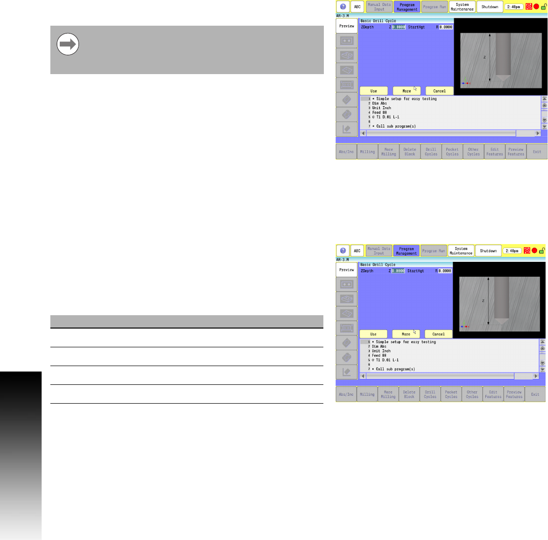
Basic Drill Cycle
Modal cycles remain active until canceled. Use Drilloff (G80) to cancel
drill, tap, and bore canned cycles.
Basic drilling cycle is generally used for center drilling or hole drilling
that does not require a pecking motion. It feeds from the start height
(R) to the specified hole depth (Z) at a given feedrate (F), then rapids
to the return height (P).
G-code format: G81
The P entry (return height) is optional, and you do not need
to provide it. If you do not specify P, the CNC sets it to R.
If P is provided, it must be greater than R, or an alarm is
given.
Field Code Description
ZDepth Z Absolute hole depth. (Required)
StartHgt R Initial Z start point, in rapid. (Required)
ReturnHgt P Z return point after hole depth, in rapid.
Feed F Feedrate