
Manual


Table Of Contents
- Controls of the 3500i
- Manual Information
- Introduction
- Machining Fundamentals
- Manual Data Input
- Tool Management
- 4.1 Tool Table
- 4.2 Tool Data
- Program Management
- Conversational Editing
- Programming: Canned Cycles, sub-programs
- 7.1 Explaining Basic Cycles
- Round/Chamfer
- Rapid
- Line
- Arc
- Dwell:
- Plane Selection
- Reference Point Return:
- Fixture Offset (Work Coordinate System Select):
- Unit (Inch/MM)
- Dimension (Abs/Inc)
- Absolute Zero Set
- Block Form
- Temporary Path Tolerance
- System Data
- FeedRate
- FeedRate (4th-Axis)
- Spindle RPM
- M - Functions
- Tool Definition and Activation
- Repeat Blocks
- 7.2 Canned Cycles
- 7.3 Probing Cycles
- 7.4 Sub-programs
- 7.1 Explaining Basic Cycles
- Drawing Programs
- Running a Program on the Machine
- CAM: Programming
- 10.1 CAM Programming
- CAM Mode
- Recommended CAM Programming Sequence
- CAM Mode Mouse Operations
- CAM Mode Screen
- Activating CAM Mode
- Creating a New Program
- Tool Path Data Input
- Quick Coordinate Entry
- Job Setup: Basic tab
- Job Setup: Advanced tab
- Comment Tab
- Block Form: Basic tab
- Comment Tab
- Drilling Cycle:
- Drilling dialogue:
- Mill Cycle
- Pocket Cycle
- Pocket Finish Cycles
- Engraving Cycle
- Program Directive
- Modifying Toolbar
- Viewing Tools
- CAM Mode buttons
- CAM Setup
- Geometry
- DXF Import Feature
- Modifying Tools
- Shapes
- Tool Table
- Tool Paths
- CAM Example 1
- CAM Example 2
- 10.1 CAM Programming
- G-Code Edit, Help, & Advanced Features
- 11.1 G-Code Program Editing
- 11.2 G-Code and M-Code Definitions
- 11.3 Edit Help
- 11.4 Advanced Programming
- SPEED
- M - Functions
- Order of Execution
- Programming Non-modal Exact Stop:
- In-Position Mode (Exact Stop Check):
- Contouring Mode (Cutting Mode) :
- Setting Stroke Limit:
- Return from Reference Point:
- Move Reference from Machine Datum:
- Modifiers
- Block Separators
- Tool Offset Modification
- Expressions and Functions
- System Variables
- User Variables
- Variable Programming (Parametric Programming)
- Probe Move (G31)
- Conditional Statements
- Short Form Addressing
- Logical and Comparative Terms
- File Inclusion
- 11.5 Four Axis Programming
- Software Update
- Off-Line Software
34 2 Machining Fundamentals
2.2 Manual Machine Positioning
2.2 Manual Machine Positioning
Jog Mode Moves
You can make or change jog moves when the CNC is in Manual Data
Input Mode, Teach Mode, or in the Tool Page; and the servos are on.
Changing the Jog Mode
Jog move modes, with the exception of Jog Rapid Mode, are
performed at the currently active feedrate. The CNC displays the
active Jog Mode in the Machine Status Display Area. See "Axis Jog
keys" on page 274.
In Manual Data Input Mode, Press the JOG key to select a jog feed
rate.
Pressing the JOG key continually cycles through the modes listed
above.
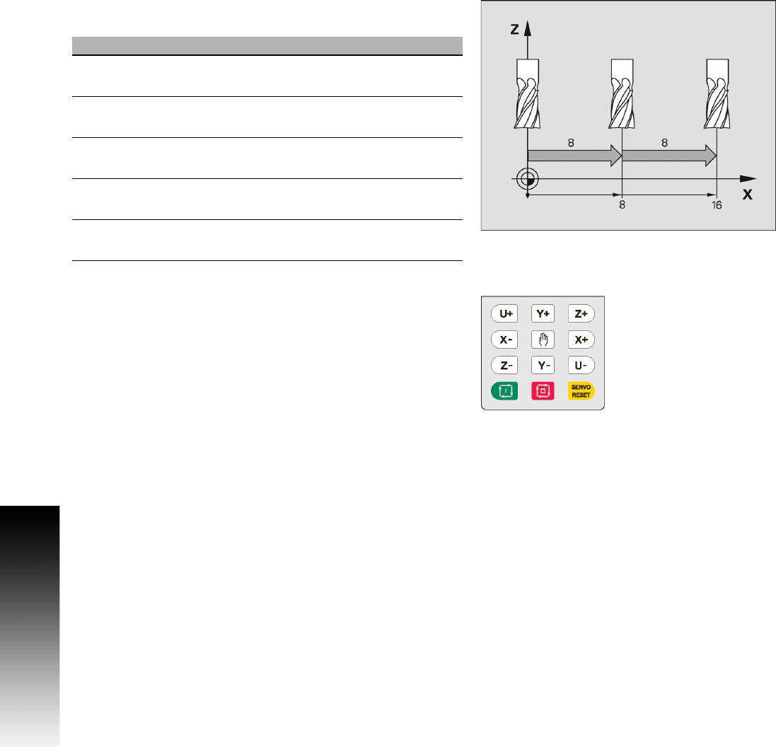
Incremental Moves
To make a jog increment move, press the JOG key to select a
Jog 100, Jog 10, or Jog 1 mode.
Press the Axis +/- keys for the desired axis to step the axis in the
corresponding direction at the designated resolution.
Continuous Moves
To manually position the machine using continuous movement,
press the JOG key to select either the Rapid or Feed Jog Modes.
Press the Axis +/- keys for the desired axis to move the axis in the
corresponding direction at the currently active feedrate (Feed Mode)
or at the machine rapid rate (Rapid Mode).
Jog Mode Description
Rapid Default rapid speed for continuous jogs. Actual
speed determined at machine setup.
Feed Continuous jog at feedrate determined at machine
setup.
Jog: 100 Conventional Jog Mode, increment set to 100 times
machine resolution.
Jog: 10 Conventional Jog Mode, increment set to 10 times
machine resolution.
Jog: 1 Conventional Jog Mode, increment set to actual
machine resolution.