
User guide


Acu-Rite Companies Inc.
ENC 250
™
MULTI-SECTION
6
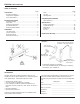
• Following the face alignment procedure, the top alignment
must be rechecked. Follow the previous steps placing the
indicator over each mounting hole.
• Recheck the scale face alignment at a second location to
insure the encoder is parallel. Use the leveling screws for
further alignment if necessary.
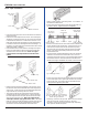
Move the indicator to a different
location on the face of the scale case
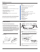
• Check for proper spacing between sections. Using a tape
measure, record the over all length of the mounted scale
sections (no end caps). Convert the length to millimeters
by multiplying by 25.4. If the sections are mounted
correctly, the last two digits of your measurement should
be very close to 40 mm; (e.g. 6640 mm, 8040 mm, 10840
mm etc.). If this distance is off by more than two
millimeters from nominal (e.g. 6637 mm, 6643 mm) shift
the location of the right end section to bring it within the
nominal distance.
End to end distance must be
xx40mm ± 2mm
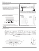
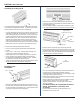
Scale face alignment
• To align the front face of the scale case to the axis travel,
first locate the high point. This is the TIR point furthest
away from the mounting surface along the axis travel.
Run an indicator along the front
face to locate the high point.
Mark the location, and set the
indicator to 0.000” [0.0mm]
• Loosen the next two fasteners to the right of the high point.
• Move indicator to the first hole location, insert two M3 x 25mm
SHSS (leveling set screws).
• Use the leveling screws to align the face to within [.012”]
.3mm to the high point along the axis travel and secure the
fastener.
• Move indicator to the next hole location, then loosen the
next fastener to the right. Align this location to within
[.012”] .3mm. Continue alignment with the remaining
fasteners.
• Return to the high point, and use the same procedure
working out to the left end.
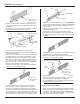
Dowel pin anchoring ...
[5/16”] 8mm Dowel
Pin (2)
Scale case holes are undersized to
insure accurate centering.
• Drill a [.302”] 7.7mm diameter hole through the dowel pin
hole locations at each end of the scale case [3/8”] 9.5mm
deep.
• Use a [.312] 8mm reamer to provide a press fit.
• Insert the dowel pins at each end, with the threaded hole
facing outward.
Example:
high point
Loosen next two
fasteners
Suggested first location
Suggested second location
Top surface
Threaded hole