
User guide


Acu-Rite Companies Inc.
ENC 250
™
MULTI-SECTION
• Before inserting the tape completely into the case, check
the tension value on the backside of the scale tape at the
anchor end. Check the value on the label attached to the
right end section, and verify that it is correct.
• The two M3 x 8mm Flat Head Socket Screws must be
removed from the scale anchor block. Continue pushing
the scale tape into the case until the anchor end is flush
with the left side of the case. Make sure that all the
scale tape retainer clips go into the T-slot. If the scale
tape can not be inserted completely by pushing at one end,
the scale tensioner may be pulled along the case with a
small steel ruler from the bottom of the scale case.
• Place the Scale Tensioner into the tee slot on the left end
of the scale case.
• Retrieve the scale tape from the carton. The scale tape is
shipped in a protective plastic coil. Do not uncoil the tape.
It should be uncoiled as it is inserted into the case. The
tape must be kept free of fingerprints and contaminants.
It is best to wear clean cotton gloves when handling it. If
necessary, the scale tape may be cleaned with cotton cloth
soaked in alcohol or acetone.
• Hook the boss on the scale tensioner through the square
hole in the scale tape to capture the tape and slide the
scale tensioner into the scale case. Note – the gold
rulings on the scale tape must face into the scale
cavity.
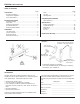
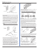
Scale Tape Installation
Scale Tensioner
End view of
tee slot
Scale Tape
Anchor block
Retainer clip
End view of
tee slot
Tape tension value
0.XXX mm
• Apply a small amount of silicone grease – as a sealant - to
the two M3 x 8mm FHSS.
• Insert the screws through the scale case and thread into
the anchor block. Tighten fasteners completely.
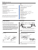
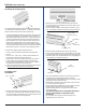
• Draw a line onto the front of the scale case at a distance of
[0.65”] 16.5mm from the left end. Similarly draw a line
onto the front of the scale case at a distance of [2.46”]
62.5mm from the right end. These are the end-of-travel
marks. The ends of the reading head must not travel
beyond those lines.
• Find the center distance between the two lines and draw
another line onto the front of the scale case. This line
represents the center of travel. The reading head must be
mounted so that it is centered under this line when the
machine carriage is located at the center of its axis travel.
[2.46”] 62.5mm
Equal Equal
[0.65”] 16.5mm
Left end of
travel mark
Center of
travel mark
Right end of
travel mark
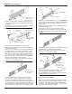
• Insert a lip seal into the front keyhole slot (the one closest
to the scale tape) until it protrudes at least 1/2” [12mm]
from the far side. Lip seals must be installed with the
keying features opposing each other.
• Similarly, insert the rear lip seal. Make sure that the lip
seals are not under excessive tension in the case.
Normally, the lip seal can be pulled through completely
with a pair of needle-nose pliers.
Lip seal keying feature
7
This view shows lip seal orientation.
It is not required for them to be inter
locked during installation.