MICRO-LINE ™ For Milling Applications REFERENCE MANUAL lllllllllllllllll ACU-RITE INCORPORATED One Precision Way • Jamestown,NY 14701 Readout Systems Precision Glass Scales
MLMmanual.QXD 2/12/02 5:01 PM Page 2 TABLE OF CONTENTS General Overview . . . . . . . . . . . . . . . . . . . . . . . . . . . . . . . . . . . . . . . . . . . 1 Preparation . . . . . . . . . . . . . . . . . . . . . . . . . . . . . . . . . . . . . . . . . . 2 Packing List . . . . . . . . . . . . . . . . . . . . . . . . . . . . . . . . . . . . . . 2 Warranty Records . . . . . . . . . . . . . . . . . . . . . . . . . . . . . . . . . . 2 Installing the Scales . . . . . . . . . . . . . . . . . . . . . . . . .
MLMmanual.QXD 2/12/02 5:01 PM Page 3 TABLE OF CONTENTS Bolthole Patterns. . . . . . . . . . . . . . . . . . . . . . . . . . . . . . . . . . . . . . 22 Creating . . . . . . . . . . . . . . . . . . . . . . . . . . . . . . . . . . . . . . 22, 23 Running . . . . . . . . . . . . . . . . . . . . . . . . . . . . . . . . . . . . . 24, 25 Troubleshooting Introduction. . . . . . . . . . . . . . . . . . . . . . . . . . . . . . . . . . . . . . . . . . 26 General . . . . . . . . . . . . . . . . . . . . . . . . . .
MLMmanual.QXD 2/12/02 5:01 PM Page 6 GENERAL Overview This manual will guide you through the installation, setup, and operation of the MICRO-LINE system. Use it to get your system up and running “out of the box” and as a quick reference guide for your day-to-day operations. Install the scales first, according to the instructions included in this manual. After the scales are in place, install the readout and then finish setting up the system.
MLMmanual.QXD 2/12/02 5:01 PM Page 7 GENERAL Preparation Packing List Verify that you have received all of the components for your system: • • • • Readout instructions Installation instructions Mounting arm MICRO-LINE scale(s) - Cable mounting hardware - Scale mounting hardware • Warranty card If a component is missing, contact your MICRO-LINE distributor immediately for replacement. Warranty Records Complete the warranty card included with your MICRO-LINE system.
MLMmanual.QXD 2/12/02 5:01 PM Page 10 GENERAL Installing the Scales Install the scales according to installation instructions found in this manual. These general installation instructions are found on page 40. Please read the instructions completely before beginning. If specific bracket kit instructions are included, they supersede instructions contained within this manual. Installing the Readout Follow the readout installation instructions that are included with your mounting arm bracket kit.
MLMmanual.QXD 2/12/02 5:01 PM Page 11 GENERAL Power Up Press the switch on the back of the readout to power up the system. A series of tests will check that the display, keypad, and memory are all working properly. If a problem is detected, an error code will appear on the screen. (Error messages and solutions are listed on pgs. 31 - 32.) It is important to note that the E1 message will appear every time you power up your system and does not indicate a problem.
MLMmanual.QXD 2/12/02 5:01 PM Page 14 SETUP Parameter Setup There are four parameters that you can define on your system: • • • • Display resolution (diS) Linear error compensation (LEC) Scale resolutions (rES) Scale count directions (Ct dir) Establish each setting the first time you power up the system. You can change the parameters later by returning to Setup and then using the ENTER key to scroll to the appropriate category.
MLMmanual.QXD 2/12/02 5:01 PM Page 15 SETUP Display Resolution The display resolution determines how detailed each scale’s position will be displayed on the readout. Use the setting that best suits each job. To change the display resolution: • Press the SETUP key. (“diS” will show on the display.) • Press the X, Y, or Z key for the display you want to change. For 10µm scales, the display resolution will toggle between 0.01 mm (0.0005”) and 0.02 mm (0.001”). For 5µm scales, it will toggle between 0.
MLMmanual.QXD 2/12/02 5:01 PM Page 18 SETUP Linear Error Compensation With MICRO-LINE, you can compensate for machine tool wear. If you know the linear error compensation (LEC) value in parts per million (PPM), you can enter it directly. If you don’t know the LEC, use the formula on the next page to determine the value for each axis. To change the linear error compensation: • Move to the “Linear Error Compensation” display in the Setup mode.
MLMmanual.QXD 2/12/02 5:01 PM Page 19 SETUP How to Determine the Linear Error Compensation Follow this procedure for each axis: • In the DRO mode. • Place a standard of known length on the table. Make sure it’s parallel with the table’s travel. • Put the readout in the absolute display mode (ABS/INCR key). • Using an edge finder or dial indicator, locate one end of the standard. • Press the ZERO key twice for the axis you are measuring. “0” should appear on the display.
MLMmanual.QXD 2/12/02 5:01 PM Page 22 SETUP Scale Resolution To ensure accurate readings, the scale resolution shown for each axis must correspond with the resolution of the scales on your machine. To change the scale resolution: • If necessary, choose “Scale Resolution” from the Setup menu. (Press SETUP and then the ENTER key until the screen appears). • Press the X-axis key until the appropriate resolution appears. Choose 0.01 mm for 10µm (0.0005”) scales and 0.005 mm for 5µm (0.
MLMmanual.QXD 2/12/02 5:01 PM Page 23 SETUP Count Direction Use the count direction setting to define the positive counting direction for each scale. The direction will be displayed as a “1” or a “2” (the numbers are not assigned to a particular direction). You only need to change the count direction if the scale is counting in the negative direction during a positive table move, or vice versa. Refer to Conventions on pg. 37 for more guidelines.
MLMmanual.QXD 2/12/02 5:01 PM Page 26 SETUP Testing the Scales Follow these steps to confirm that the scale has been installed properly. The Counting Test will confirm the scale’s electrical operation, and the Repeatability Test will check the installation integrity. Counting Test • Move the table along each axis, one at a time. Check that the readout correctly displays the table’s movement. If it doesn’t, then the scale resolution you selected may not be accurate. Refer to Scale Resolution on pg.
MLMmanual.QXD 2/12/02 5:01 PM Page 27 O P E R AT I O N Setting the Datum (Absolute Zero) MICRO-LINE allows you to measure both absolute and incremental dimensions. A dimension measured from the point you define as the datum is an absolute dimension. A dimension measured from any other point on your print is an incremental dimension. Datum, also known as absolute zero or workpiece zero, is the reference point from which MICRO-LINE will base all of your part’s coordinates.
MLMmanual.QXD 2/12/02 5:01 PM Page 30 OPERATION If you are using 5µm (0.0002”) scales (international units only), MICRO-LINE can recall your last datum position each time you power up the system. Refer to pg. 38 for the proper procedure. To set the datum at the tool’s current position: • Position the workpiece on the table. Move the table until the tool is centered on the edge of the workpiece at the location where you would like to establish the datum.
MLMmanual.QXD 2/12/02 5:01 PM Page 31 OPERATION Example: Absolute Dimensions Let’s say that your print looks like this: Datum Here is how you would drill the holes using absolute dimensions. Notice that all of the dimensions are measured from the point that was established as datum (0, 0, 0). • Check that “ABS” is selected on the DRO display (press the ABS/INCR key, if necessary).
MLMmanual.QXD 2/12/02 5:01 PM Page 34 OPERATION Incremental Dimensions As described earlier, incremental dimensions are measured from the current tool position to the next. If the tool is currently at 2” and you want to move an additional 3.125”, you would select the incremental mode, zero out the axis, and move the table until the display reads 3.125. An example of how to measure using incremental dimensions is shown on the next page.
MLMmanual.QXD 2/12/02 5:01 PM Page 35 OPERATION Example: Incremental Dimensions Let’s say that your print looks like this: Hole 1 is an absolute dimension (measured from the datum), while Holes 2 and 3 are measured incrementally. By putting MICRO-LINE in the incremental mode for the last two holes, you can measure their distances just as the print specifies, without any calculations. 1. Press the ABS/INCR key until “ABS” is selected on the DRO display.
MLMmanual.QXD 2/12/02 5:01 PM Page 38 OPERATION 6. Now repeat the process for the third hole. Press the ZERO key for the X-axis to measure from your tool’s current position. 7. Move the table until X = 2.00” and Y = 0.000”. Drill Hole 3. Using Incremental Presets In the standard incremental mode, you would reset the display at “0” and move the table until the scale counts up to the point you want to reach. With the preset feature, you enter the distance you want to move first, and then count down to 0.
MLMmanual.QXD 2/12/02 5:01 PM Page 39 OPERATION Example: Incremental Presets Datum Hole 1 is an absolute dimension because it’s measured from datum. Holes 2 and 3 are incremental dimensions (measured from one hole to the next) that you can preset. 1. Press the ABS/INCR key until “ABS” is selected on the DRO display. Also check that the system is in the “inches” mode (the MM key should not be lit up). 2. For Hole 1, move the table until X = 2.00” and Y = 1.5”. Drill Hole 1. 3.
MLMmanual.QXD 2/12/02 5:01 PM Page 42 OPERATION Centerline With MICRO-LINE, you can find the centerline (midpoint) between any two positions on your part. You can establish centerline as your datum by using absolute dimensions or you can create a centerline using incremental measurements without affecting your current datum. Refer to “Setting the Datum (Absolute Zero)” on pg. 12. Setting the Datum on a Centerline 1. Press the ABS/INCR key until ABS is selected. 2. Move the table to the first location.
MLMmanual.QXD 2/12/02 5:01 PM Page 43 OPERATION Example: Setting the Datum on a Centerline Here’s how you would establish the datum on the centerline of the part shown: 1. Using the ABS/INCR key, select the absolute (ABS) mode. Check that the proper measurement (inch or mm) is selected. 2. Rest the indicator against any point on the left or right side of the circle. (In graphic 1 above, we started on the left side.) Press the ZERO key for the X-axis twice. 3.
MLMmanual.QXD 2/12/02 5:01 PM Page 46 OPERATION Locating Centerline Using Incremental Dimensions 1. Press the ABS/INCR key to select the incremental display mode. 2. Move the table to the first location. 3. Press the ZERO key for the appropriate axis. Doing so will zero the current position. 4. Move the table to the second location along the same axis. 5. Press the C/L (centerline) key. Dashes will flash on the screen. 6. Press the appropriate key (X, Y, or Z) for the axis you’re measuring. 7.
MLMmanual.QXD 2/12/02 5:01 PM Page 47 OPERATION Bolthole Patterns Creating a Bolthole Pattern Hole 1 A bolthole pattern is defined by its number of holes (up to 99), center point, radius, and start angle. MICRO-LINE will automatically position “Hole 1” at the start angle and space the holes equally throughout the pattern. To create a bolthole pattern: 1. Press the BOLT DEF key. "HOLES" will appear on the X-axis display. 2. Enter the number of holes (1-99) in the pattern. Press the ENTER key. 3.
MLMmanual.QXD 2/12/02 5:01 PM Page 50 OPERATION 6. Press the Y key. Enter the bolthole pattern’s center point on the Y-axis. Use a decimal point and minus (-) sign if necessary. 7. Press the ENTER key. 8. Press the ENTER key again. “Radius” will appear. 9. Enter the radius of the circle pattern. Press ENTER. 10. Press ENTER again. "START" will appear on the X-axis display. 11. Enter the start angle of the first hole in the bolthole pattern. (0 degrees is at the 3 o’clock position.
MLMmanual.QXD 2/12/02 5:01 PM Page 51 OPERATION Running a Bolthole Pattern When you run a bolthole pattern, MICRO-LINE always assumes that you want to start with the first hole. It will display “Hole 1,” and then the distance to the hole from your tool’s current position. Move the table until it reaches 0, 0. After you’ve drilled the hole, press the BOLT USE key again, and “Hole 2” will appear. Move the table to “0,” drill the hole and continue with the rest of the pattern.
MLMmanual.QXD 2/12/02 5:01 PM Page 52 OPERATION Note: To select a different hole in the pattern, press the BOLT USE key and immediately press the number of the hole you want to mill. Press “2” on the keypad for Hole 2, “3” for Hole 3, etc. The holes are numbered counter-clockwise from the start angle. You can also scroll through the series of holes by pressing the BOLT USE key repeatedly.
MLMmanual.QXD 2/12/02 5:01 PM Page 49 TROUBLESHOOTING Troubleshooting Introduction Refer to this troubleshooting guide whenever you have questions or concerns about the operation of the MICRO-LINE system. This guide is arranged in three columns entitled Symptom, Probable Cause and Recommended Corrective Action. The symptoms are listed in the order of the most common, easiest to check, and least expensive to correct. First locate the symptom that best describes the problem you are trying to solve.
MLMmanual.QXD 2/12/02 5:01 PM Page 48 TROUBLESHOOTING Symptom Probable Cause Screen is blank No power to the readout Recommended Corrective Action Check that the power switch on the back of the console is “on.” Check that the readout’s power cord is properly connected to the power supply. Check the fuse. (Located above the power switch). Check that the power source meets the specifications required by your system (pg. 33).
MLMmanual.QXD 2/12/02 5:01 PM Page 45 TROUBLESHOOTING Recommended Corrective Action Symptom Probable Cause Dashes appear on screen (cont’d) Display overflow Move the table toward the “0” position. As the scale counts down, the display will show the correct position. Error message (E1) appears Power loss occurred This is a normal message at power up. If the message appears at any other time during operation, a problem may have occurred. Refer to pg. 31 for details.
MLMmanual.QXD 2/12/02 5:01 PM Page 44 TROUBLESHOOTING Recommended Corrective Action Symptom Probable Cause Scale won’t count Loose cable Check that the scale cable is securely connected to the readout. Wrong input Check that the scale cable is connected to the correct input on the back of the readout. Refer to the readout installation instructions. Scale not installed properly Check the scale and reading head for proper installation (refer to scale installation instructions).
MLMmanual.QXD 2/12/02 5:01 PM Page 41 TROUBLESHOOTING Recommended Corrective Action Symptom Probable Cause Setup does not save values Improper procedure Press the ENTER key after each value is entered into a Setup screen. If you press another key instead, the new value will not be saved. Refer to pgs. 5 - 10 for proper procedures. Numbers don’t appear/are faded on the display LED failure Turn the system “off” and then “on” again, using the switch on the back of the readout.
MLMmanual.QXD 2/12/02 5:01 PM Page 40 TROUBLESHOOTING Error Messages (General) When MICRO-LINE is powered up, it will run a series of tests to ensure that the software is working properly. If an error message appears, refer to the charts on this page and the next for a diagnosis and solution. E1 A power loss has occurred. This message will appear every time you power up the system and can be cleared by pressing the CLEAR key.
MLMmanual.QXD 2/12/02 5:01 PM Page 37 TROUBLESHOOTING Error Messages (Keypad Test) The messages below indicate that a problem was found during the keypad test at startup. If an error message appears, turn the system off, press the appropriate key to release it back into position, and then restart the system. (Or you can press the CLEAR key to clear the error message.) If the key does not work during normal operation, contact your distributor for repair/replacement procedures.
MLMmanual.QXD 2/12/02 5:01 PM Page 36 REFERENCE Electrical Specifications Follow these specifications when installing your MICRO-LINE system.
MLMmanual.QXD 2/12/02 5:01 PM Page 33 REFERENCE Factory Default Settings Display Resolution High (0.0005"/0.01 mm for 10µm scale) Linear Error Compensation 0 parts per million Scale Resolution 0.0005”/0.
MLMmanual.QXD 2/12/02 5:01 PM Page 32 REFERENCE Keypad Here’s an overview of the MICROLINE keypad. Each key’s function is described below. X, Y, Z Correspond with the scales on the X-, Y-, and Z-axes. Used to specify a change to a particular axis. ZERO Three keys reset the incremental or absolute display position at “0” for the corresponding axis. ABS/INCR Used to switch between absolute (ABS) and incremental (INCR) measurements. The active mode will be displayed at the top of the DRO display.
MLMmanual.QXD 2/12/02 5:01 PM Page 29 REFERENCE 36 BOLT DEF Used to create a bolthole pattern. BOLT USE Used to run a bolthole pattern. CLEAR Acts as backspace key during numeric entry; otherwise, it clears or cancels the last operation. ENTER Completes numeric operations; selects next parameter in SETUP or BOLT DEF operations. ± Changes the sign of the entered value from positive(+) to negative(-) or vise versa. Numbers are positive unless a (-) appears in front of them. .
MLMmanual.QXD 2/12/02 5:01 PM Page 28 REFERENCE Conventions This section identifies the standard conventions that apply to your MICRO-LINE system. DRO Mode The MICRO-LINE system is considered to be in the DRO (digital readout) mode when the X- and Y-axes positions are displayed for a 2-axes system, and the X-, Y-, and Z-axes positions are displayed on a 3-axes system. Count Direction MICRO-LINE uses positive and negative numbers to determine the posi- tion of the table and tool on each axis.
MLMmanual.QXD 2/12/02 5:01 PM Page 25 REFERENCE Recalling the Last Datum Setting For International Units If you are using 5µm MICRO-LINE scales, MICRO-LINE can retrieve your last datum setting when you power up your system. This feature is especially useful when you have to shut down the system in the middle of a job, or if a power interruption occurs. When power is restored, MICRO-LINE will use Position-TracTM technology to read the scales’ reference marks and recall the datum within seconds.
MLMmanual.
MLMmanual.QXD 2/12/02 5:01 PM Page 21 SCALE INSTALLATION General Installation Instructions for the Scale Specific instructions may be included that will supersede this section. Please do not expose the scale to the following: Installation Brackets • • 40 Installation brackets and tools are already included with each system. Your Authorized ACU-RITE Distributor can assist you in selecting brackets and tools for your installation.
MLMmanual.QXD 2/12/02 5:01 PM Page 20 SCALE INSTALLATION Introduction The MICRO-LINE precision glass scale provides the accuracy and reliability of an ACU-RITE measuring system. Features and options include: • • • • • • • Digital resolutions of 5 or 10µm. Accuracy Grade of ± 10µm/1000mm. Home reference signals on international units only. Braided cables in 10ft., 15ft., or 20ft. lengths.
MLMmanual.QXD 2/12/02 5:01 PM Page 17 SCALE INSTALLATION Mounting Preparation • • • • • Understand your mounting requirements. Mount with lipseals down and away from the work area. Brackets should be kept as short and rigid as possible. Clean all mounting surfaces. Ensure the correct length scale is being used for the total machine travel. Do not remove alignment brackets until instructed. Never mount with lipseals upward or toward work area. Equipment travel must not exceed scale measuring length.
MLMmanual.QXD 2/12/02 5:01 PM Page 16 SCALE INSTALLATION Mounting Information • • Mount the scale close to machine guide ways to ensure system accuracy. Follow kit instructions when using an ACU-RITE bracket kit. Gap .005 - .180 max. • • • A gap greater than .18” between the reading head and mounting surface requires a spacer or bracket. Reading head leveling set screws are provided to adjust the gap between the reading head and mounting surface. Tolerances of .
MLMmanual.
MLMmanual.
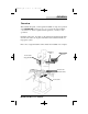
MLMmanual.QXD 2/12/02 5:01 PM Page 9 SCALE INSTALLATION Installation Procedure These steps apply to typical mounting conditions. Although this may not pictorially represent your application, your installation procedure should follow these steps. ACU-RITE bracket kit instructions supersede this section. • • Adjust drill depths and fastener lengths as required. Contact your Authorized ACU-RITE Distributor if assistance is required. First Steps: 1. Move the axis to its center of travel. 2.
MLMmanual.QXD 2/12/02 5:01 PM Page 8 SCALE INSTALLATION 7. Align to within .010” TIR to axis of travel and mark the second end mounting hole. Remove scale, drill and tap correct hole size. 8. Attach the scale and align to within .010” TIR to axis of travel. 9. Top mounting requires the top surface to be indicated to within .010” TIR over each mounting hole. Mark remaining hole locations. Remove scale, drill and tap remaining holes. Attach the scale and align to within .010” TIR to axis of travel. 10.
MLMmanual.QXD 2/12/02 5:01 PM Page 5 SCALE INSTALLATION 13. Move the axis to align reading head mounting holes. 14. A gap must exist between the reading head and the mounting surface. 15. Adjust the leveling screws, using a .001" -.003" feeler gage (or shim) between the leveling screw and the mounting surface. Adjust the leveling screw until a slight drag is felt on the feeler gage. Repeat this for each leveling screw, 3 total. 16. Evenly tighten the two 8-32 SHCS to secure the reading head. 17.
MLMmanual.QXD 2/12/02 5:01 PM Page 4 WARRANTY Hassle-Free Warranty ACU-RITE readouts and precision glass scales are warranted to the end user against defects in material and workmanship and against any damage that occurs to the product within three (3) years from the original purchase date.
MICRO-LINE ™ For Milling Applications REFERENCE MANUAL lllllllllllllllll ACU-RITE INCORPORATED One Precision Way • Jamestown,NY 14701 Readout Systems Precision Glass Scales