Installation, Operating and Servicing Instructions E-tech S 160 / 240 / 290 / 380 excellence in hot water 03/02/2005 - 66401700.
INDEX INTRODUCTION People who should read these instructions Symbols Warnings DESCRIPTION Overview Operating principle Construction features INTRODUCTION 1 1 1 1 2 2 2 2 PEOPLE WHO SHOULD READ THESE INSTRUCTIONS These instructions are intended for: - specifying engineers - the installing engineers - end-users - servicing engineers SYMBOLS The following symbols are used in these instructions: TECHNICAL SPECIFICATIONS Dimensions General features Maximum operating conditions Domestic hot water performa
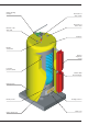
DESCRIPTION OVERVIEW CONSTRUCTION FEAURES • Combination boiler (central heating and domestic hot water). • TANK-IN-TANK indirect storage type domestic hot water production. • The central heating connections are designed so that they can be connected in all three directions, this means that the boiler can be installed against a wall or in a corner without having to leave any free space (see page 6).
DESCRIPTION Central heating flow pipe Domestic hot water return Domestic hot water outlet Domestic cold water inlet Insulation Primary safety valve Primary expansion vessel Low water pressure switch Tank-in-Tank heat exchanger Heating return Primary circuit Control thermostat Heating resistors Drain cock 3
TECHNICAL SPECIFICATIONS DIMENSIONS The units are delivered fully assembled, tested and packed on a timber base with shockproof edges and protected by heat-shrunk plastic film. On reception and after unpacking, check the equipment for domage. For transport purposes, refer to the weight and dimensions give below.
TECHNICAL SPECIFICATIONS MAXIMUM OPERATING CONDITIONS Maximum operating pressure (tank full of water) - Primary circuit: 3 bar - Secondary circuit: 10 bar Test pressure (tank full of water) - Primary circuit: 4.
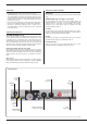
INSTALLATION BOILER ROOM HEATING CONNECTION Important The drain cock (8) and safety valve (2) must be connected to the waste water disposal system. • Keep vents free at all times. • Do not store inflammable products in the boiler room. • Do not store corrosive products near the boiler, such as paints, solvents, chlorine, salt, soap and other cleaning products.
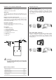
INSTALLATION DOMESTIC HOT WATER CONNECTION CONTROLLER KITS Pressure reducer KIT 1: ACV 13.00 / Basic If the water mains pressure is greater than 6 bar, a pressure reducer calibrated to 4.5 bar must be fitted. Basic kit for regulating initial flow temperature according to weather conditions. It comprises: a temperature regulator with analogue clock, wall-mounted water temperature sensor (-30/130 °C), external sensor (-30/50 °C), 3-pin servomotor SQY 31 230 V and an intermediate base.
8 r 230 - 240 V ac bk- black br- brown r-red w-white y- yellow o - orange b - blue v - violet p - pink gr - grey CABLE COLOUR CODES 3 amp MCB bk b C 1 2 v b r r 2 Lockout Indicator C 1 o b Remove Link If Clock Used w o o C o Switch Indicator Panel Heating Switch 1 High Temp Limit (Auto Reset) 1.2. p 2.2. y o Panel Stage 2 Switch Panel Stage 1 Switch w 6 Switch Indicator Remove Link If Option Used 5 Optional External Heating Clock or Stat Boiler Stat (78 - 53°C) 1.
r 230 - 240 V ac bk- black br- brown r-red w-white y- yellow o - orange b - blue v - violet p - pink gr - grey CABLE COLOUR CODES 3 amp MCB bk 2 1 bk Panel On Off Switch b C 1 v b r r 2 Lockout Indicator C 1 o Water Pressure Switch b Remove Link If Clock Used w o o C o Switch Indicator Panel Heating Switch 1 High Temp Limit (Auto Reset) br 1.2. p 2.2.
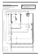
INSTALLATION Connecting the accessories Electrical terminal block The electrical accessories are connected to the numbered terminals on the control terminal block as shown on the control wiring diagram. Power wiring diagram • For the mono phase model (In top of the page 11) • For the tri phase model (In bottom of the page 11) Power terminal block Magneto-therminal circuit breaker Electrical safety devices • The boiler must be effectively earthed.
INSTALLATION To Control Circuit MCB L N 3 x Blue 3 x Blue 3 x Red 3 x Red E-Tech Single Phase Power Wiring Green / Yellow Stage 1 Power Relay 1 Stage 1 Power Relay 2 Stage 2 Power Relay 1 To Boiler Body To Control Circuit MCB L1 L2 L3 Green / Yellow 4 x Red E-Tech S Tri Phase Power Wiring 4 x Blue 4 x Black 4 x Orange N Blue Red Black Orange Stage 1 Power Relay 1 Blue Red Black Orange Stage 1 Power Relay 2 Blue Red Black Orange Stage 2 Power Relay 1 Blue Red Black Orange Stage 2 P
COMMISSIONING FILLING THE DOMESTIC HOT WATER AND HEATING CIRCUITS 1. Fill the domestic hot water circuit and bring it up to pressure IMPORTANT The hot water tank must be pressurised before the heating circuit is filled. 2. Fill the central heating circuit making sure that any air in the upper part of the boiler and any air in the system is bled. 3. Remove the front of the boiler. 4.
MAINTENANCE SERVICE INTERVALS ACV recommend that boilers should be serviced at least once a year. This servicing work should be carried out by a competent technician. 1 1 SERVICING THE BOILER 1. Set the on/off switch on the control panel to the OFF pos tion and switch the power off from the external box. 2. Remove the top panel and the front and carry out a visual inspection of the boiler looking out for any leaking water. 3. Inspect the wiring looking for any sign of overheating. 4.
USER GUIDE USING THE BOILER Your system should be serviced at least once year by a qualified engineer. If the boiler is subject to heavy use, it may require servicing more than once a year - consult your service engineer for advice. 7 - Safety thermostat When the temperature in the boiler exceeds 103 °C, the manually reset safety thermostat is started up. 8 - Boiler shutdown indicator light This light is lit when the safety thermostat starts up or when the water pressure in the boiler is too low.
USER GUIDE BOILER SHUTDOWN If the red light on the control panel lights up, this indicates an operating fault. 1. Check the boiler pressure, it should be between 1 and 2 bar depending on the height of the building. 2. Once you have checked the pressure, wait until the boiler has cooled down before resetting the safety thermostat. 3. Unscrew the safety thermostat’s protective cap. 4. Restart the thermostat using a blade end. 5. If the system shuts down again, please inform the installing engineer.
NOTE 16
www.acv-world.com excellence in hot water INTERNATIONAL FRANCE SLOVAK REPUBLIC ACV international n.v KERKPLEIN, 39 B-1601 RUISBROEK - BELGIUM TEL.: +32 2 334 82 20 FAX: +32 2 378 16 49 E-MAIL: international.info@acv-world.com ACV FRANCE sa 31, RUE AMPERE - Z.I MI - PLAINE F-69680 CHASSIEU - FRANCE TEL.:+33 4 72 47 07 76 FAX:+33 4 72 47 08 72 E-MAIL: france.info@acv-world.com ACV SLOVAKIA s.r.o. PLUHOVÁ 49 831 04 BRATISLAVA - SLOVAK REPUBLIC TEL.