
Specifications


8
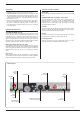
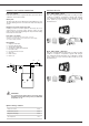
INSTALLATION
ELECTRICAL CONNECTIONS
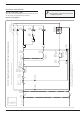
Control circuit power supply
The control circuit is automatically powered from the power circuit. It is
also protected by a magneto-thermal circuit breaker.
Control wiring diagram
It is important to switch the boiler off before
carrying out any work.
1
3
4
5
6
7
8
9
C
2
C
2.1. 2.2.
1.1. 1.2.
A1 A2
1
2
1
10 11
12 13
14 15
18
19
br
br
v
r
r
o
o
w
o
w
o
r
w
pgr
w
o
y
w
v
r
y
r
r
r
o
21
bk
b
b
b
b
b
b
b
b
C
1
2
20
o
bk
E-Tech `S` Single Phase Control Circuit - With shunt circuit (factory wired)
CABLE COLOUR CODES
bk- black
br- brown
r-red
w-white
y- yellow
o - orange
b - blue
v - violet
p - pink
gr - grey
All bold numbers indicate a DIN rail terminal connection
Boiler Stat
(78 - 53°C)
PLEASE NOTE: Due to the potential risk of ELECTRIC SHOCK this section of the manual is intended for use
by a service engineer or qualified electrician, not the user
230 - 240 V ac
3 amp
MCB
Panel
On Off
Switch
High Temp
Limit
(manual reset)
Water
Pressure
Switch
Optional
Internal Or
External
Boiler Control
Clock
High Temp
Limit
(Auto Reset)
Boiler Stat
(85 - 60°C)
Panel
Stage 1
Switch
Panel
Stage 2
Switch
Optional Internal -
External Clock Supply
Circulating
Pump
Stage 1
Power
Relay 1
Stage 1
Power
Relay 2
Stage 2
Power
Relay 1
Stage 1
Delay
Timer
Heating Valve
(Not Supplied)
Panel
Heating
Switch
Switch
Indicator
Switch
Indicator
Switch
Indicator
Remove Link If
Option Used
Optional
External Heating
Clock or Stat
M
Switch
Indicator
Lockout
Indicator
Remove Link If
Clock Used
r