
Data Sheet


© 2005 Microchip Technology Inc. DS21984A-page 13
MCP73831
6.0 APPLICATIONS
The MCP73831 is designed to operate in conjunction
with a host microcontroller or in a stand-alone applica-
tion. The MCP73831 provides the preferred charge
algorithm for Lithium-Ion and Lithium-Polymer cells
constant current followed by constant voltage.
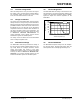
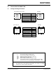
Figure 6-1 depicts a typical stand-alone application
circuit, while Figures 6-2 and 6-3 depict the
accompanying charge profile.
FIGURE 6-1: Typical Application Circuit.
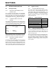
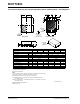
FIGURE 6-2: Typical Charge Profile
(180 mAh Battery).
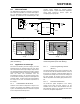
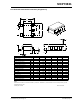
FIGURE 6-3: Typical Charge Profile in
Thermal Regulation (1000 mAh Battery).
6.1 Application Circuit Design
Due to the low efficiency of linear charging, the most
important factors are thermal design and cost, which
are a direct function of the input voltage, output current
and thermal impedance between the battery charger
and the ambient cooling air. The worst-case situation is
when the device has transitioned from the
Preconditioning mode to the Constant-Current mode.
In this situation, the battery charger has to dissipate the
maximum power. A trade-off must be made between
the charge current, cost and thermal requirements of
the charger.
6.1.1 COMPONENT SELECTION
Selection of the external components in Figure 6-1 is
crucial to the integrity and reliability of the charging
system. The following discussion is intended as a guide
for the component selection process.
6.1.1.1 Current Programming Resistor
(R
PROG
)
The preferred fast charge current for Lithium-Ion cells
is at the 1C rate, with an absolute maximum current at
the 2C rate. For example, a 500 mAh battery pack has
a preferred fast charge current of 500 mA. Charging at
this rate provides the shortest charge cycle times
without degradation to the battery pack performance or
life.
6.1.1.2 Thermal Considerations
The worst-case power dissipation in the battery
charger occurs when the input voltage is at the
maximum and the device has transitioned from the
Preconditioning mode to the Constant-Current mode.
In this case, the power dissipation is:
STAT
V
DD
V
SS
PROG
V
BAT
+
-
Single
Li-Ion
Cell
4
MCP73831
5
3
1
C
IN
Li-Ion Battery Charger
2
R
PROG
R
LED
C
OUT
REGULATED
WALL CUBE
LED
0.0
1.0
2.0
3.0
4.0
5.0
6.0
0
20
40
60
80
100
120
140
160
180
Time (S)
Battery Voltage (V)
0
20
40
60
80
100
120
Charge Current (mA)
MCP73831-2AC/IOT
V
DD
= 5.2V
R
PROG
= 10k
Ω
0.0
1.0
2.0
3.0
4.0
5.0
6.0
0
30
60
90
120
150
180
210
240
Time (S)
Battery Voltage (V)
0
100
200
300
400
500
600
Charge Current (mA)
MCP73831-2AC/IOT
V
DD
= 5.2V
R
PROG
= 2k
Ω