
Datasheet

SCL
SDA
t
LOW
t
R
t
F
t
HDSTA
t
HDSTA
t
HDDAT
t
BUF
t
SUDAT
t
HIGH
t
SUSTA
t
SUSTO
P S S P
ADS1113
ADS1114
ADS1115
www.ti.com
SBAS444B –MAY 2009–REVISED OCTOBER 2009
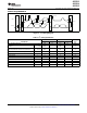
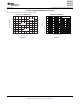
TIMING REQUIREMENTS
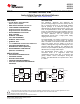
Figure 1. I
2
C Timing Diagram
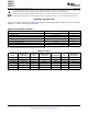
Table 1. I
2
C Timing Definitions
FAST MODE HIGH-SPEED MODE
PARAMETER MIN MAX MIN MAX UNIT
SCL operating frequency f
SCL
0.01 0.4 0.01 3.4 MHz
Bus free time between START and STOP
t
BUF
600 160 ns
condition
Hold time after repeated START condition.
t
HDSTA
600 160 ns
After this period, the first clock is generated.
Repeated START condition setup time t
SUSTA
600 160 ns
Stop condition setup time t
SUSTO
600 160 ns
Data hold time t
HDDAT
0 0 ns
Data setup time t
SUDAT
100 10 ns
SCL clock low period t
LOW
1300 160 ns
SCL clock high period t
HIGH
600 60 ns
Clock/data fall time t
F
300 160 ns
Clock/data rise time t
R
300 160 ns
Copyright © 2009, Texas Instruments Incorporated Submit Documentation Feedback 5
Product Folder Link(s): ADS1113 ADS1114 ADS1115