
Datasheet

20
9596A–AT42–10/10
AT42QT1070
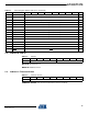
5.4 Address 2: Detection Status
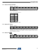
CALIBRATE: This bit is set during a calibration sequence.
OVERFLOW: This bit is set if the time to acquire all key signals exceeds 8 ms.
TOUCH: This bit is set if any keys are in detect.
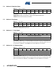
5.5 Address 3: Key Status
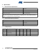
KEY0 – 6: bits 0 to 6 indicate which keys are in detection, if any. Touched keys report as 1,
untouched or disabled keys report as 0.
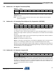
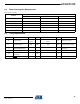
5.6 Address 4 – 17: Key Signal
KEY SIGNAL: addresses 4 – 17 allow key signals to be read for each key, starting with key 0.
There are two bytes of data for each key. These are the key’s 16-bit key signals which are
accessed as two 8-bit bytes, stored MSByte first. These addresses are read-only.
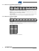
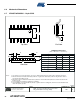
5.7 Address 18 – 31: Reference Data
REFERENCE DATA: addresses 18 – 31 allow reference data to be read for each key, starting
with key 0. There are two bytes of data for each key. These are the key’s 16-bit reference data
which is accessed as two 8-bit bytes, stored MSByte first. These addresses are read-only.
Table 5-4. Detection Status
Addressb7b6b5b4b3b2b1b0
2
CALIBRATE OVERFLOW
–––––TOUCH
Table 5-5. Key Status
Address b7 b6 b5 b4 b3 b2 b1 b0
3 Reserved KEY6 KEY5 KEY4 KEY3 KEY2 KEY1 KEY0
Table 5-6. Key Signal
Address b7 b6 b5 b4 b3 b2 b1 b0
4 MSByte OF KEY SIGNAL FOR KEY 0
5 LSByte OF KEY SIGNAL FOR KEY 0
6 – 17 MSByte/LSByte OF KEY SIGNAL FOR KEYS 1 – 6
Table 5-7. Reference Data
Address b7 b6 b5 b4 b3 b2 b1 b0
18 MSByte OF REFERENCE DATA FOR KEY 0
19 LSByte OF REFERENCE DATA FOR KEY 0
20 – 31 MSByte/LSByte OF REFERENCE DATA FOR KEYS 1 – 6