
Datasheet

22
9596A–AT42–10/10
AT42QT1070
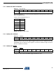
5.11 Address 53: FastOutDI/Max Cal/Guard Channel
FO: Fast Out DI – when bit 5 is set then a key filters out with an integrator of 4. Could have a DI
in of 100 but filter out with DI of 4 (global setting for all keys).
MAX CAL: if this bit is clear then all keys recalibrate after a Max On Duration timeout, otherwise
only the key with the incorrect timing gets recalibrated.
GUARD CHANNEL: bits 0 – 3 are used to set a key as the guard channel (which gets priority
filtering). Valid values are 0 – 6, with any larger value disabling the guard key feature.
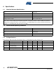
5.12 Address 54: Low Power (LP) Mode
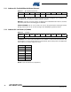
LP MODE: this 8-bit value determines the number of 8 ms intervals between key
measurements. Longer intervals between measurements yield a lower power consumption but
at the expense of a slower response to touch.
Default: 2 (16 ms between key acquisitions)
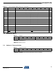
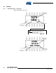
Table 5-11. Max On/Guard Channel
Address b7 b6 b5 b4 b3 b2 b1 b0
53 – FO MAX CAL GUARD CHANNEL
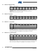
Table 5-12. LP Mode
Address b7 b6 b5 b4 b3 b2 b1 b0
54 LOW POWER MODE
Setting Time
0 8ms
1 8ms
2 16 ms
3 24 ms
4 32 ms
...254 2.032s
255 2.040s