Adafruit DC and Stepper Motor HAT for Raspberry Pi Created by lady ada Last updated on 2019-06-19 04:39:39 PM UTC
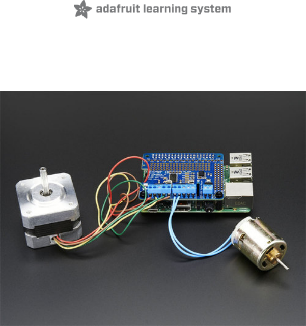
Overview Let your robotic dreams come true with the new DC+Stepper Motor HAT from Adafruit. This Raspberry Pi add-on is perfect for any motion project as it can drive up to 4 DC or 2 Stepper motors with full PWM speed control. Raspberry Pi and motors are not included Since the Raspberry Pi does not have a lot of PWM pins, we use a fully-dedicated PWM driver chip onboard to both © Adafruit Industries https://learn.adafruit.
control motor direction and speed. This chip handles all the motor and speed controls over I2C. Only two GPIO pins (SDA & SCL) are required to drive the multiple motors, and since it's I2C you can also connect any other I2C devices or HATs to the same pins. In fact, you can even stack multiple Motor HATs, up to 32 of them, for controlling up to 64 stepper motors or 128 DC motors - just remember to purchase and solder in a stacking header instead of the one we include.
We even had a little space so we added a polarity protection FET on the power pins and a bit of prototyping area. And the HAT is assembled and tested here at Adafruit so all you have to do is solder on the included 2x20 plain header and the terminal blocks. Lets check out these specs again: 4 H-Bridges: TB6612 chipset provides 1.2A per bridge (3A brief peak) with thermal shutdown protection, internal kickback protection diodes. Can run motors on 4.5VDC to 13.5VDC.
Comes with an assembled & tested HAT, terminal blocks, and 2x20 plain header. Some soldering is required to assemble the headers on. Stacking header not included, but we sell them in the shop so if you want to stack HATs, please pick one up at the same time. (http://adafru.it/2223) Raspberry Pi and motors are not included but we have lots of motors in the shop and all our DC motors, and stepper motors work great. © Adafruit Industries https://learn.adafruit.
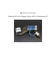
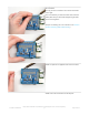
Assembly Solder on Headers and Terminal Block Before we can motorin' there's a little soldering to be done. This step will attach the 2x20 socket header so that we can plug this HAT into a Raspberry Pi, and the terminal blocks so you can attach external power and motors. Start by plugging the 2x20 header into a Raspberry Pi, this will keep the header stable while you solder.
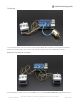
And Solder! Heat up your iron and solder in one header connection on the right. Once it is soldered, put down the solder and reheat the solder point with your iron while straightening the HAT so it isn't leaning down (For tips on soldering, be sure to check out our Guide to Excellent Soldering (https://adafru.it/aTk)). Solder one point on the opposite side of the connector Solder each of the connections for the top row © Adafruit Industries https://learn.adafruit.
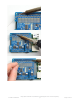
Flip the board around and solder all the connections for the other half of the 2x20 header © Adafruit Industries https://learn.adafruit.
© Adafruit Industries https://learn.adafruit.
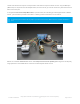
Check over your work so far, make sure each solder point is shiny, and isn't bridged or dull or cracked Now grab the 3.5mm-spaced terminal blocks. These will let you quickly connect up your motor and power supply using only a screw driver You will have 3 x 2-pin terminal blocks and 2 x 3-pin terminal blocks Slide each of the 3-pin terminal blocks into a 2-pin to create two 5-pin blocks Slide the terminal blocks along the edge of the HAT, so that the 'mouth' of each block is facing out.
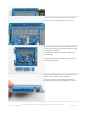
Flip over the board and solder in all of the terminal block pins © Adafruit Industries https://learn.adafruit.
Check over your work so far, make sure each solder point is shiny, and isn't bridged or dull or cracked You're done! You can now move onto the software side © Adafruit Industries https://learn.adafruit.
Powering Motors Motors need a lot of energy, especially cheap motors since they're less efficient. Voltage requirements: The first important thing to figure out what voltage the motor is going to use. If you're lucky your motor came with some sort of specifications. Some small hobby motors are only intended to run at 1.5V, but its just as common to have 6-12V motors. The motor controllers on this HAT are designed to run from 5V to 12V. MOST 1.
having a powerful enough supply! Even small DC motors can draw up to 3 Amps when they stall. Power it up Wire up your battery pack to the Power terminal block on the right side of the HAT. It is polarity protected but still its a good idea to check your wire polarity.
Installing Software We've written a handy CircuitPython library for the DC Motor and Stepper Pi Hat Kit called Adafruit CircuitPython MotorKit (https://adafru.it/DdU) that handles all the complicated setup for you. All you need to do is import the appropriate class from the library, and then all the features of that class are available for use. You can use this kit with a Raspberry Pi and Python thanks to Adafruit_Blinka, our CircuitPython-for-Python compatibility library (https://adafru.it/BSN).
Using DC Motors DC motors are used for all sort of robotic projects. The Motor HAT can drive up to 4 DC motors bi-directionally. That means they can be driven forwards and backwards. The speed can also be varied at 0.5% increments using the high-quality built in PWM. This means the speed is very smooth and won't vary! Note that the H-bridge chip is not meant for driving continuous loads over 1.2A or motors that peak over 3A, so this is for small motors.
Controlling DC Motors To demonstrate the usage, we'll initialise the library and use Python code to control a DC motor from the Python REPL. First you'll need to import and initialize the MotorKit class. from adafruit_motorkit import MotorKit kit = MotorKit() The four motor spots on the Pi hat are available as motor1 , motor2 , motor3 , and motor4 . In this example we'll use motor1 . Now to move a motor you can set the throttle attribute.
"""Simple test for using adafruit_motorkit with a DC motor""" import time from adafruit_motorkit import MotorKit kit = MotorKit() kit.motor1.throttle = 1.0 time.sleep(0.5) kit.motor1.throttle = 0 © Adafruit Industries https://learn.adafruit.
Using Stepper Motors Stepper motors are great for (semi-)precise control, perfect for many robot and CNC projects. This HAT supports up to 2 stepper motors. The python library works identically for bi-polar and uni-polar motors. Running a stepper is a little more intricate than running a DC motor but its still very easy. Connecting Stepper Motors For unipolar motors: to connect up the stepper, first figure out which pins connected to which coil, and which pins are the center taps.
from adafruit_motorkit import MotorKit kit = MotorKit() Similar DC motors, stepper motors are available as stepper1 and stepper2 . stepper1 is made up of the M1 and M2 terminals, and stepper2 is made up of the M3 and M4 terminals. We'll use stepper1 in our example. The most basic function (and the default) is to do one single coil step. kit.stepper1.onestep() There are a number of optional features available for the onestep() function.
motor in place, as seen in the animated GIF above 2. Double Steps - this is also fairly simple, except instead of a single coil, it has two coils on at once. For example, instead of just coil #1 on, you would have coil #1 and #2 on at once. This uses more power (approx 2x) but is stronger than single stepping (by maybe 25%) 3. Interleaved Steps - this is a mix of Single and Double stepping, where we use single steps interleaved with double.
"""Simple test for using adafruit_motorkit with a stepper motor""" from adafruit_motorkit import MotorKit kit = MotorKit() for i in range(100): kit.stepper1.onestep() © Adafruit Industries https://learn.adafruit.
Python Docs Python Docs (https://adafru.it/DeE) © Adafruit Industries https://learn.adafruit.
Stacking HATs One of the cool things about this HAT design is that it is possible to stack them. Every HAT you stack can control another 2 steppers or 4 DC motors (or a mix of the two) You can stack up to 32 HAT for a total of 64 steppers or 128 DC motors! Most people will probably just stack two or maybe three but hey, you never know.
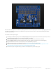
Board 0: Address = 0x60 Offset = binary 0000 (no jumpers required) Board 1: Address = 0x61 Offset = binary 0001 (bridge A0) Board 2: Address = 0x62 Offset = binary 0010 (bridge A1, the one above A0) Board 3: Address = 0x63 Offset = binary 0011 (bridge A0 & A1, two bottom jumpers) Board 4: Address = 0x64 Offset = binary 0100 (bridge A2, middle jumper) etc. Note that address 0x70 is the "all call" address for the controller chip on the HAT.
Downloads Motor ideas and tutorials Wikipedia has tons of information (https://adafru.it/aOF) on steppers Jones on stepper motor types (https://adafru.it/aOH) Jason on reverse engineering the stepper wire pinouts (https://adafru.it/aOI) Files PCA9685 PWM driver (https://adafru.it/emJ) TB6612 Motor driver (https://adafru.it/emK) PCB files on GitHub (https://adafru.it/rEN) HAT Fritzing object in the Adafruit Fritzing Library (https://adafru.
Fabrication Print This is a 'HAT mechanical standard' compatible! © Adafruit Industries https://learn.adafruit.
Bonnet! © Adafruit Industries https://learn.adafruit.
© Adafruit Industries https://learn.adafruit.
© Adafruit Industries Last Updated: 2019-06-19 04:39:39 PM UTC Page 31 of 31