Adam Equipment ABK, AFK Scales (P.N.
Easy Reference: Model name of the scale: Serial number of the unit: Software revision number (Displayed when power is first turned on): Date of Purchase: Name of the supplier and place: © Adam Equipment Company 2011
CONTENTS 1.0 INTRODUCTION .................................................................................................................................. 3 2.0 SPECIFICATIONS................................................................................................................................ 4 3.0 INSTALLATION .................................................................................................................................... 6 3.1 UNPACKING ......................................
2|P a g e © Adam Equipment Company 2011
1.0 INTRODUCTION • The ABK/AFK scales provides an accurate, fast and versatile general purpose weighing scales with parts counting, percent weighing and check-weighing functions. • The ABK/AFK has LEDs to indicate when a weight is below the low limit, between the limits or above the high limit next to the display. These can work in conjunction with an audible alarm for check weighing as well as LCD showing LO, OK and HI.
2.0 SPECIFICATIONS Model # Maximum Capacity Readability Resolution Repeatability (Std Dev) Linearity + Eccentric Loading Pan size wxd Units of Measure Stabilization Time Operating Temperature Power Supply Calibration Calibration Mass Display Draft Shield (w x d x h) Balance Housing Overall Dimensions (w x d x h) Net Weight ABK 8 ABK 16a ABK 16 ABK 35a ABK 32 ABK 70a ABK 60 ABK 130a ABK 120 ABK 260a 8000g/16lb 16kg/35lb 32kg/70lb 60kg/130lb 120kg/260lb 0.2g/0.0005lb 0.5g/0.001lb 1g/0.
Model # Maximum Capacity Readability Resolution Repeatability (Std Dev) Linearity + Eccentric Loading Pan size wxd Units of Measure Stabilization Time Operating Temperature Power Supply Calibration Calibration Mass Display Draft Shield (w x d x h) Balance Housing Overall Dimensions (w x d x h) Net Weight AFK 75/165a AFK 150/330a AFK 300/660a AFK 600/1320a 75kg/165lb 150kg/330lb 300kg/660lb 600kg/1320lb 5g/0.01lb 10g/0.02lb 20g/0.05lb 50g/0.1lb 1:15000 1:15000 1:15000 1:12000 5g/0.
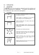
3.0 INSTALLATION 3.1 UNPACKING The ABK/AFK scales have already been adjusted to work with a platform and have been configured for this application. The platform and indicator have been calibrated as a pair and must be used together . 3.2 LOCATING • The scales should not be placed in a location that will reduce the accuracy. • Avoid extremes of temperature. Do not place in direct sunlight or near air conditioning vents. • Avoid unsuitable tables. The table or floor must be rigid and not vibrate.
3.3 SETTING UP THE SCALES • The pillar is attached to the base using a bracket that must be attached to the base frame first using the 4 bolts supplied. The pillar is secured to the bracket using 2 sets of screws. The cable from the base to the indicator module is run through the tube and taken out through the support at the top. Excess cable can be stored within the tube. • The ABK/AFK Series comes with a stainless steel platform packed separately. Place the platform in the base.
4.0 KEY DESCRIPTIONS [>Z/T<] If near zero, Sets the zero point for all subsequent weighing. The display shows zero. Tares the scale. Stores the weight currently on the scale as tare value, subtracts the tare value from the gross weight and shows the results A secondary function, is of “Enter” key used when setting up the value for the Parameters. [Pcs/ ] Selects parts counting. Used to set the sample quantities while parts counting.
[Func/C] Selects the Functions of the scale. If the scale is weighing, it will select parts counting. If it is not in weighing mode, it will return the user to weighing. A secondary function (C) is to act as a clear key when setting values for Parameters. [Print/M+/Esc] Sends the results to a PC or a Printer using the RS232 interface. It also adds the value to the accumulation memory if the accumulation function is not automatic.
5.0 DISPLAYS The LCD display will show a value and a unit to the right of the digits. In addition the LED’s above the display will show when a weight is below or above check-weighing limits. Other symbols will show when a weight has been tared (NET) the scale is at zero and stable, if a value has been stored in memory or when the animal weighing function has been enabled. A battery symbols will show the state of charge of the internal battery.
6.0 OPERATION 6.1 ZEROING THE DISPLAY • You can press the [Z/T] key at any time to set the zero point. This will usually be necessary when the platform is empty. When the zero point is obtained the display will show an indicator for zero. • The scale has an automatic re-zeroing function to account for minor drifting or accumulation of material on the platform. However you may need to press the [Z/T] key to rezero the scale if small amounts of weight are shown when the platform is empty. 6.
• Press the [Z/T] key to tare the scale. The weight that was displayed is stored as the tare value and that value is subtracted from the display, leaving zero on the display. The “NET” indicator will be ON. As a product is added only the net weight of the product will be shown. The scale could be tared a second time if another type of product was to be added to the first one. Again only the weight that is added after taring will be displayed. • When the container is removed a negative value will be shown.
6.4 PARTS COUNTING If parts counting is enabled, See section 7.4, it is possible to count parts using a sample of the parts to determine average piece weight. • Before starting, tare the weight of any container that may be used, leaving the empty container on the scale. Place a known number of samples in the container, if used. The number should match the options for parts counting, i.e., 10, 20, 50, 100 or 200 pieces.
• Press the [Pcs/ ] key to return to normal weighing. Press the [Pcs/ ] key again to start counting a different sample. 6.5 CHECK-WEIGHING Check-weighing is a procedure to cause lamps to come on (and if enabled, an alarm to sound) when the weight on the scale meets or exceeds values stored in memory. The memory holds the last values for a high and a low limit when the power is turned off. The user can set either one limit or both as described below. See Section 7.1 for the procedure to set the limits.
BOTH LIMITS SET The display will show OK F3 bEP = bP InL . when the weight is The beeper will sound between the limits when the weight is between the limits, i.e. OK F3 bEP = bP OtL Beeper will sound if weight is outside the limits. LOW LIMIT SET The display will show LOW HIGH LIMIT is set to when the weight is less zero than the Low Limit. Above the Low Limit the display will show OK, F3 bEP = bP InL . The beeper will be off when the weight is less than the Low Limit.
NOTE: Weight must be more than 20 scale divisions for check weighing to operate. Below 20 scale divisions the LED’s will not light and the beeper will not be on. The Check-weighing function can be set up during Weighing or Parts Counting by entering values as Low or/and High Limits keyed in by the user. The limits are displayed in kg (or Lb) or pcs respectively.
6.6 ACCUMULATED TOTAL • The scale can be set to accumulate manually by pressing the [Print/M+/Esc] key or automatically when a weight is removed from the scale. See the Section 7.3 for details of setting the Parameter “C3 PRM” and “C4 Aon”. The accumulation function is available when weighing or when counting parts. However the memory is cleared if the weighing units or functions are changed.
6.7 PERCENT WEIGHING The scale can be set to perform percent weighing. See Section 7.2. The scale will use a mass on the platform as the 100% reference weight. If the platform is empty (or the scale is tared) then the user can input a reference weight using the keypad. • Press [Func/C]. The first option is “FunC 1”, press the [Func/C] key again display “FunC 2”. • Press the [Z/T] key. “P1 PCt” will be displayed. • Press [Z/T] again to enter percent weighing.
comparison to the capacity of the system. A smaller weight will show only “100%” while a larger weight might show “100.00%”. • If the scale was showing zero weight when entering this function, then the user must manually enter the weight to be set as 100% as described below. • Press the [Z/T] key. “P1 PCt” will be displayed. • Press [Z/T] again to enter percent weighing. The scale will now accept a value the user enters as the reference weight.
6.8 ANIMAL (DYNAMIC) WEIGHING The scale can be set to animal (dynamic) weighing for weighing any items that are unstable or may move. See Section 7.4. The scale will use a special filter to minimise the effects of any movement while the moving animal or unstable samples are on the scale. • Press [Func/C]. The first option is “FunC 1”, press the [Func/C] key again to display “Func 2”. • Press the [Z/T] key. “F2 PCt” will be displayed.
6.8.1ANIMAL WEIGHING PROCEDURE • With the platform empty the display will show zero weight. Place containers or blankets onto the platform and press the [Z/T] key to zero the display. The scale may go into the animal (dynamic) weighing procedure when the items are placed on the scale but will return to showing zero when the [Z/T] key is pressed. • Place the animal or sample to be weighed on the platform. • The display will show the Animal/Dynamic weighing symbol until a stable weight is determined.
7.0 USER PARAMETERS Pressing the [Func/C] key during normal operation allows the user to access the parameters for customizing the scale. The parameters are split into 4 groups1. Check weighing parameters, 2. Percent and Animal Weighing Functions 3. RS-232 parameters and 4. Scale parameters • When [Func/C] is pressed, display will first show “FunC 1” for Check weighing parameters. • Press either the [Func/C] key or the [Pcs/ ] to advance through the groups “FunC 1”, “FunC 2” , “FunC 3” and “FunC 4”.
Parameter Description F1 Lo Set Low limit. F2 Hi Set High limit. Use the [Unit/] key 0000000 and [Pcs/ ] key to set the values of the high limit. When set press the [Z/T] key to store the value and go to F3 bEP F3 bEP This parameter sets the Beeper to off or on. If set to on, the beeper can further be set to sound when the weighing result is within or outside the check-weighing limits.
[Print/M+/Esc] again, the scale will exit the User Parameter section and return to weighing. Parameter Description P1 PCt This parameter allows the None user to enter the Percent weighing Function. See Section 6.7. P2 AnL Enter the Animal Weighing Set the filter value. mode of operation, See section 6.8 7.3 Options Default setting Enabled always Enabled Always RS-232 PARAMETERS • Press [Z/T] to enter a parameter.
C5 Ln the Accumulation Select Language C6 UId Set User ID C7 Sid Set Scale ID AC oFF EnGLi (English) EnGLi FrEnCH (French) GErmAn (German) SPAn (Spanish) To be entered 000000 manually To be entered 000000 manually Scale will perform the following, depending on the Accumulation and Print Settings: ACCUMULATION AC on AC Off SETTINGS PRINT SETTINGS Accumulate automatically AUto mAn Cont Not available approved scales 7.
This group of parameters is used to control the operation of the scale. Parameter Description S1 Un S2 bL S3 AoF S4 dt Options Default setting Kg Enable or disable weighing units, will not allow to disable all units, at least one has to be enabled.
8.0 BATTERY OPERATION • The scales can be operated from the battery if desired. The battery life can be up to 70 hours depending on the load cells used and how the backlight is used. • When the battery needs charging a symbol on the display will show less bars in the battery symbol. The battery should be charged when only the battery outline is on. Once the bars have been turned off the scale will still operate for a short time after which it will automatically switch off to protect the battery.
9.0 RS-232 INTERFACE The ABK/AFK indicator is supplied with bi-directional RS-232 interface as standard. The scale when connected to a printer or computer outputs the weight with the selected weighing unit through the RS-232 interface.
Data Format-Normal Output: Date Time Scale ID User ID Net Wt 12/09/2006 14:56:27 123456 234567 1.234 Kg If ID is zero, it is left blank Net Wt. (or Gross Wt.) Only weight value along with the weighing unit is printed. If Percent weighing is used then % is shown in place of weighing units. Data Format-Parts Counting Output: Weight, Unit weight and number of parts are printed.
Data Format- Memory Recall Output: Date 12/09/2006 Time 14:56:27 Scale ID 123456 User ID 234567 ------------------ TOTAL No. 5 Wt. 1.234 Kg PCS 10 pcs ------------------ Data Format- Continuous Output- Normal weighing: ST,GROSS US,NET 1.234 Kg 0.000 Kg ST or US for STable or UnStable, NET or GROSS for Net Weight or Gross wt. and the weighing unit, kg, lb etc.
Description Net weight ENGLISH FRENCH GERMAN SPANISH Net Wt. Pds Net Net-Gew Pso Net Weight per unit counted Unit Wt. Pds unit Gew/Einh Pso/Unid Number of items counted Pcs Pcs Stck. Piezas Nb. Anzhl Num. Total Gesamt Total Date Date Datum Fecha Time Heure Zeit Hora Scale ID Bal ID Waagen ID Bal ID User ID Util ID Nutzer ID Usuario ID Number of weighing added No. to subtotals Total weight and count printed Total Print date Print time Scale ID number User ID Number 9.
10.0 RELAY INTERFACE The indicator is supplied with drivers to control external relays. The drivers could be used to control a number of different relays depending upon the users need. The relay drivers are isolated outputs requiring the use of an external power supply for the relays. Also see section 3.4.3. Contact Adam Equipment or your supplier for a relay interface that is compatible with the relay drivers, however other interfaces can be used as long as the following conditions apply.
Connections to the drivers: Connections are made to the PCB, Connector P1. The connector is a spring activated type, simply press on the top of the connector and insert the wire. Do not exceed the safe limits of voltage or current of 24VDC or 15ma per output. Depending upon the application it may be necessary to use a small relay to drive larger relays, or to provide additional protection to prevent electromagnetic interference (diodes as shown above) to this or other machinery.
11.0 CALIBRATION The scale can be calibrated using the following procedure. To enter this procedure it is necessary to use Func 4 accessible using the [Func/C] key as described in section 7.4 or using the password access as described in section 12. The ABK/AFK scales calibrate using either metric or pound weights, depending on the weighing unit in use before calibration. The display will show either "kg" or "lb" to identify the weights expected.
12.0 SERVICE SECTION The scales will allow entry to the parameters if the [Tare] key is pressed during the power on cycle. The passwords work as above. In this case the display will show the passcode request screen, “ P - - - - “ . To continue enter a passcode as described below. Entering passcode 0000 will allow calibration as shown in section 11. Entering 1000 will allow access to a limited set of parameters described in section 12.1.
The parameters available are: “F4 Int” Initial Zero Range “F5 rEZ” Re-Zero range “F6 SCS” Successive Tare Enable “F7 Cnt” Display the A/D counts “F8 Zem” Zero Mode “F9 Lvd” Low voltage detection “FA AZn” Auto Zero Range “Fb FPS” User Function Password The description of the parameters is shown in section 12.3 12.
12.3 PARAMETER DETAILS 12.3.1 F1 -CALIBRATION To enter the calibration parameter, press the [Z/T] key when “F1” is displayed. The scale will be calibrated using 2 masses of approximately 1/3Maximum and Maximum. If the scale has been calibrated once the values will be stored. If this is the first time the scale is calibrated the user must enter the values for the calibration masses. NOTE: It is necessary to set the decimal point location and the capacity before calibration is possible.
12.3.3 F3 – CAPACITY/ WEIGHING UNIT/INCREMENT To enter this parameter, press the [Z/T] key when “F3 CAP” is shown. The display will show the current capacity and default weighing unit. Enter the numeric values using the [Unit/] and [Pcs/ ] keys. The scale will check the number of division’s n = maximum/increment is less than 30,000 divisions. (3000 divisions for EC approved versions).
12.3.4 F4 –INITIAL ZERO RANGE To enter this parameter, press the [Z/T] key when “F4 int” is shown. The display will show the current initial zero range. Press the [Pcs/ ] key to change the value and press [Z/T] to accept the value. Press [Print/M+/esc] to return to weighing. 12.3.5 F5 -RE-ZERO RANGE To enter this parameter, press the [Z/T] key when “F5 rEZ” is shown. The display will show the current re-zero range. Press the [Pcs/ ] key to change the value. Press [Z/T] to accept the value.
12.3.9 F9 –LOW VOLTAGE DETECTION This parameter allows detection of low voltage when the battery wears down. To enter this parameter, press the [Z/T] key when “F9 LVd” is shown. The display will show if the LVD Mode is set to on or oFF. Press the [Pcs/ ] key to change the value. Press [Z/T] to accept the displayed value. Press [Print/M+/Esc] to return to weighing. 12.3.10 FA –AZn Auto Zero Range This parameter sets the auto zero range from 0 (Off) to 4d.
13.0 ERROR CODES ERROR DESCRIPTION CODES - -oL - - Over-range SUGGESTIONS Remove weight from the scale. If the problem persists contact your dealer or Adam Equipment for assistance. Err 1 Time Error Setting Enter time using correct format and reasonable values. Format: hh:mm:ss Err 2 Date Error Setting Enter date using correct format and reasonable values.
14.0 REPLACEMENT PARTS AND ACCESSORIES If you need to order any spare parts and accessories, contact your supplier or Adam Equipment. A partial list of such items is as follows• • 15.0 • Power Supply Module Replacement Battery Printer, etc. SERVICE INFORMATION This manual covers the details of operation. If you have a problem with the scale that is not directly addressed by this manual then contact your supplier for assistance.
16.0 WARRANTY STATEMENT Adam Equipment offers Limited Warranty (Parts and Labour) for the components failed due to defects in materials or workmanship. Warranty starts from the date of delivery. During the warranty period, should any repairs be necessary, the purchaser must inform its supplier or Adam Equipment Company. The company or its authorised Technician reserves the right to repair or replace the components at any of its workshops depending on the severity of the problems.
45 | P a g e © Adam Equipment Company 2011
Manufacturer’s Declaration of Conformity This product has been manufactured in accordance with the harmonized European standards, following the provisions of the below stated directives: Electro Magnetic Compatibility Directive 2004/108/EC Low Voltage Directive 2006/95/EC Adam Equipment Co. Ltd. Bond Avenue, Denbigh East Milton Keynes, MK1 1SW United Kingdom FCC COMPLIANCE This equipment has been tested and found to comply with the limits for a Class A digital device, pursuant to Part 15 of the FCC Rules.
ADAM EQUIPMENT is an ISO 9001:2008 certified global company with more than 35 years experience in the production and sale of electronic weighing equipment. For a complete listing of all Adam scales and balances visit our website at: www.adamequipment.com © Copyright by Adam Equipment Co. Ltd. All rights reserved. No part of this publication may be reprinted or translated in any form or by any means without the prior permission of Adam Equipment.