Adam Equipment CPWplus plus RANGE OF SCALES (P.N. 9428, Rev.
© Adam Equipment Company 2008
CONTENTS 1.0 INTRODUCTION.............................................................................................. 3 2.0 SPECIFICATIONS ........................................................................................... 4 3.0 INSTALLATION................................................................................................ 7 3.1 UNPACKING ................................................................................................ 7 3.2 LOCATING ....................................
© Adam Equipment Company 2008 2
1.0 INTRODUCTION The CPWplus range of Platform Scales has a stainless steel top pan on a steel frame and an indicator with a large backlit LCD. The waterresistant keyboard has 4 easy to use function keys: [On/Off], [Print/Hold], [Unit], and [Tare/Zero]. All scales are supplied with the Power Supply module.
2 g / 0.005 lb 4 g / 0.01 lb Repeatability Linearity 10 g / 0.02 lb 5g/ 0.01 lb 15kg x 5g 33 lb x 0.01 lb 520 oz x 0.2 oz 32 lb:16oz x 1 oz CPWplus plus 15* CPWplus plus 15P* 20 g / 0.04 lb 10 g / 0.02 lb 35 kg x 10 g 75 lb x 0.02 lb 1200 oz x 0.5 oz 74 lb:16 oz x 1 oz CPWplus plus 35 CPWplus plus 35P* CPWplus plus 35W CPWplus plus 35M CPWplus plus 35L 40 g / 0.1 lb 20 g / 0.05 lb 75 kg x 20 g 165 lb x 0.
© Adam Equipment Company 2008 Applications Scale housing Keypad Display Series Platform size 300 x 300 mm / 11.8” x 11.8” 500 x 500 mm / 19.7” x 19.7” 900 x 600 mm / 35.4” x 23.6” Power Option Power supply module supplied 6 x AA size batteries Internal rechargeable battery (~ 60 hrs) Net weight 4 kg / 8.8 lb 5.25 kg / 11.6 lb 10.5 kg / 23.1 lb 8.5 kg / 18.7 lb 17 kg / 37.
© Adam Equipment Company 2008 6
3.0 INSTALLATION 3.
3.2 LOCATING • The scales should not be placed in a location that will reduce the accuracy. • Avoid extremes of temperature. Do not place the scale in direct sunlight or near air conditioning vents. • Avoid unsuitable surfaces. The table or floor should be rigid and free from vibration. • Avoid unstable power sources. Do not use the scale near large users of electricity such as welding equipment or large motors. • Do not place the scale near vibrating machinery.
3.3 SETTING UP 3.3.1 SETTING UP THE STANDARD CPWplus plus SERIES 1 Remove the parts from the packing carefully. Place the base on a rigid surface. Place the Stainless Steel pan on the base, if it not already assembled. 2 The indicator is separately packed and comes attached to a bracket with the help of two thumb screws. Bracket Thumb Screw To adjust the angle of the indicator, use the two thumb screws on the side of the bracket that connects the indicator.
3.3.2 SETTING UP THE CPWplus plus P SERIES (FOR USA ONLY) The CPWplus scale can be ordered with the Pillar or the Pillar can be added at a later stage to convert the scale into the Pillar version (Currently the Pillar version is available in USA only). 1 The Pillar comes separately packed. Remove it from the packaging. Indicator 2 Connect the cable attached to the Pillar to the connector inside the plastic socket situated at the base. Tighten the ferrule to secure the cable.
3.3.3 SETTING UP THE CPWplus plus M & CPWplus plus L SERIES 1 2 Remove the parts from the packing carefully. Place the base on a rigid floor. Place the Stainless Steel pan on the base, if it not already assembled. Level the base using the four adjustable feet. Adjustable feet For CPWplus L, place the optional rubber mat on the pan for animal weighing. 4 3 The indicator is separately packed and comes attached to a bracket with the help of two thumb screws.
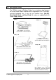
3.3.4 SETTING UP THE CPWpplus W SERIES 2 1 There are two wheel attachments to be fixed at the rear of the base. Fasten them to the bottom of the base by using the two hex-headed screws for each wheel attachment. Wheel attachment Place the base on a rigid floor and level it using the 4 adjustable feet. Install the handle in the vertical position by inserting the ends into the circular sockets attached to the wheels. Secure the handle by using two M6 screws at each end.
4.0 KEYPAD [On / Off] Turns the scale on or off only [Print/Hold] Sends data via RS-232 and combines with Hold functions, if enabled Selects kilograms, pounds, ounces or pounds-ounces [Unit] [Tare/Zero] Sets the display to true zero or net zero by storing the current weight in the tare memory 5.0 DISPLAY 6.
7.0 BATTERY • CPWplus standard and CPWplus-P (for USA only) can be operated from 6x AA batteries, if desired. • CPWplus-W, CPWplus-M and CPWplus-L scales have an internal rechargeable battery. When the battery needs charging a symbol on the display will turn on. The battery should be charged when the symbol is on. • To charge the battery, connect the power supply module to the rear of the indicator and apply power. The scale need not be turned on.
• The scale will turn off automatically to conserve battery life if the automatic turn off parameter is set (see section 13.1.1). To turn off the scale press the [On/Off] key. • A battery symbol will be on when the internal battery needs to be re-charged. Connect the power supply module to the rear of the indicator and switch on the mains. 10.2 ZEROING • The ZERO and TARE function is combined into one key [Tare/Zero]. • You can press the [Tare/Zero] key at any time to set a new zero point.
subtracted from the display, leaving zero on the display. The indicator “Net” will be on. • As a product is added to the container, only the weight of the product will be shown. The scale could be tared a second time if another type of product was to be added to the first one. Again only the weight of the product that is added after taring will be displayed. • When the container is removed a negative value will be shown.
11.0 RS-232 INTERFACE The CPWplus scales come with a bi-directional RS-232 interface. U Interface parameters are: U Connection details are: Connector: 9 pin D-subminiature socket Pin 3 Output Pin 2 Input Pin 5 Signal Ground RS-232 output of weighing data ASCII code Selectable Baud Selectable data bits Selectable Parity U Normal OutputU: (See section 13.1.7) add: A G/W: + 2.00 kg add: A N/W: + 1.
12.0 CALIBRATION • Occasionally the scale should be verified whether it is weighing correctly by measuring to a known mass. • Zero the scale. Place the mass on the centre of the platform and note the reading. Calibrate the scale, if necessary. PROCEDURE • While in the normal weighing mode, press and hold the [Tare/Zero] key for 4 seconds. • The display will show “CAL” along with the last selected unit. The unit can be changed by using the [Unit] key to calibrate in kg or lb. • Press the [Print/Hold] key.
• Place the correct calibration mass as selected by the user at the centre of the pan. • Press the [Unit]. The display will return to weighing mode. Note: If the mass loaded is more than ±20% of the factory calibration reference then an error message “CALEr” will be displayed and the scale will return to weighing without calibration being saved. Repeat the process correctly. • Remove the weight. • Verify the scale is calibrated correctly. Repeat the process, if necessary. 13.0 PARAMETER SETTING 13.
13.1.1 AUTO POWER OFF • The first parameter is to set the auto power off function. The display will show “Pr oFF” (DEFAULT SET). • Press [Tare/Zero] to toggle between “Pr on” and “Pr oFF”. Enables the Auto Power Off function. The power will be turned off after 2 minutes if a key has not been pressed for 2 minutes and the scale is at zero. If there is any weight on the scale or a key is pressed, the scale will continue to work. Disables the Auto Power Off function. The scale will not automatically turn off.
13.1.3 ENABLING OF UNITS • The third parameter is to enable or disable the weighing units so that the user can select the enabled units during the weighing operation. Display will show “on kg” (DEFAULT SET) • Use [Tare/Zero] to toggle between “on” and “oFF”. Enables the unit Disables the unit • Press the [Unit] key to confirm the selection and move to the next unit which is “lb”. • After all units are set, press the [Unit] key to move to the next parameter. 13.1.
13.1.5 13.1.6 SELECTION OF BAUD RATE • The fifth parameter is to select the baud rate per second which is the speed of sending data to RS-232 interface. Display will show “b 9600” (DEFAULT SET) • Use the [Tare/Zero] key to scroll through the options. • There are three options- • Press the [Unit] key to confirm the selection and move to the next parameter. SELECTION OF BIT RATE AND PARITY • The sixth parameter is to select the bit rate and parity used for sending data to RS-232 interface.
13.1.7 SELECTION OF TRANSMISSION MODE • The seventh parameter is to select the transmission mode. Display will show “trn 1” (DEFAULT SET). See the HOLD AND PRINTING TABLE in section 13.1.9. No data output Continuous data output Normal output when the [Print/Hold] key is pressed • Use the [Tare/Zero] key to scroll through the options. • Press the [Unit] key to confirm the selection and move to the next parameter. 13.1.8 SELECTION OF HOLD FUNCTION • The eighth parameter is to set the Hold function.
• If “Hod 1” is selected, pressing the [Unit] key will take you back to the first parameter on Auto Power Off. • If you want to return to weighing, press the [Print/Hold] key. 13.1.9 SETTING OF HOLD TIME LIMIT • This parameter is to set the time limit by which the display is held after the hold function is used. It is applicable if the hold function is set to “Hod 2” or “Hod 3”. • Use the [Tare/Zero] key to scroll through the options.
HOLD AND PRINTING TABLE trn 1 trn 2 trn 3 Hod 1 RS-232 is off. Hold is off. [Print/hold] key has no function. Prints continuously. Hold is off. [Print/hold] key has no function. RS-232 prints when [Print/Hold] is pressed. Hold function is disabled. Hod 2 RS-232 is off. Hold occurs automatically when the weight is stable. Hold is released if [Print/Hold] is pressed or time expires as per Hti setting. Print continuously. Hold occurs automatically when the weight is stable.
13.2.1 FILTER This parameter is for setting the speed of the display filter. For poor environments the filter should be set at its slowest to minimise external influences on the scale. For weighing small samples or gradual filling, the filter should be set at a faster setting. • Press [Tare/Zero] to scroll through the options. The display will show “Fi 1” to “Fi 3”. If it is set to “F1 1” then the display is at its slowest setting and at “F1 3” the display is in its fastest setting.
• Press [Tare/Zero] to scroll through the settings. The display will show “StA 1” to “StA 8”. If it is set to “StA 8” then the stability is at its fastest and “StA 1” the slowest. • Press [Unit] to confirm the selection and move to the next parameter. 13.2.4 STABILIZATION TRACKING This parameter is for setting the size of the tracking range to indicate the stability. This is used to stable the scale once a weighing result is achieved. • Press [Tare/Zero] to scroll through the settings.
14.0 ERROR MESSAGES During the initial power-on testing or during the operation the scale may show an error message. The error messages are described below. ERROR CODE DESCRIPTION POSSIBLE CAUSES A continuous beep is heard. Weight on the pan exceeds the capacity of the scale. Remove the weight from the pan. If the selected mass is Incorrect calibration mass. less than 10% or more Repeat the process correctly.
16.0 SERVICE INFORMATION This manual covers the details of operation. If you have a problem with the scale that is not directly addressed by this manual then contact your supplier for assistance. In order to provide further assistance, the supplier will need the following information which should be kept ready: A. Details of your company -Name of your company: -Contact person’s name: -Contact telephone, e-mail, fax or any other methods: B.
17.0 WARRANTY INFORMATION Adam Equipment offers Limited Warranty (Parts and Labour) for the components failed due to defects in materials or workmanship. Warranty starts from the date of delivery. During the warranty period, should any repairs be necessary, the purchaser must inform its supplier or Adam Equipment Company. The company or its authorised Technician reserves the right to repair or replace the components at any of its workshops depending on the severity of the problems.
18.
© Adam Equipment Company 2008
Manufacturer’s Declaration of Conformity This product has been manufactured in accordance with the harmonised European standards, following the provisions of the below stated directives: Electro Magnetic Compatibility Directive 89/336/EEC Low Voltage Directive 73/23/EEC Adam Equipment Co. Ltd. Bond Avenue, Denbigh East Milton Keynes, MK1 1SW United Kingdom FCC COMPLIANCE This equipment has been tested and found to comply with the limits for a Class A digital device, pursuant to Part 15 of the FCC Rules.
ADAM EQUIPMENT is an ISO 9001:2000 certified global company with more than 35 years experience in the production and sale of electronic weighing equipment. Adam products are predominantly designed for the Laboratory, Educational, Medical, retail and Industrial Segments.