Adam Equipment GFC Series (P.N. 3056610559, Revision A1, February 2009) Software Rev 2.
Easy Reference: Model name of the indicator/scale: Serial number of the unit: Software revision number (Displayed when power is first turned on): Date of Purchase: Name of the supplier and place: © Adam Equipment Company 2010
1.0 CONTENTS 1.0 CONTENTS ..........................................................................................1 2.0 INTRODUCTION...................................................................................3 3.0 INSTALLATION ....................................................................................5 3.1 UNPACKING......................................................................................5 3.2 LOCATING.............................................................................
Page 2 © Adam Equipment Company 2010
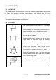
2.0 INTRODUCTION • The GFC series provides accurate, fast and versatile parts counting scales. • There are 2 types of scales within the GFC series: GFC scales are kilogram/gram scales and the GFC-a scales are changeable from pounds to kilograms if the user requires it. The scales have the same functions except that GFC-a scales have the ability to toggle between the two weighing units.
2.0 SPECIFICATIONS GFC 75 GFC150 GFC 300 GFC 165a GFC 330a GFC 660a Maximum Capacity 75kg 150kg 300kg 75kg / 165lb 150kg / 330lb 300kg / 660lb Readability 5g 10g 20g 5g / 0.01lb 10g / 0.02lb 20g / 0.05lb 5g 10g 20g 5g / 0.01lb 10g / 0.02lb 20g / 0.05lb 10g 20g 40g 10g / 0.02lb 20g / 0.04lb 40g / 0.1lb 15g 30g 60g / 15g / 0.03lb 30g / 0.06lb 60g / 0.
3.0 INSTALLATION 3.1 UNPACKING This indicator must be connected to a load cell platform and calibrated as necessary to match the platform and user requirements. See Section 15.0 for set-up information. The user’s application and the technical specifications of the platform or load cell will determine the necessary configuration. 3.2 LOCATING • The scales should not be placed in a location that will reduce the accuracy. • Avoid extremes of temperature.
3.3 SETTING UP THE SCALES • The pillar is attached to the base using a bracket that must be attached to the base frame first using the 4 bolts supplied. The pillar is secured to the bracket using 2 sets of screws. The cable from the base to the indicator module is run through the tube and taken out through the plastic support at the top. Excess cable can be stored within the tube. • The GFC Series comes with a stainless steel platform packed separately. Place the platform in the base.
4.0 KEY DESCRIPTIONS Keys [0-9, .] Functions Numeric entry keys, used to manually enter a value for tare weights, unit weight, and sample size. [CE] Used to clear the unit weight or an erroneous entry. [M+] Add the current count to the accumulator. Up to 99 values or full capacity of the weight display can be added. Also prints the displayed values when Auto print is switched off. [MR] To recall the accumulated memory. [Pst] To set the upper limit for the number of items counted.
5.0 DISPLAYS The scales have three sections. These are “Weight”, “Unit Weight” and “Count”. The LCD design is: WEIGHT UNIT WEIGHT COUNT 5.1 WEIGHT DISPLAY It has 6-digit display to indicate the weight on the scale.
5.2 UNIT WEIGHT DISPLAY This display will show the unit weight of a sample. This value is either input by the user or computed by the scale. The unit of measurement is grams if grams if kilograms is selected for the weighing unit, or pounds if pounds is selected. 5.3 COUNT DISPLAY This display will show the number of items on the scale or the value of the accumulated count. See the next section on OPERATION. 5.
6.0 OPERATION NOTE: GFC-a Scales only SETTING THE WEIGHING UNIT, lb or kg The scale will turn on displaying the last weighing unit selected, either kilograms or pounds. To change the weighing unit press the [U. Wt./Units] key when the “Unit Weight” display shows zero. If necessary press the [CE] key to clear the unit weight before changing. 6.1 ZEROING THE DISPLAY • You can press the [Zero] key at any time to set the zero point from which all other weighing and counting is measured.
6.2.1 Preset Tare • The user can enter a preset tare value if the display is at zero or gross weight. Enter the value for preset tare using the keypad, then press the [Tare] key to set the preset zero value. • If the display was at zero the weight will show a negative value equal to the preset tare value entered and the “Net” indicator will be on. 6.3 PARTS COUNTING 6.3.1 Setting Unit Weight In order to do parts counting it is necessary to know the average weight of the items to be counted.
B. Entering a known Unit Weight • If the unit weight is already known then it is possible to enter that value using the keypad. • Enter the value of the unit weight in grams, using the numeric keys followed by pressing the [U. Wt./Units] key. The "Unit Weight" display will show the value as it was entered. • The sample is then added to the scale and the weight will be displayed as well as the quantity, based on the unit weight. 6.3.
6.3.4 Manually Accumulated Totals • The values (weight and count) shown on the display can be added to the values in the memory by pressing the [M+] key. The "Weight" display will show the total weight, the "Count" display will show the total accumulated count and the "Unit Weight" display shows the number of times, the items have been added to the memory for accumulation. The values will be displayed for 2 seconds before returning to normal.
7.0 USER PARAMETERS The parameters are set to customise the scale to suit the weighing applications. You need to enter a secure menu by entering a password when requested. • Press [Tare] once, during the initial counting of the display after the power is turned on. • The “Weight” display will show "PIn number. " requesting for the password • The default password is "0000" but other numbers can be set using the parameter menus. Press the [0] key four times. • Press the [Tare] key.
SETTING OF PIN • Display will show “F2” “Pin”. This parameter allows setting of a new password number. The default password is “0000”. • Press [Tare]. The “Weight” display will show "Pin 1". • Enter the new password number. The “Unit Weight” display will show dashes. Press [Tare]. • The “Weight” display will change to "Pin 2 ", Enter the password again and press [Tare]. • The display will show "donE" to show the new password has been accepted and will return to the menu.
8.0 CALIBRATION • The GFC scales are calibrated using metric weights and GFC-a scales are calibrated using metric or pound weights depending on the unit in use before calibration. See the Service parameters section for more information. • The scale will display a value of the weight to be used for calibration, this value is the last weight used for calibration. You can enter a different value, if desired. • For entering Calibration, see section 7.0 Parameters • When “F1” “CAL” is displayed, press [Tare].
9.0 RS-232 INTERFACE The GFC Series are supplied with a RS-232 bi-directional interface. The scale when connected to a printer or computer through the RS-232 interface, outputs the weight, unit weight and count.
Data Format-Normal Output: DATE TIME GROSS Wt Unit Wt. Pcs 12/09/2006 14:56 Net Wt. if net weight is displayed Kg or g for metric weights and lb for pounds. 1.234 Kg 123 g 10 pcs Includes 2 line feeds with carriage return at beginning and end of the form Data Format- Memory Recall Print: DATE 12/09/2006 TIME 14:56 -----------------TOTAL No. 5 Wt. 1.
Data Format- Continuous Print: ST,GS, U.W. PCS 0.9080 kg 0.90798 g/pcs 1000 pcs Includes 2 line feeds with carriage return between sets of data In other languages the format is the same but the text will be in the language selected. See Section 9.2 Description ENGLISH FRENCH GERMAN SPANISH Print gross Gross Wt weight Pds Brut Brut-Gew Pso Brut Net Wt. Pds Net Net-Gew Pso Net Weight per Unit Wt. unit counted Pds unit Gew/Einh Pso/Unid of Pcs Pcs Stck.
9.1 INPUT COMMANDS FORMAT The scale can be controlled with the following commands. The commands must be sent in upper case letters, i.e. “T” not “t”. Press the Enter key of the PC after each command. T Tares the scale to display the net weight. This is the same as pressing [Tare] key. Z Sets the zero point for all subsequent weighing. The display shows zero. Same as pressing the [Zero] key. P Prints the weight, unit weight and totals same as pressing the [Print] key.
9.2 RS-232 SETUP The RS-232 interface uses parameters set by the user for language, baud rate and date format. Press and hold the [Print] key for 4 seconds to access the parameters. Press [U. Wt./Units] to scroll through the options and [Tare] to confirm the change and then advance to the next parameter. When a parameter is entered by pressing [Tare], the displays will guide you through the parameter selected and the options available.
The scale will perform the following functions depending on the Accumulation and Print settings: ACCUMULATION FUNCTIONS PRINT FUNCTIONS Print Auto Print mAn Cont to PC AC Auto AC mAn AC oFF Accumulate and Print automatically ; Print automatically, print automatically [M+] key has no Accumulate and print function when [M+] is pressed Automatically Accumulate and print Print when [Print] key Accumulate but not when [M+] or [Print] is is pressed, [M+] key has no function print, Print only pressed whe
9.3 REAL TIME CLOCK SETUP The Real Time Clock (RTC) is used only for the RS-232 output. The Date and Time can be set as required. The scale will keep the clock running even when the power is off. Setting up the clock • Press and hold the [CE] key for 4 seconds, release when the date and time is displayed. The initial displays show the current date and time set. “ rtC “ “11,14,06” “16,41,35” • Press the [CE] key to change the date and time. The display will show the current time in the format, “H-m-S”.
9.4 AUTO SLEEP FUNCTION This function may be enabled or disabled by the user. If enabled, when the scale is not used for some time (as pre-set by the user under this function) it automatically switches off. To set this parameter• Press and hold the [Zero] key for 4 seconds, release when the display shows “SLEEP nodE”. • Press [U/Wt/Unit] key to scroll through the auto sleep values.
10.2 BACKLIGHT FOR LCD • The backlight of the LCD can be set to be“1”: ON at all the time, “2”: ON only when a weight is placed on the scale or “3”: Turned off. • To set the backlight press and hold [Pst] key for 4 seconds. • The weight display will show “EL xx” where xx is the current setting for the backlight. Press [U. Wt./Units] to scroll through the options. Sets the backlight to be on at all times.
11.0 ERROR CODES During the initial power-on testing or during operation, the scale may show an error message. The meaning of the error messages is described below. If an error message is shown, repeat the step that caused the message, turning the balance on, carry out the calibration or other functions. If the error message is still shown contact your dealer for further support. ERROR CODE DESCRIPTION POSSIBLE CAUSES Err 1 Time input error. Tried to set an illegal time, i.e.
12.0 SERVICE PARAMETERS 12.1 USING “0000” TO ENTER THE CALIBRATION PARAMETER • Press the [Tare] key during the display counting when turned on. The display will ask for a code number, “Pin “ on the Weight Display. • Enter the number 0000 when “Pin “ is displayed and then press [Tare]. If another PIN number has been previously stored enter that number instead. • The displays will show the first parameters, called “F1” “CAL”. • To select another parameter press the [U.Wt.
12.1.1 F1 -CALIBRATION To enter the calibration parameter, press the [Tare] key when “F1” “CAL” is displayed. The scale should be calibrated using a mass of approximately 2/3Maximum to Maximum. If the scale has been calibrated previously the value will be stored. Details of calibration are given is section 8.0 . 12.1.2 F2 –PIN • To enter this parameter, press the [Tare] key when “F2” “Pin” is shown. • The “Weight” display will show “Pin 1” • Enter the new password.
13.0 REPLACEMENT PARTS AND ACCESSORIES If you need to order any spare parts and accessories, contact your supplier or Adam Equipment.
P a g e 30 © Adam Equipment Company 2010
14.0 SERVICE INFORMATION This manual covers the details of operation. If you have a problem with the scale that is not directly addressed by this manual then contact your supplier for assistance. In order to provide further assistance, the supplier will need the following information which should be kept ready: A. Details of your company -Name of your company: -Contact person’s name: -Contact telephone, e-mail, fax or any other methods: B.
15.0 WARRANTY INFORMATION Adam Equipment offers Limited Warranty (Parts and Labour) for the components failed due to defects in materials or workmanship. Warranty starts from the date of delivery. During the warranty period, should any repairs be necessary, the purchaser must inform its supplier or Adam Equipment Company. The company or its authorised Technician reserves the right to repair or replace the components at any of its workshops depending on the severity of the problems.
Manufacturer’s Declaration of Conformity This product has been manufactured in accordance with the harmonised European standards, following the provisions of the below stated directives: Electro Magnetic Compatibility Directive 2004/108/EC Low Voltage Directive 2006/95/EC Adam Equipment Co. Ltd. Bond Avenue, Denbigh East Milton Keynes, MK1 1SW United Kingdom FCC COMPLIANCE This equipment has been tested and found to comply with the limits for a Class A digital device, pursuant to Part 15 of the FCC Rules.
ADAM EQUIPMENT is an ISO 9001:2000 certified global company with more than 35 years experience in the production and sale of electronic weighing equipment. Adam products are predominantly designed for the Laboratory, Educational, Medical, retail and Industrial Segments.