Adam Equipment CBDa SERIES (P.N. 6242, Revision A9, June 2007) Software revision: 1.4-1.
CONTENTS 1.0 INTRODUCTION ........................................................................................................... 2 2.0 TECHNICAL SPECIFICATIONS.................................................................................... 3 2.1 SPECIFICATIONS FOR THE LOCAL SCALE ........................................................... 3 2.2 SPECIFICATIONS FOR THE REMOTE SCALE........................................................ 3 2.3 COMMON SPECIFICATIONS.....................................
1.0 INTRODUCTION • The CBDa series offers a range of an accurate, fast and versatile counting scales that can use one additional external platform (Remote scale) for weighing or counting of heavier items. • These counting scales have the ability to store detailed information on the products that are used most (PLU). • The scale can be operated using either pounds only, kilograms only or can be switched between pounds and kilograms. • All have stainless steel weighing platform on a Steel base assembly.
2.0 TECHNICAL SPECIFICATIONS 2.1 SPECIFICATIONS FOR THE LOCAL SCALE Model # CBD 6a CBD 12a CBD 35a CBD 65a CBD 100a 6 lb / 3 kg 12 lb / 6 kg 35 lb / 15 kg 65 lb / 30 kg 100 lb / 45 kg Readability 0.0002 lb / 0.0001 kg 0.0005 lb / 0.0002 kg 0.001 lb / 0.0005 kg 0.002 lb / 0.001 kg 0.005 lb / 0.002 kg Tare Range -6 lb / -3 kg 0.0002 lb / 0.0001 kg -12 lb / -6 kg 0.0005 lb / 0.0002 kg -35 lb / -10 kg 0.001 lb / 0.0005 kg -65 lb / -30 kg 0.002 lb / 0.001 kg -100 lb / -45 kg 0.005 lb / 0.
2.3 COMMON SPECIFICATIONS Interface Bi-directional RS-232 Interface Stabilisation Time 2 Seconds Operating Temperature 32°F - 104°F / 0°C - 40°C Power supply 9 VDC 800 mA from external power supply Calibration Automatic external Display 3 x 6 digits LCD digital display Housing Indicator ABS Plastic, Stainless Steel platform Pan size 8.9” x 10.8” / 225 x 275 mm Overall dimensions 12.4” x 14” x 4.3” / 315 x 355 x 110 mm Net weight 9 lb / 4.
3.0 INSTALLATION 3.1 3.2 LOCATING THE SCALES • The scales should not be placed in a location that will reduce the accuracy. • Avoid extremes of temperature. Do not place in direct sunlight or near air conditioning vents. • Avoid unsuitable tables. The table or floor must be rigid and not vibrate. • Avoid unstable power sources. Do not use near large users of electricity such as welding equipment or large motors. • Do not place near vibrating machinery.
• Level the scale by adjusting the four feet. The scale should be adjusted such that the bubble in the spirit level is in the centre of the level and the scale is supported by all four feet. • Attach the power supply cable to the connector on the right side of the scale base. Plug in the power supply module. The power switch is located at the right side of the scale base.
REMOTE SCALE CONNECTION The cable for the load cell goes to a 9 pin D-subminiature plug connector with the following connections: Pin numbers Pins 1,2 Pins 4,5 Pin 7 Pin 8 Connection - Excitation (0 V) + Excitation (+5 V) + Signal - Signal (The sense wires connections of a six wire load cell are not used but can be connected to the respective Excitation pins). REMOTE SCALE SET UP The remote scale should set for a realistic resolution with respect to the input provided by the load cell/s.
4.0 KEY DESCRIPTIONS [0-9, •] These keys are used to manually enter a value for tare weights, unit weight and sample size. A secondary function is to enter alpha-numeric characters for PLU descriptions etc. [CE] Pressing this key clears the unit weight or an erroneous entry. It also clears the memory accumulation when the total is displayed. [M+] This key is used to add the current count to the accumulator. It also recalls the memory when pressed with no load on the scale.
[Local Rem] This key is used to select the local or remote scale. [Tare/Zero] This key has a combined Zero and Tare function. If the net weight is below ±2% of maximum then it acts as a Zero key. This sets the zero point for all subsequent weighing by setting the display to zero. It also tares the scale by storing the current weight in the memory as a tare value, subtracting the tare value from the total weight and displaying the results as a net weight. 5.
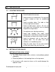
5.2 UNIT WEIGHT WINDOW • This display will show the unit weight of a sample. This value is either entered by the user manually or computed by the scale. The unit of measure is either gram on all scales with kilogram selected as weighing unit or in pounds. • When the scale has determined that there is insufficient number of samples to accurately determine the count, an arrow will be shown above "Smpl". • When the unit weight is not large enough to determine an accurate count, the arrow will show at "U.Wt".
6.0 OPERATION • The basic weighing functions are same for both the scales- local and remote. However the number of weighing divisions may be less on the remote scale dependant on the total capacity of the load cell/s used. • Each scale (local or remote) has the ability to count parts based on the current unit weight. This is best obtained by performing a sample on the local scale which may have the best sensitivity. Then the scale can be switched to the remote where large quantities can be counted.
6.1 ZEROING AND TARING THE DISPLAY The Tare and Zero function are combined into one key. When the gross weight is within ±2% of the zero, set at power on for either scale then a new zero is set. If the gross weight is greater than ±2% then the tare function is performed. ZEROING • You can press the [Tare/Zero] key at any time to set the zero point from which all other weighing and counting is measured. When the zero point is obtained the Weight display will show the indicator at “Zero”.
• When the container is removed a negative value will be shown. If the scale was tared just before removing the container this value is the gross weight of the container plus all products that were removed. The zero indicator will also be ON because the platform is back to the same condition as it was when the [Tare/Zero] key was last pressed. Second method of entering a tare value: • This method allows you to enter a value for the tare weight from the keypad.
6.2 MEMORY FUNCTIONS The [M+] key will add the results of a weighing into memory, regardless of whether the local or remote scale is being used for the weighing. 6.2.1 Manual accumulation • The values (weight and count) shown on the display can be added to the values in the accumulator by pressing the [M+] key.
6.3 PARTS COUNTING The basic function of parts counting is same for both the scales. In order to do parts counting it is necessary to know the average weight of the items to be counted. This can be done either by weighing a known number of the items and letting the scale determine the average unit weight or by manually inputting a known unit weight using the keypad.
6.3.2 Entering a known Unit Weight • If the unit weight is known it can be entered using the keypad. • Enter the value of the unit weight using the numeric keys followed by pressing [U. Wt.] within few seconds while the display is flashing. If no action is initiated within a few seconds, the "Unit Weight” display will revert to the previous value, otherwise it will show the new value that has been entered.
6.3.4 Count pre-set or check-weighing Check-weighing (or Count Pre-setting) is a procedure to cause an alarm to sound when the net weight (or the number of items) on the scale meets or exceeds a number stored in memory. The value to be stored is entered from the keyboard. SETTING OF PRESET LIMITS It is possible to set a high and low limit for either counting or weighing (using net weight). When the [Pst] key is pressed the user can select either counting or weighing and then set the lower and upper limit.
6.4 PLU (Product Look Up) Product Look-Up (PLU) numbers are used to store information about the commonly used items. The Tare Weight, Description of the product and Unit Weights for a particular item are recalled by entering the PLU number for ease of operation. The scale is capable of storing values for the Tare weight, Description and Unit Weight for a maximum of up to 100 PLU numbers. Tare Weight value is required for calculating the Net Weight where a container is used during weighing.
Please find below an example for setting up “PLU 27” with Description as “M4 Nut” and Unit weight of “0.015”. ACTIONS REMARKS Press [PLU] Weight “PLU ” DISPLAYS Unit weight Count “ - -“ “ “ Press [2], [7] “PLU ” “ 27” “ - Press [Pst] “PLU 27” “x x x x x x” “x x x ” Pressing the [CE] “PLU 27 ” “ key when the first character is flashing will clear all the descriptions. “ “ “ “ Continue to enter characters until description is complete.
6.4.2 ENTERING DESCRIPTION MANUALLY The description can be up to 12 characters long and can be a mix of numbers, symbols or letters. During the procedure to set the description the numeric keypad will work in a similar way to a mobile telephone. Pressing a number briefly will show the number and holding it down will scroll through all the characters.
6.4.3 RECALLING PLU’S MANUALLY • To recall the PLU values the user should first select either local or remote scale as the tare value stored will be specific to the scale selected. • Then press the [PLU] key, enter the PLU number (00 – 99) then press the [PLU] key again to recall the data. • The display will show the results of the recall for 1 second then return to weighing with the data in place.
• If the tare value stored does not match the increment of the selected scale (For example, storing -1.446 for a scale with d=0.05) then round the tare weight depending on the scale resolution (For example, in this case, -1.45 would be used as the tare value). • If a PLU number is recalled that does not have any information stored against it, the scale will continue to work with Tare and Unit weight unchanged. NOTE: PLU’s can be stored and recalled using RS-232 Interface (see section 9.1 and 9.
PARA- SUBDISPLAYS AND SETTINGS METER PARAMETER F1 oFF bEEP “bEEP"“ "oFF"” Beeper is set to off “bEEP"” "on I n "” “LitE"” “"oFF"” Beeper is set to on between limits Beeper is set to on outside limits (>0) Backlight is set to off “LitE"” "on"” Set to on at all times “LitE"” "AUt" “UnI t” ” KG/ Lb” Set to work automatically when a weight is placed on the scale or a key is pressed.
P bAU d PAritY U id “U id” “ Abc234” “ “ SC id “Sc id” “ Abc234” “ “ tECH b b b b b 8 7 7 600 1200 2400 4800 9600 n1 E1 o 1 Sets the required baud rate (speed for the RS232 communications). Default rate is 4800. 8 data bits, no parity 7 data bits, even parity 7 data bits, odd parity Shows the current user ID (if any). Enter a new User ID as described in the Description under the PLU section. The ID can be alphanumeric but is limited to 6 characters. Shows the current scale ID (if any).
the battery has a full charge. If it is red, the battery is nearly discharged and yellow indicates the battery is nearly charged. NOTE: It is recommended that the battery be charged before using the scale when the unit has been unpacked. 9.
9.1 INPUT COMMANDS FORMAT The scale can be controlled with the following commands. Input Commands: • The scale has a number of commands to either cause an action or to enter data into memory. The commands are all upper case and are summarised below. • All commands are terminated by a carriage return (Enter button on PC keyboard) with the line feed optional. • If an illegal command is received or a command cannot be carried out then send the command back with the addition of ER in front of it.
9.2 STORING DATA VIA RS232 To store data the commands are: SUIDxxxxxx SSIDxxxxxx SPLUxx,xxxxxxxxxxxx Store user ID data Store scale ID data Store text data for PLUxx When PLU text data is stored the Scale used, current unit weight and current tare value is also stored to that PLU number. For the SPLU command the data is: PLU number (2 characters), (Comma) description (max 12 characters). If the fields are less than the maximum all characters need not be used. 9.
10.0 CALIBRATION ACTION DISPLAYS Press the [Tare/Zero] key during the selftest at power on. The scale will ask to enter the password. “ Pi n” Default Password is 0000. Enter “0” four times. Password can be changed in technical parameters. Press [Print]. Select the scale to be set up by using the [Local/Remote] key. Press the [Print] key to enter the technical section. Use the [U.Wt.] to select the weighing unit to be used for setting the calibration for the scale.
11.0 ERROR CODES During the initial power-on testing or during the operation, the scale may show an error message. The meaning of the error messages are described below. If an error message is shown, repeat the procedure that caused the message, such as turning the balance on, calibration or any other functions. If the error message is still shown then contact your dealer for further support.
12.0 TECHNICAL PARAMETERS The technical parameters accessed via the “tEch” prompt at the end of user parameters and are password controlled to prevent unauthorised access. These parameters set the metrology for the scales. Each scale is set independently. The parameters will set capacity, division, decimal point position, initial zero range, auto and manual zero range as well as factory calibration. ACTION DISPLAYS When “tEch” is displayed, Press the [Print] key.
Press [U.Wt/Unit] to go to next menu. Press [Print] to enter. Use [U.Wt/Unit] to select the decimal point position and press [Print]. To change the remote scale cap press CE to clear and then enter new value followed by [Print]. Press the [U.Wt/Unit] to go to next menu. Press [Print] to enter. Use [U.Wt/Unit] to select the division which you would like the display to increment in followed by [Print]. “CAp”. Scale capacity setting. “dESC” “ 0.00” “SEL” “0060” “div” weighing division.
13.0 REPLACEMENT PARTS AND ACCESSORIES If you need to order any spare parts and accessories, contact your supplier or Adam Equipment. A partial list of such items is as follows• • • • • • • Power Supply Module Main Power cord Replacement Battery Stainless Steel Pan Range of Platforms In use cover Printer, etc. 14.0 SERVICE INFORMATION This manual covers the details of operation. If you have a problem with the scale that is not directly addressed by this manual then contact your supplier for assistance.
WARRANTY INFORMATION Adam Equipment offers Limited Warranty (Parts and Labour) for the components failed due to defects in materials or workmanship. Warranty starts from the date of delivery. During the warranty period, should any repairs be necessary, the purchaser must inform its supplier or Adam Equipment Company. The company or its authorised Technician reserves the right to repair or replace the components at any of its workshops depending on the severity of the problems.
Manufacturer’s Declaration of Conformity This product has been manufactured in accordance with the harmonised European standards, following the provisions of the below stated directives: Electro Magnetic Compatibility Directive 89/336/EEC Low Voltage Directive 73/23/EEC Adam Equipment Co. Ltd. Bond Avenue, Denbigh East Milton Keynes, MK1 1SW United Kingdom FCC COMPLIANCE This equipment has been tested and found to comply with the limits for a Class A digital device, pursuant to Part 15 of the FCC Rules.
ADAM EQUIPMENT is an ISO 9001:2000 certified global organisation with more than 30 years experience in the production and sale of electronic weighing equipment. Products are sold through a world wide distributor network supported from our company locations in the UK, USA, SOUTH AFRICA and AUSTRALIA. ADAM’s products are predominantly designed for the Laboratory, Educational, Medical and Industrial Segments.