
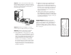
Installation guide

7
AHA-1520B Installation Guide
Part Number: 511162-00, Rev. A Page 7 of 16
Print Spec Number: 495339-00
Current Date: 5/30/96
Last Modified: May 30, 1996 3:43 pm
File Location: n:\mario\1520b_ig.nec\1520b_ig.frm
ECN Date: 6/11/95
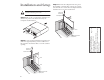
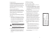
Setting Host Adapter Switches
The switch block on your host adapter, is factory set to
work in a Plug and Play system. Since resources in a
Plug and Play system are assigned automatically, you
should not have to change these settings.
If your system is not Plug and Play, you may have to
change the I/O port address and BIOS address settings.
The table below lists all possible settings on the switch
block.
■ Host Adapter BIOS Address—If your system is Plug
and Play, the BIOS address is set automatically. If
your system is not Plug and Play, you should choose
a BIOS address range that does not conflict with the
BIOS address range of another device installed in
your system.
In order to boot from a SCSI disk drive connected to
the host adapter, a BIOS address must be selected. If
you set the BIOS address to BIOS PROM Disabled (set
sw1, sw2 and sw3 to On), you disable all BIOS func-
tionality (including access to the SCSISelect utility at
system bootup) and you cannot boot from a SCSI disk
drive.
1
Do not use this setting in Legacy/Non-Plug and Play systems.
2
If you disable the BIOS PROM, you must run SCSISelect to synchronize
the host adapter’s resource table with your new selection. Synchroniza-
tion is automatically performed just by entering SCSISelect.
If you wish to disable BIOS functionality and still
have access to SCSISelect, do not disable the BIOS
PROM with the switches. Instead, change the Host
Adapter BIOS setting in SCSISelect to Disabled.
■ Host Adapter I/O Port Address—If your system is
Plug and Play, the I/O port address is set automati-
cally. If your system is not Plug and Play, you should
choose an I/O address range that does not conflict
with the I/O address range of another device installed
in your system.
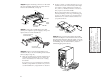
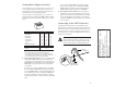
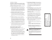
Connecting to the LED Connector
(Optional) Most computers have an LED disk activity
light on the front panel. If you disconnect the cable from
the LED connector on the motherboard and connect it to
the LED connector on the host adapter, the LED on the
front panel of the computer will light whenever there is
activity on the SCSI bus.
Note: If you are using non-SCSI disk drives (e.g.,
IDE), you may not want to connect your com-
puter’s LED to the host adapter, since the LED
will no longer indicate non-SCSI disk activity.
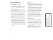
Host Adapter BIOS Address sw1 sw2 sw3
DC000-DFFFF Off Off Off
D8000-DBFFF On Off Off
D4000-D7FFF Off On Off
D0000-D3FFF On On Off
CC000-CFFFF Off Off On
C8000-CBFFF On Off On
Inactive
1
Off On On
BIOS PROM Disabled
2
On On On
Host Adapter I/O Port Address sw4
340-35F Off
140-15F On
(Open = Off)
1 2 3 4
OPEN
LED Connector
on Host Adapter
LED Cable
from Motherboard
Pin 1
1
2-pin
LED
Cable