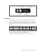
IBM Redbooks Paper David Watts Robert Moon IBM Eserver xSeries 366 Technical Introduction Delivering an industry-leading, 64-bit framework for mid-tier application development, the IBM Eserver® xSeries® 366 is built on the power of the IBM® eServer X3 Architecture, the third generation of IBM Enterprise X-Architecture™ technology. X3 Architecture drives the x366 to deliver the performance, availability, and manageability required for the next generation of industry-standard servers.
Overview of the x366 The key features of the x366 include: Four-way capable server in a rack-dense 3U form factor. IBM Eserver X3 Architecture, the XA-64e third-generation chipset. Models with one Intel® Xeon MP processor, up to 3.66 GHz and 1 MB L2 cache, which can be upgraded to four-way. Processors support 64-bit addressing with the Intel Extended Memory 64 Technology (EM64T) architecture. Memory: 2 GB standard expandable to 64 GB (with 4 GB DIMMs), using high-performance PC2-3200 ECC DDR2 DIMMs.
Dual-core capability: In addition to the single-core Xeon processors MP available today, strategic intent of IBM is to support dual-core microprocessor technology on the x366 server at such a time that this technology becomes generally available from our partners. The strategic intent also includes releasing a dual-core upgrade option kit to enable customers to upgrade from single-core to dual-core technology in the future.
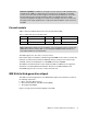
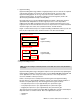
CPU 1 CPU 2 667 MHz 5.33 GBps DDR2 SMI2 DDR2 SMI2 DDR2 SMI2 DDR2 SMI2 Each: 667 MHz 5.33 GBps PCI-X bridge 33 66 CPU 4 667 MHz 5.33 GBps Memory controller 6 GBps Calgary CPU 3 IBM XA-64e core chipset Hurricane 6 GBps 6 GBps PCI-X bridge 266 266 MHz 266 MHz Video RSA SL 1 USB 2.0 ServeRAID South bridge Adaptec SAS EIDE K/M Serial 2 3 4 5 6 HDD backplane Gigabit Ethernet Six PCI-X 2.
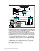
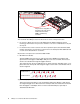
Service processor Ethernet port System serial port Service processor serial port 2x USB Mouse Keyboard Video 2x Gigabit Ethernet IXA RS-485 (not service processor) Figure 4 Rear view of the x366 Processors The x366 models use the Intel Xeon Processor MP with EM64T extensions (“Cranford”). Models of the x366 come with one processor installed. One, two, three, or four processors are supported. Installed processors must be identical in speed and cache size.
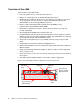
O FR 1 N T O FR 2 N T O FR 3 N T 4 The processor tray pulls out from the front of the server and houses the CPUs, VRMs, and memory controller. Figure 5 x366 processor tray The “Cranford” Xeon MP processor has two levels of cache on the processor die: L2 cache is 1 MB in size. The L2 cache implements the Advanced Transfer Cache technology, which means L2-to-processor transfers occur across a 256-bit bus in only one clock cycle.
Hyper-Threading Hyper-Threading Technology enables a single physical processor to execute two separate code streams (threads) concurrently. To the operating system, a processor with Hyper-Threading appears as two logical processors, each of which has its own architectural state (that is, its own data, segment, and control registers) and its own advanced programmable interrupt controller (APIC).
– Web servers – E-mail Note that Microsoft® licensing of the Windows 2000 Server operating systems is by number of processors (four-way for Server, eight-way for Advanced Server, 32-way for Datacenter Server). Therefore, the appearance of twice as many logical processors can potentially affect the installation of the operating system. Windows Server 2003 understands the concept of physical processors versus logical processors.
32-bit process on this system gets its very own 4 GB of physical memory space (provided sufficient physical memory is installed). This is already a huge improvement compared to IA32, where the operating system kernel and the application had to share 4 GB of physical memory. Additionally, the compatibility mode does not support the virtual 8086 mode, so real-mode legacy applications are not supported. However, 16-bit protected mode applications are supported.
The XceL4v also functions as a snoop filter lookup table to reduce traffic on the front side bus. Its embedded DRAM (eDRAM) stores a directory of all processor cache lines to minimize snoop traffic on the dual front-side buses and minimize cache misses. System memory The models of the x366 have a 2 GB standard, implemented as two 1 GB PC2-3200 ECC DDR2 DIMMs. Memory is implemented in the x366 using memory cards. Each card has four DIMM sockets.
When the cover and bezel are removed, the memory cards are easily accessible (Figure 8). In order to replace or add any DIMM, you need to remove the memory card. See “Memory mirroring” on page 13 and “Hot-add memory” on page 15, to see how this can be done even while the system and the operating system are up and running. Each memory card has four DIMM sockets. DIMMs must be installed in matched pairs. The x366 has one memory card standard and supports up to four cards.
A more detailed description and the exact sequence for installation can be found in the xSeries 366 User’s Guide. If you want to install the full 64 GB, you must remove the existing 1 GB DIMMs and fully populate the x366 with four memory cards, each with four 4 GB DIMMs.
by default.) Because all mirroring activities are handled by the hardware, memory mirroring is operating system independent. When memory mirroring is enabled, certain restrictions exist with respect to placement and size of memory DIMMs and the placement and removal of memory cards. These topics are discussed in “Memory mirroring” on page 13. Chipkill™ memory Chipkill is integrated into the XA-64e chipset, so it does not require special Chipkill DIMMs and is transparent to the operating system.
To understand what memory mirroring and hot-swap capabilities exist with the server, you must first understand how the memory cards are powered. The x366 has two separate memory power buses that are split between the four memory cards. As shown in Figure 9, memory cards 1 and 2 are on power bus 1, and memory cards 3 and 4 are on power bus 2.
To easily identify whether hot-swap is enabled and the status of power to the memory card, each memory card has a green memory hot-swap enable LED, and a green memory port power LED on the top panel of the memory card, as shown in Figure 9 on page 14. The memory card has eject levers with sensors, so that the system can recognize when a memory card is being removed and power down that card’s slot accordingly. The overall process to hot-swap a failed DIMM is as follows: 1.
For information about performing a hot-add operation, and more information about the restrictions, see the x366 User’s Guide. Notes: After you have added a memory card with two DIMMs, you cannot add more memory to that same memory card without powering off the server. Enabling hot-add reserves a portion of the memory map for the memory that may be hot-added in the future. If you do not plan to use hot-add, we recommend that you not enable this feature in BIOS.
SAS 1.0 technology is replacing Ultra320 SCSI in SCSI and RAID controllers. Beyond the upgrades in I/O processor and memory speeds, SAS-based products will differ from SCSI-based products in the following ways: Higher bandwidth Ultra320 SCSI supports 320 MBps of bandwidth per channel. SAS 1.0 supports 3 Gbps (approximately 300 MBps) of bandwidth per port.
See ServerProven® for the latest list of supported adapters and hot-swap SAS drives: http://www.pc.ibm.com/us/compat/xseries/controllers/matrix.html For a comparison of features of members of the ServeRAID family, see: http://www.redbooks.ibm.com/abstracts/tips0054.html PCI subsystem As shown in Figure 3 on page 4, there are six full-length hot-swap PCI-X 2.0 slots internal to the x366, and all are vacant in the standard models.
x366 PCI slots As shown in Figure 3 on page 4, there are six full-length 64-bit PCI-X slots. PCI slot 1 266 MHz 64-bit PCI-X slot 2 266 MHz 64-bit PCI-X slot 3 266 MHz 64-bit PCI-X slot 4 266 MHz 64-bit PCI-X slot 5 266 MHz 64-bit PCI-X slot 6 266 MHz 64-bit Figure 10 PCI-X slots The six slots all support hot-plug PCI-X 3.3 V, 32-bit or 64-bit PCI, and PCI-X 2.0 adapters. Further configuration information includes: Video adapters are not supported. The PCI slots support 3.3 V adapters only.
Includes dual onboard RISC processors for advanced packet parsing Offers backward compatibility with today's 10/100 network The Broadcom controller also includes software support for failover, layer-3 load balancing, and comprehensive diagnostics. Category 5 or better Ethernet cabling is required with RJ-45 connectors. If you plan to implement a Gigabit Ethernet connection, ensure that your network infrastructure is capable of the necessary throughput to match the server’s I/O capacity.
Four hot-swap fans (one redundant) Memory redundancy features: memory mirroring, Memory ProteXion, and ChipKill Hot-swap drive bays and optional ServeRAID-8i RAID controller offer redundancy Four hot-swap fans (one redundant) Two hot-swap power supplies (one redundant) Figure 11 Redundancy features of the x366 Light path diagnostics To limit the need to slide the server out of the rack to diagnose problems, a light path diagnostics panel is located at the front of the x366.
Power-control button USB connector Release latch - slide to the left and pull out to display the light path diagnostics panel Power-on LED Locator LED Light Path Diagnostics System error Hard disk drive activity Information LED OVER SPEC REMIND PS LINK CPU VRM LOG MEM NMI PCI SP DASD RAID NONRED TEMP PCI BRD CPU BRD FAN I/O BRD Figure 12 Light path diagnostic panel Baseboard Management Controller service processor The Baseboard Management Controller (BMC) is a small, independent micro
System initialization The BMC has I2C access to certain system components that may require initialization before power-up. System software state tracking The BMC monitors the system and reports when the BIOS and POST phases are complete and the operating system has booted. System event monitoring During runtime, the BMC continually monitors critical system items such as fans, power supplies, temperatures, and voltages. The system status is logged and reported to the service processor, if present.
– System-independent installation eliminates the need to install service processor drivers, helps save IT staff time, and reduces installation complexity. Remote diskette and CD-ROM drive support – Enables remote booting and software loading of the server for application or operating system installation and updates. – Performs configuration remotely; helps save IT time and money by reducing on-site presence and server downtime.
Table 4 x366 operating system support Operating system1 Release Available Hyper-Threading Windows 2000 Server SP4 Yes Yes Windows 2000 Advanced Server SP4 Yes Yes Windows Server 2003, Standard Edition Initial Yes Optimized Windows Server 2003, Enterprise Edition Initial Yes Optimized Windows Server 2003, Standard x64 Edition SP1 Yes Optimized Windows Server 2003, Enterprise x64 Edition SP1 Yes Optimized NetWare 6.
Operating system 32-bit legacy mode Compatibility mode 64-bit mode SUSE LINUX Enterprise Server for x86 Supported No No SUSE LINUX Enterprise Server for AMD64/EM64T No Supported Supported VMware ESX Server Supported No No The team that wrote this Redpaper This Redpaper was produced by a team of specialists from around the world working at the International Technical Support Organization, Raleigh Center. David Watts is a Consulting IT Specialist at the IBM ITSO Center in Raleigh.
Jocelyn Johnstone, ITS Service Development, WINTEL Platform, Greenock Randy Kolvick, xSeries 366 System Engineer, Raleigh John McAbel, WW Solutions Marketing Manager for xSeries, Beaverton Colin McKerrel, Global Solutions, Raleigh Jim Marschausen, WW SPORE Manager, xSeries Compatibility Lab Test Lead, Raleigh Rick Rudd, WW Brand Manager, Raleigh IBM Eserver xSeries 366 Technical Introduction 27
IBM Eserver xSeries 366 Technical Introduction
Notices This information was developed for products and services offered in the U.S.A. IBM may not offer the products, services, or features discussed in this document in other countries. Consult your local IBM representative for information on the products and services currently available in your area. Any reference to an IBM product, program, or service is not intended to state or imply that only that IBM product, program, or service may be used.
This document created or updated on October 12, 2005. ® Send us your comments in one of the following ways: Use the online Contact us review redbook form found at: ibm.com/redbooks Send your comments in an email to: redbook@us.ibm.com Mail your comments to: IBM Corporation, International Technical Support Organization Dept. HZ8 Building 662 P.O. Box 12195 Research Triangle Park, NC 27709-2195 U.S.A.