Serial Attached SCSI RAID Controllers Installation and User’s Guide PMC-Sierra PMC-SierraConfidential Confidential— —Preliminary PreliminaryDraft Draft10/21/11 10/21/11
● 2 Copyright Copyright © 2011 PMC-Sierra, Inc. All rights reserved. The information in this document is proprietary and confidential to PMC-Sierra, Inc., and for its customers’ internal use. In any event, no part of this document may be reproduced or redistributed in any form without the express written consent of PMCSierra, Inc. Trademarks PMC, PMC-Sierra, and Adaptec are registered trademarks of PMC-Sierra, Inc. “Adaptec by PMC” is a trademark of PMC-Sierra, Inc.
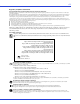
● 3 Adaptec by PMC Product Support If you have questions about installing or using your Adaptec by PMC product, check this document first—you will find answers to most of your questions. If you need further assistance, use the support options listed below. To expedite your service, have your computer in front of you. Technical Support Identification (TSID) Number ● Before contacting Technical Support, you need your product unique TSID number. The TSID number identifies your product and support status.
● 4 Limited 3-Year Hardware Warranty 1. PMC-Sierra, Inc. (“PMC-Sierra”) warrants to the purchaser of this product that it will be free from defects in material and workmanship for a period of three (3) years from the date of purchase.
● 5 Regulatory Compliance Statements Federal Communications Commission Radio Frequency Interference Statement WARNING: Changes or modifications to this unit not expressly approved by the party responsible for compliance could void the user’s authority to operate the equipment. This equipment has been tested and found to comply with the limits for a Class B digital device, pursuant to Part 15 of the FCC rules.
● Korean Compliance (KCC) Statement Adaptec by PMC products are tested and certified by KCC: KCC-REM-KHK-ASR-6xx5 The above certification covers the following series: ASR-6805, ASR-6445, ASR-6405 ASR-6805E, ASR-6405E, ASR-6805Q ASR-6805T, ASR-6405T, ASR-6805TQ This equipment is home use (Class B) electromagnetic wave suitability equipment and to be used mainly at home and it can be used in all areas. ! Caution: Risk of explosion if the battery is replaced by an incorrect type.
Contents 1 About This Guide What You Need to Know Before You Begin ................................................... 13 Terminology Used in this Guide ...................................................................... 13 How to Find More Information....................................................................... 13 2 Kit Contents and System Requirements Kit Contents ...................................................................................................... 15 System Requirements..
Contents ● 8 About the Adaptec RAID 6445......................................................................... 34 About the Adaptec RAID 6805/6805Q ............................................................ 35 About the Adaptec RAID 6405E ...................................................................... 36 About the Adaptec RAID 6805E ...................................................................... 37 About the Adaptec RAID 6405T ...........................................................
Contents ● 9 Installing with Red Hat Linux 6 or Fedora Linux ........................................... 62 Installing with SuSE Linux ............................................................................... 63 Installing with Debian Linux............................................................................ 63 Installing with Ubuntu Linux........................................................................... 65 Installing with Solaris.....................................................
Contents A ● 10 Introduction to SAS Terminology Used in This Chapter ................................................................. 89 What is SAS?...................................................................................................... 89 How Do SAS Devices Communicate?.............................................................. 90 What’s a Phy? .................................................................................................... 90 What’s a SAS Port?...................
Contents ● 11 Opening SerialSelect.................................................................................. 110 Applying Changes and Exiting................................................................. 110 Modifying Your Controller’s Configuration........................................... 110 Formatting and Verifying Disk Drives........................................................... 113 Locating Disk Drives.................................................................................
Contents F ● 12 Safety Information Electrostatic Discharge (ESD) ........................................................................ 147 G Technical Specifications Environmental Specifications......................................................................... 149 DC Power Requirements ................................................................................ 149 Current Requirements ..................................................................................
About This Guide 1 In this chapter... What You Need to Know Before You Begin .......................................................................... 13 Terminology Used in this Guide............................................................................................ 13 How to Find More Information ............................................................................................ 13 This Installation and User’s Guide explains how to install your Adaptec® by PMC™ RAID controller.
Chapter 1: About This Guide ● 13 What You Need to Know Before You Begin You should be familiar with computer hardware, data storage, RAID technology, and SAS and Serial ATA (SATA) technology. (For an introduction to SAS, see page 88.) You should also be familiar with Direct-Attached Storage (DAS) concepts and technology. Note: Because this guide covers multiple Adaptec RAID products, some of the features and functions described may not be available for your controller.
Kit Contents and System Requirements 2 In this chapter... Kit Contents............................................................................................................................ 15 System Requirements ............................................................................................................. 15 This chapter lists the contents of your Adaptec RAID controller kit and the system requirements that must be met for you to successfully install and use your controller.
Chapter 2: Kit Contents and System Requirements ● 15 Kit Contents ● Adaptec by PMC RAID controller ● Adaptec Installation DVD (bootable), including controller drivers, Adaptec Storage Manager, ARCCONF command line utility, and documentation ● Cables (Not all kits contain cables. If your kit does, the type and quantity vary—for cable information about your controller, visit the Adaptec Web site at www.adaptec.com.
Chapter 2: Kit Contents and System Requirements ● 16 ● DVD-ROM drive ● Floppy disk drive, USB flash drive, or CD burner, for creating driver disks and bootable media
About Your RAID Controller 3 In this chapter... Standard RAID Controller Features ...................................................................................... 18 Adding a Battery Backup Module ......................................................................................... 19 Adding a Flash Backup Module............................................................................................. 19 About the Adaptec RAID 5085 ............................................................
Chapter 3: About Your RAID Controller ● 18 Standard RAID Controller Features ● Support for SAS disk drives, SATA/SATA II disk drives, and SATA and SAS Solid State Drives (SSDs) ● Flash ROM for updates to controller firmware, BIOS, and the Adaptec RAID Configuration utility ● Disk drive hot-swapping ● Event logging and broadcasting including email and SNMP messages ● Multiple options for creating and managing RAID arrays—A full software application (Adaptec Storage Manager), a BIOS-based utility
Chapter 3: About Your RAID Controller ● 19 Advanced Data Protection Suite Note: The following features are supported on Adaptec Series 5 and Series 6 controllers. Striped Mirrors are also supported on Series 2 and Series 6E controllers. ● Copyback Hot Spare—You can use this feature to move data from a hot spare back to its original location after a failed disk drive is replaced.
Chapter 3: About Your RAID Controller ● 20 About the Adaptec RAID 5085 The Adaptec RAID 5085 is a SAS RAID controller with these features: Ext. Alarm Aggregate Activity Mode 0 Flash connector Drive Activity LEDs Diagnostic LEDs Audible Alarm Drive Activity LED connectors for CN1/CN0 CN0 CN1 2 external SAS connectors Battery connector PCIe x8 connector Mounting bracket Form Factor Low-profile MD2 Bus compatibility PCIe 1.
Chapter 3: About Your RAID Controller ● About the Adaptec RAID 5405 The Adaptec RAID 5405 is a SAS RAID controller with these features: Drive Activity LED connectors for CN0 Drive Activity LEDs for CN0 Mode 0 Flash connector Aggregate Activity Diagnostic LEDs Internal mini-SAS connector CN0 Status CN0 I2C connector for CN0 PCIe x8 connector Battery connector Mounting bracket Ext. Alarm connector Form Factor Low-profile MD2 Bus compatibility PCIe 1.
Chapter 3: About Your RAID Controller ● 22 About the Adaptec RAID 5445 The Adaptec RAID 5445 is a SAS RAID controller with these features: Drive Activity CN1/CN0 Status CN1/CN0 Mode 0 Flash connector Ext. Alarm Diagnostic LEDs (back of card) Internal mini-SAS connector CN0 Battery connector External miniSAS connector CN1 Audible Alarm I2C connector for CN0 PCIe x8 connector Aggregate Activity Mounting bracket Form Factor Low-profile MD2 Bus compatibility PCIe 1.
Chapter 3: About Your RAID Controller ● 23 About the Adaptec RAID 5805/5805Q The Adaptec RAID 5805/5805Q is a SAS RAID controller with these features: Drive Activity LED connectors for CN0/CN1 Drive Activity LEDs for CN0/CN1 Mode 0 Flash connector Aggregate Activity Diagnostic LEDs CN1 2 internal mini-SAS connectors CN0 Status CN1, CN0 I2C connector for CN1 I2C connector for CN0 PCIe x8 connector Battery connector Mounting bracket Ext.
Chapter 3: About Your RAID Controller ● 24 About the Adaptec RAID 51245 The Adaptec RAID 51245 is a SAS RAID controller with these features: Mode 0 Flash I2C, CN2 Activity CN2 I2C, CN1 I2C, CN0 CN0 Activity CN0, CN1 CN1 CN6 CN2 3 internal mini-SAS connectors 1 external mini-SAS connector Battery connector Reserved Ext. Alarm Aggregate Activity Form Factor Full Height, Half Length Bus compatibility PCIe 1.
Chapter 3: About Your RAID Controller ● 25 About the Adaptec RAID 51645 The Adaptec RAID 51645 is a SAS RAID controller with these features: Mode 0 Flash Activity CN2, CN3 I2C, CN2 I2C, CN3 I2C, CN1 I2C, CN0 CN0 Activity CN0, CN1 CN1 CN6 CN2 4 internal mini-SAS connectors CN3 1 external mini-SAS connector Battery connector Reserved Ext. Alarm Aggregate Activity Form Factor Full Height, Half Length Bus compatibility PCIe 1.
Chapter 3: About Your RAID Controller ● 26 About the Adaptec RAID 52445 The Adaptec RAID 52445 is a SAS RAID controller with these features: I2C, CN2 I2C, CN3 I2C, CN4 I2C, CN5 Mode 0 Flash connector I2C, CN1 I2C, CN0 Activity CN2, CN3 CN4 CN5 CN0 Activity CN0, CN1 CN1 CN2 CN6 1 external mini-SAS connector CN3 6 internal mini-SAS connectors Battery connector Reserved Ext. Alarm Aggregate Activity Activity CN4, CN5 Form Factor Full Height, Half Length Bus compatibility PCIe 1.
Chapter 3: About Your RAID Controller About the Adaptec RAID 5405Z The Adaptec RAID 5405Z is a SAS RAID controller with these features: Drive Activity LED connectors for CN0 Drive Activity LEDs for CN0 I2C connector for CN0 Ext. Alarm connector Aggregate Activity Mode 0 Flash connector Diagnostic LEDs Internal mini-SAS connector CN0 PCIe x8 connector ZMM-100CC Supercapacitor connector ZMM-100DB Daughterboard Mounting bracket Form Factor Low-profile MD2 Bus compatibility PCIe 1.
Chapter 3: About Your RAID Controller ● 28 About the Adaptec RAID 5445Z The Adaptec RAID 5445Z is a SAS RAID controller with these features: Drive Activity LED connectors for CN0/CN1 Drive Activity LEDs for CN0/CN1 I2C connectors for CN0/CN1 Ext.
Chapter 3: About Your RAID Controller ● 29 About the Adaptec RAID 5805Z/5805ZQ The Adaptec RAID 5805Z/5805ZQ is a SAS RAID controller with these features: Drive Activity LED connectors for CN0/CN1 Drive Activity LEDs for CN0/CN1 I2C connectors for CN0/CN1 Ext.
Chapter 3: About Your RAID Controller About the Adaptec RAID 2045 The Adaptec RAID 2045 is a SAS RAID controller with these features: Aggregate Activity Mode 0 Flash connector CN1 1 external miniSAS connector PCIe x8 connector Mounting bracket Form Factor Low-profile MD2 Bus compatibility PCIe 1.
Chapter 3: About Your RAID Controller ● 31 About the Adaptec RAID 2405/2405Q The Adaptec RAID 2405/2405Q is a SAS RAID controller with these features: Drive Activity LED connector for CN0 Aggregate Activity Mode 0 Flash connector Internal mini-SAS connector CN0 I2C, CN0 PCIe x8 connector Mounting bracket Form Factor Low-profile MD2 Bus compatibility PCIe 1.
Chapter 3: About Your RAID Controller ● About the Adaptec RAID 2805 The Adaptec RAID 2805 is a SAS RAID controller with these features: Drive Activity LED connector for CN0/CN1 Aggregate Activity Mode 0 Flash connector Internal mini-SAS connector CN1 Internal mini-SAS connector CN0 I2C, CN0 I2C, CN1 PCIe x8 connector Mounting bracket Form Factor Low-profile MD2 Bus compatibility PCIe 1.
Chapter 3: About Your RAID Controller About the Adaptec RAID 6405 The Adaptec RAID 6405 is a SAS RAID controller with these features: Drive Activity LED connector for CN0 I2C connector for CN0 Ext.
Chapter 3: About Your RAID Controller ● 34 About the Adaptec RAID 6445 The Adaptec RAID 6445 is a SAS RAID controller with these features: Drive Activity LED connector for CN0 I2C connector for CN0 Ext.
Chapter 3: About Your RAID Controller ● 35 About the Adaptec RAID 6805/6805Q The Adaptec RAID 6805/6805Q is a SAS RAID controller with these features: Drive Activity LED connector for CN0/CN1 I2C connector for CN1 I2C connector for CN0 Ext.
Chapter 3: About Your RAID Controller About the Adaptec RAID 6405E The Adaptec RAID 6405E is a SAS RAID controller with these features: Drive Activity LED connector for CN0 HDA mode connector Ext. Alarm connector Aggregate Activity PCIe x1 connector Internal mini-SAS connector CN0 Mounting bracket Form Factor Low-profile MD2 (reduced length: 5.
Chapter 3: About Your RAID Controller ● 37 About the Adaptec RAID 6805E The Adaptec RAID 6805E is a SAS RAID controller with these features: Drive Activity LED connector for CN0/CN1 HDA mode connector Ext. Alarm connector Aggregate Activity CN1 CN0 2 internal mini-SAS connectors PCIe x4 connector Mounting bracket Form Factor Low-profile MD2 (reduced length: 6.
Chapter 3: About Your RAID Controller About the Adaptec RAID 6405T The Adaptec RAID 6405T is a SAS RAID controller with these features: Internal mini-SAS connector CN0 Drive Activity LED connector for CN0 Diagnostic/Activity LEDs Ext.
Chapter 3: About Your RAID Controller ● 39 About the Adaptec RAID 6805T/6805TQ The Adaptec RAID 6805T/6805TQ is a SAS RAID controller with these features: 2 internal mini-SAS connectors Drive Activity LED connector for CN0/CN1 Diagnostic/Activity LEDs Ext.
Getting Started 4 In this chapter... Choosing a RAID Level.......................................................................................................... 41 Selecting Disk Drives and Cables .......................................................................................... 42 Replacing the Full-Height Bracket with a Low-Profile Bracket ........................................... 43 Installation Options .....................................................................................
Chapter 4: Getting Started ● 41 Choosing a RAID Level This section provides a brief overview of the RAID levels supported by your Adaptec RAID controller, including the minimum and maximum number of disk drives required by each. Note: Before you begin, familiarize yourself with your controller’s physical features and the RAID levels that it supports (see Standard RAID Controller Features on page 18). ● RAID 0 (Non-redundant Array)—Stripes data across multiple disk drives.
Chapter 4: Getting Started ● 42 Selecting Disk Drives and Cables Disk Drives Your SAS controller supports SAS disk drives, SATA disk drives, and SATA and SAS Solid State Drives (SSDs). When selecting disk drives for your RAID array, ensure that all the disk drives have the same performance level. You can use different-sized disk drives in the array, but the array will be limited to the capacity of the smallest and slowest disk drive.
Chapter 4: Getting Started ● 43 External mini-SAS to mini-SAS (SFF-8088 to SFF-8088)— Connects to a backplane or enclosure. Internal mini-SAS to mini-SAS (SFF-8087 to SFF-8087)— Connects to a backplane or enclosure. Cable connectors are keyed so that you can’t insert them incorrectly. We recommend using only Adaptec SAS cables. For more information or to purchase cables, visit the Adaptec Web site at www.adaptec.com.
Chapter 4: Getting Started ● 44 To replace the full-height bracket with the low-profile bracket: 1 Remove the full-height bracket from the controller board. The full-height bracket is installed on the front side of the controller, with the mounting screws inserted from the back of the controller, as shown in the Figure 1. Using a Phillips head screw driver, remove the mounting screws, as shown in Figure 2, then set the screws aside for use in Step 2.
Chapter 4: Getting Started ● 45 Installation Options When you install your Adaptec RAID controller, you can choose to create a bootable array and then install your operating system and the controller driver on that array. Alternatively, you can complete a standard installation, where the controller driver is installed on an existing operating system. Basic Installation Steps This section describes the installation process. Follow the steps for the installation option you’ve chosen.
Installing the Controller and Disk Drives 5 In this chapter... Before You Begin .................................................................................................................... 47 Installing the Controller......................................................................................................... 47 Connecting Disk Drives to Your Controllers ........................................................................ 50 Connecting External Devices.............................
Chapter 5: Installing the Controller and Disk Drives ● 47 Before You Begin ● Read Safety Information on page 147. ● Familiarize yourself with your RAID controller’s physical features and the RAID levels that it supports (see page 18). ● Ensure you have the right quantity of disk drives for the RAID level you want to use for your arrays (see page 42). ● Ensure that you have the proper cables for your controller and disk drives (see page 42).
Chapter 5: Installing the Controller and Disk Drives 3 As shown at right, insert the RAID controller into the expansion slot and press down gently but firmly until it clicks into place. When installed properly, the RAID controller should appear level with the expansion slot. 4 Secure the bracket in the expansion slot, using the retention device (for instance, a screw or lever) supplied with your computer.
Chapter 5: Installing the Controller and Disk Drives ● 49 3 As shown at right, insert the RAID controller into the expansion slot and press down gently but firmly until it clicks into place. When installed properly, the RAID controller should appear level with the expansion slot. 4 Secure the bracket in the expansion slot, using the retention device (for instance, a screw or lever) supplied with your computer.
Chapter 5: Installing the Controller and Disk Drives ● 50 Connecting Disk Drives to Your Controllers You can connect SAS disk drives, SATA disk drives, and SATA and SAS Solid State Drives (SSDs) to your Adaptec RAID controller. (See www.adaptec.com/compatibility for a list of compatible drives.) There are no jumpers or switches to set before installation. If you plan to build a bootable array, ensure you install at least the minimum number disk drives required to support the RAID level you want.
Chapter 5: Installing the Controller and Disk Drives 3 ● 51 When all internal disk drives have been installed and attached to the controller, close your computer cabinet, reattach the power cord, then continue with Connecting External Devices on page 53. Connecting Drives to a System Backplane In a backplane connection, disk drives and SAS cards are attached to and communicate with each other through a system backplane.
Chapter 5: Installing the Controller and Disk Drives ● 52 Connecting Solid State Drives (SSDs) To connect a Solid State Drive to your controller, use a direct-attached connection or a backplane connection. If your server does not have a standard 2.5-inch drive tray, you must use a bracket/SLED which enables the SSD to fit properly. Note: For Adaptec maxCache applications or hybrid RAID arrays (comprised of hard drives and SSDs) you can use any Solid State Drive on the compatibility list. See www.adaptec.
Chapter 5: Installing the Controller and Disk Drives 2 ● 53 Use an internal mini-SAS to SATA cable to attach the SSD(s) to the controller, as shown in the following example. To other SSDs Internal x4 mini-SAS connector Single-port connector SSD connected to controller with internal mini-SAS to SATA Fanout cable (SFF-8087 to 4x-SATA) 3 When all SSDs have been installed and connected, close your computer cabinet, reattach the power cord, then continue with Connecting External Devices on page 53.
Creating a Bootable Array 6 In this chapter... Setting the Boot Controller.................................................................................................... 55 Creating an Array ................................................................................................................... 55 Making Your Array Bootable .................................................................................................
Chapter 6: Creating a Bootable Array ● 55 Setting the Boot Controller Note: If your system won’t contain more than one bootable controller, skip to the next section, Creating an Array. Your Adaptec RAID controller supports bootable disk drives and bootable arrays. To enable your system to boot from either a disk drive or an array connected to your controller: 1 Enter the system setup. 2 Navigate to the drive boot sequence. 3 Move the boot controller to the top of the list.
Chapter 6: Creating a Bootable Array ● 56 4 Select Initialize Drives, then press Enter. 5 Select at least three disk drives for the array, press Insert for each selected disk drive, then press Enter. ! Caution: During initialization, all data is deleted from the disk. Before continuing, back up any data you want to keep. 6 Press Y, then press Enter. The selected disk drives are initialized, then the ACU screen appears. 7 Select Create Array, then press Enter.
Chapter 6: Creating a Bootable Array ● 57 Creating an Array with Adaptec Storage Manager This section describes how to use the Adaptec Storage Manager configuration wizard to build a RAID 5 array. Note: You will need the Adaptec Installation DVD to complete this task. To create a RAID 5 array: 1 Insert the Adaptec Installation DVD into your DVD drive, then restart your computer. 2 When prompted, select the language you want, then press Enter. 3 Review the license information, then press Enter.
Chapter 6: Creating a Bootable Array 7 ● 58 Review the information that is displayed. Note: In DAS environments, Adaptec Storage Manager uses the term logical drives when referring to arrays (see page 13). In this example, Adaptec Storage Manager has used thirteen equal-sized disk drives to automatically create one logical drive with RAID 5 and a hot spare.
Installing the Driver and an Operating System 7 In this chapter... Before You Begin .................................................................................................................... 60 Creating a Driver Disk ........................................................................................................... 60 Installing with Windows ........................................................................................................ 61 Installing with Red Hat Linux 5........
Chapter 7: Installing the Driver and an Operating System ● 60 Before You Begin ● Install and connect your Adaptec RAID controller and internal disk drives (see page 46). ● Create a bootable array (see page 54). ● Create a driver disk (see the following section). Note: Not all operating systems are supported on all controllers. For up-to-date operating system version support, visit the Adaptec Web Site at www.adaptec.com. From the main menu select Support>Knowledgebase>Find Answers.
Chapter 7: Installing the Driver and an Operating System ● 61 Installing with Windows Note: You will need your Windows Installation CD to complete this task. Installing with Windows Server 2003 To install the Adaptec RAID controller driver while installing Windows: 1 Insert your Windows CD, then restart the computer. 2 Follow the on-screen instructions to begin the Windows installation. 3 When prompted to install a third-party driver, press F6.
Chapter 7: Installing the Driver and an Operating System ● 62 Installing with Red Hat Linux 5 Note: You will need your Red Hat 5 Installation CD to complete this task. To install the Adaptec RAID controller driver while installing Red Hat Linux 5: 1 Insert the first Red Hat Installation CD. 2 Restart your computer. 3 When the Red Hat Welcome screen appears, type linux dd at the Boot: prompt. 4 When prompted, insert the driver disk, then select OK.
Chapter 7: Installing the Driver and an Operating System 8 ● 63 Type the following commands to complete the driver installation: mkdir /mnt/sysimage/tmp/AACRAID cp -r /AACRAID/* /mnt/sysimage/tmp/AACRAID chroot /mnt/sysimage/ cd /tmp/AACRAID sh ./fc-post-install.sh exit 9 Press ALT+F6 to switch back to the installation screen, finish the installation, then reboot. 10 Continue with Managing Your Storage Space on page 79.
Chapter 7: Installing the Driver and an Operating System b ● 64 Insert and mount a USB flash drive: mount /dev/sda1 /mnt/aacraid-driver c Change to the Linux driver directory on the Adaptec Installation DVD, locate the .tgz archive file for your Debian operating system version (32-bit or 64-bit), then extract the contents of the archive to a temporary location.
Chapter 7: Installing the Driver and an Operating System ● 65 11 Type the following commands to complete the driver installation: For Debian 32-bit: cp -f /AACRAID/aacraid.ko-POST_MOD /target/lib/modules/2.6.26-2-686/kernel/ drivers/scsi/aacraid/aacraid.ko chroot /target /sbin/depmod -a 2.6.26-2-686 update-initramfs -u -v exit For Debian 64-bit: cp -f /AACRAID/aacraid.ko /target/lib/modules/2.6.26-2-amd64/kernel/drivers/ scsi/aacraid/aacraid.ko chroot /target /sbin/depmod -a 2.6.
Chapter 7: Installing the Driver and an Operating System 5 ● 66 Type the following commands to begin loading the driver: mkdir /mnt2 /AACRAID mount /dev/sda1 /mnt2 cp -R /mnt2/* /AACRAID umount /mnt2 6 Copy the driver file to the /lib/modules directory: cp -f /AACRAID/aacraid.ko-PRE_MOD /lib/modules/2.6.-generic/kernel/ drivers/scsi/aacraid/aacraid.ko where is 32-24 for Ubuntu 10.x and 38-8 for Ubuntu 11.x. 7 Remove the USB drive.
Chapter 7: Installing the Driver and an Operating System ● 67 Installing with Solaris Note: This task is not necessary if you are installing Solaris 10 Update 2 or later. Instead, you can choose to install Solaris using the in-box driver and update it either during or after the installation is complete, if required. Note: For systems without a floppy drive, you can create a driver disk by burning a CD with the aac_solaris-x86.iso file, available on the Adaptec Installation DVD.
Chapter 7: Installing the Driver and an Operating System ● 68 5 Select Yes to install a custom driver, then click Add. 6 Insert the driver disk, then click OK. 7 Select the driver from the displayed list, click OK, then follow the on-screen instructions to load the driver. 8 Complete the VMware installation, following the on-screen instructions. 9 Reboot your computer, then remove the VMware Installation CD.
Chapter 7: Installing the Driver and an Operating System 4 ● 69 Download the VMware ESXi5.0 Standard Software Depot (for example, vmware-ESXi5.0.0-469512-depot.zip) and store in a temporary location on your Windows build machine. You can download the software depot from the VMware Download Center at www.vmware.com/downloads; when you start the download, be sure to choose “ESXi Offline Bundle”. Note: You may need to provide account credentials to download the software depot from the VMware Web site.
Chapter 7: Installing the Driver and an Operating System f ● 70 Create a copy of the standard image profile, using the -CloneProfile option: # New-EsxImageProfile -CloneProfile ESXi-5.0.0-469512-standard -Name "ESXi 5.0 Adaptec Series 6" g Change the vendor and acceptance level of the new image profile: # Set-EsxImageProfile -ImageProfile "ESXi 5.
Chapter 7: Installing the Driver and an Operating System ● 71 Installing with FreeBSD Note: You will need your FreeBSD Installation CD to complete this task. To install the Adaptec RAID controller driver when installing FreeBSD: 1 Insert the FreeBSD Installation CD. 2 Restart your computer. 3 When the FreeBSD start screen opens, select 6 to escape to loader prompt. 4 Type load kernel. 5 Insert the driver floppy disk. 6 Type this command: load disk0:aacu.
Installing the Driver on an Existing Operating System 8 In this chapter... Before You Begin .................................................................................................................... 73 Creating a Driver Disk ........................................................................................................... 73 Installing on Windows ...........................................................................................................
Chapter 8: Installing the Driver on an Existing Operating System ● 73 Before You Begin Before you begin, install and connect your Adaptec RAID controller and internal disk drives (see page 46). You must also create a driver disk before you begin installing the controller driver. Note: Not all operating systems are supported on all controllers. For up-to-date operating system version support, visit the Adaptec Web Site at www.adaptec.com. From the main menu select Support>Knowledgebase>Find Answers.
Chapter 8: Installing the Driver on an Existing Operating System ● 74 Installing on Windows Follow the instructions in this section for your version of Windows. Installing on Windows Server 2003 To install the driver on Windows: 1 Start or restart Windows. The Found New Hardware Wizard opens and searches for the driver. 2 Insert the driver disk, select Floppy drive, then click Next. 3 Click Next, then click Next again. 4 Follow the on-screen instructions to complete the driver installation.
Chapter 8: Installing the Driver on an Existing Operating System ● Installing on Debian Linux Note: You must have root privileges to install the driver image. For Debian Linux, the su command is sufficient. To install the driver on Debian Linux: 1 Insert and mount the Debian Installation DVD: mount /dev/cdrom /mnt/cdrom 2 Load the Debian unpacking tools: apt-get install build-essential 3 Install the DEB driver package: For Debian Linux 5.x: dpkg -i aacraid-Debian+Ubuntu-all.deb For Debian Linux 6.
Chapter 8: Installing the Driver on an Existing Operating System ● 76 Installing on Solaris To install the driver on Solaris: 1 Start your computer. 2 (Solaris 10 only) Check for any pre-existing Adaptec driver by performing a pkginfo SUNWaac in a terminal window . If there is no pre-existing Adaptec driver on your computer, continue with Step 3. If an Adaptec driver is already installed on your computer, perform a pkgrm SUNWaac to remove it.
Chapter 8: Installing the Driver on an Existing Operating System 2 ● 77 Using a remote copy utility, copy the driver VIB file for your operating system version from the Linux driver folder on the installation DVD to a local directory on the ESX server. This example uses Linux scp to copy the driver to /tmp/aacraid: VMware ESX 4: scp /mnt/cdrom/linux/driver/vmware-esx-drivers-scsi-aacraid-400.4.1.7.283001.0.4.260247.x86_64.
Chapter 8: Installing the Driver on an Existing Operating System Installing on FreeBSD To install the driver on FreeBSD: 1 Start your computer. 2 Insert and mount the driver disk: mount -t msdos /dev/fd0 /mnt 3 Copy the driver package to the /tmp directory: cp /mnt/aac8x-i386.tgz /tmp 4 Install the driver package: pkg_add /tmp/aac8x-i386.tgz 5 Remove the driver disk, then reboot your computer. 6 Continue with Managing Your Storage Space on page 79.
Managing Your Storage Space 9 In this chapter... About Adaptec Storage Manager........................................................................................... 80 About the Adaptec RAID Controller Configuration Utility ................................................ 80 About the Adaptec RAID Configuration Utility................................................................... 81 About the Adaptec Flash Utility .................................................................................
Chapter 9: Managing Your Storage Space ● 80 About Adaptec Storage Manager Adaptec Storage Manager is a full-featured software application that helps you build a storage space for your online data, using Adaptec RAID controllers and disk drives. With Adaptec Storage Manager, you can group disk drives into logical drives and build in redundancy to protect your data and improve system performance.
Chapter 9: Managing Your Storage Space ● 81 About the Adaptec RAID Configuration Utility The Adaptec RAID Configuration (ARC) utility is a BIOS-based utility that you can use to create and manage controllers, disk drives and other devices, and arrays. The ARC utility comprises these tools: ● Array Configuration Utility (ACU)—For creating and managing arrays, and initializing and rescanning disk drives. ● SerialSelect—For modifying your controller and disk drive settings.
Chapter 9: Managing Your Storage Space ● ● 82 Additionally, you can use the ARCCONF command line utility to configure and manage arrays from the VMware ESX console. For information on installing the Adaptec Storage Manager Agent and ARCCONF on VMware ESX 4.x systems, see the Adaptec Storage Manager User’s Guide and the Command Line Utility User’s Guide, included on the installation DVD. ● On VMware ESXi 5.0 and VMware ESXi 4.
Solving Problems 10 In this chapter... Troubleshooting Checklist ..................................................................................................... 84 Silencing the Alarm ................................................................................................................ 84 Recovering from a Disk Drive Failure ................................................................................... 85 Resetting the Controller.......................................................
Chapter 10: Solving Problems ● 84 Troubleshooting Checklist If you encounter difficulties installing or using your Adaptec RAID controller, check these items first: ● With your computer powered off, check the connections to each disk drive, power supply, LED connector, and so on. Try disconnecting and reconnecting disk drives from the Adaptec RAID controller. ● Check that your Adaptec RAID controller is installed in a compatible PCIe expansion slot.
Chapter 10: Solving Problems ● 85 Recovering from a Disk Drive Failure This section explains how to recover when a disk drive fails: ● If the array was protected by a hot spare (see page 85). ● If the array was not protected by a hot spare (see page 85). ● If there is a disk drive failure in more than one array simultaneously (see page 85). ● If it is a RAID 0 array (see page 86). ● If multiple disk drives fail within the same array (see page 86).
Chapter 10: Solving Problems ● 86 If there are more disk drive failures than hot spares, see Failed Disk Drive Not Protected by a Hot Spare. If copyback is enabled, data is moved back to its original location once the controller detects that the failed drive has been replaced. Disk Drive Failure in a RAID 0 Array Because RAID 0 volumes do not include redundancy, if a disk drive fails in a RAID 0 array, the data can’t be recovered. Correct the cause of the failure or replace the failed disk drives.
Chapter 10: Solving Problems 3 ● 87 Copy the file AFU.exe (from the Adaptec Installation DVD) and the firmware image files (typically *.ufi) to a bootable DOS floppy disk, USB flash drive, or writable CD-ROM. Note: Due to space limitations with floppy disks, you may need to create multiple floppy disks for each firmware image. 4 Power off your computer, disconnect the power cord, then open the cabinet following the manufacturer’s instructions.
Introduction to SAS A In this appendix... Terminology Used in This Chapter ....................................................................................... 89 What is SAS? ........................................................................................................................... 89 How Do SAS Devices Communicate? ................................................................................... 90 What’s a Phy? ......................................................................
Appendix A: Introduction to SAS ● 89 Terminology Used in This Chapter For convenience, SAS HBAs and SAS RAID controllers are referred to generically in this chapter as SAS cards. HBAs, RAID controllers, disk drives, and external disk drive enclosures are referred to as end devices and expanders are referred to as expander devices. For convenience, this chapter refers to end devices and expander devices collectively as SAS devices.
Appendix A: Introduction to SAS ● 90 How Do SAS Devices Communicate? SAS devices communicate with each other through links. A link is a physical connection between two phys. As shown in the following figure, SAS devices contain ports (see page 91), ports contain phys, and each phy contains one transmitter and one receiver—one transceiver. A phy can belong to one port only.
Appendix A: Introduction to SAS ● 91 What’s a SAS Port? Note: Because the physical link between SAS devices is from phy to phy, rather than port to port, a “port” is more of a virtual concept, different from what is normally considered a port on other types of RAID controllers and storage devices. A port is one or more phys. A narrow port contains one phy. A wide port typically contains four phys.
Appendix A: Introduction to SAS ● 92 How are Disk Drives Identified in SAS? In the BIOS and in the management utilities (see Identifying Disk Drives on page 114), disk drives are identified in the following formats: ● CNX:DevY = Device Y is attached to Connector X (see Direct-attach Connections below for more information) ● BoxX:SlotX = Enclosure X is attached to a disk drive in Slot X (see Backplane Connections below for more information) ● ExpX:PhyX = Expander X is attached to Phy X (see SAS Expan
Appendix A: Introduction to SAS ● 93 Some backplanes support daisy-chain expansion to other backplanes. For example, you can daisy-chain (connect one to the next) up to nine Adaptec S50 enclosures to a single SAS card in a host system. SAS Expander Connections A SAS expander device literally expands the number of end devices that you can connect together.
Appendix A: Introduction to SAS ● 94 How is SAS Different from Parallel SCSI? In summary, although SAS and parallel SCSI both use the SCSI command set, how they move data from one place to another is very different. To support point-to-point serial data transport, SAS introduces new types of connectors, cables, connection options, and terminology. Generally speaking, SAS is faster and more flexible than parallel SCSI, and provides more options for building your storage space.
Understanding RAID B In this appendix... Understanding Drive Segments............................................................................................. 96 Non-redundant Arrays (RAID 0) .......................................................................................... 96 RAID 1 Arrays ........................................................................................................................ 97 RAID 1 Enhanced Arrays...........................................................
Appendix B: Understanding RAID ● 96 Understanding Drive Segments A drive segment is a disk drive or portion of a disk drive that is used to create an array. A disk drive can include both RAID segments (segments that are part of an array) and available segments. Each segment can be part of only one logical device at a time. If a disk drive is not part of any logical device, the entire disk is an available segment.
Appendix B: Understanding RAID ● 97 RAID 1 Arrays A RAID 1 array is built from two disk drives, where one disk drive is a mirror of the other (the same data is stored on each disk drive). Compared to independent disk drives, RAID 1 arrays provide improved performance, with twice the read rate and an equal write rate of single disks. However, capacity is only 50 percent of independent disk drives.
Appendix B: Understanding RAID ● 98 RAID 10 Arrays A RAID 10 array is built from two or more equal-sized RAID 1 arrays. Data in a RAID 10 array is both striped and mirrored. Mirroring provides data protection, and striping improves performance. Drive segment size is limited to the size of the smallest disk drive in the array.
Appendix B: Understanding RAID ● 99 RAID 5 Arrays A RAID 5 array is built from a minimum of three disk drives, and uses data striping and parity data to provide redundancy. Parity data provides data protection, and striping improves performance. Parity data is an error-correcting redundancy that’s used to re-create data if a disk drive fails. In RAID 5 arrays, parity data (represented by Ps in the next figure) is striped evenly across the disk drives with the stored data.
Appendix B: Understanding RAID ● 100 RAID 5EE Arrays A RAID 5EE array—also known as a hot space—is similar to a RAID 5 array except that it includes a distributed spare drive and must be built from a minimum of four disk drives. Unlike a hot spare, a distributed spare is striped evenly across the disk drives with the stored data and parity data, and can’t be shared with other logical disk drives. A distributed spare improves the speed at which the array is rebuilt following a disk drive failure.
Appendix B: Understanding RAID ● 101 RAID 50 Arrays A RAID 50 array is built from six to forty-eight disk drives configured as two or more RAID 5 arrays, and stripes stored data and parity data across all disk drives in both RAID 5 arrays. (For more information, see RAID 5 Arrays on page 99.) The parity data provides data protection, and striping improves performance. RAID 50 arrays also provide high data transfer speeds. Drive segment size is limited to the size of the smallest disk drive in the array.
Appendix B: Understanding RAID ● 102 RAID 6 Arrays A RAID 6 array—also known as dual drive failure protection—is similar to a RAID 5 array because it uses data striping and parity data to provide redundancy. However, RAID 6 arrays include two independent sets of parity data instead of one. Both sets of parity data are striped separately across all disk drives in the array. RAID 6 arrays provide extra protection for your data because they can recover from two simultaneous disk drive failures.
Appendix B: Understanding RAID ● 103 Selecting the Best RAID Level Use this table to select the RAID levels that are most appropriate for the logical drives on your storage space, based on the number of available disk drives and your requirements for performance and reliability.
Using the Adaptec RAID Configuration Utility C In this appendix... Introduction to the ARC Utility .......................................................................................... 105 Running the ARC Utility...................................................................................................... 105 Using the ACU to Create and Manage Arrays .................................................................... 105 Using the ACU to Create and Manage JBODs..............................
Appendix C: Using the Adaptec RAID Configuration Utility ● 105 Introduction to the ARC Utility The ARC utility comprises these tools: ● The Array Configuration Utility (ACU)—For creating and managing arrays, and initializing and rescanning disk drives (see page 105). ● SerialSelect—For modifying your controller and disk drive settings (see page 110). ● Disk Utilities—For formatting or verifying disk drives (see page 113).
Appendix C: Using the Adaptec RAID Configuration Utility ● 106 Managing Existing Arrays To view or modify existing arrays, select Manage Arrays from the main ACU menu. From the Manage Arrays menu, you can: ● View the properties of an array. Note: Failed drives are displayed in a different text color. ● Make an array bootable (see Creating Bootable Arrays on page 106). ● Assign or remove hot spares. ● Modify power management settings. ● Change the cache settings for an array. ● Delete an array.
Appendix C: Using the Adaptec RAID Configuration Utility ● 107 Option Description Power Off Drive After The duration of inactive state of the array/drive after which it is powered off. This is an optional setting. Note: Power Off Drive After duration should be greater than Slow Down Drive After Duration. Verify Drive After The regular time interval at which the system performs a health check of the array/drive. Modifying Cache Settings You can modify the read and write cache settings for an array.
Appendix C: Using the Adaptec RAID Configuration Utility ● 108 Initializing Disk Drives If a disk drive appears grayed-out (unavailable for use in a new array), it may need to be initialized. To begin initializing a disk drive, select Initialize Drives from the main ACU menu. You can initialize one drive or multiple drives. If an error occurs during initialization, the message “Initializing drives...FAILED x of n” is displayed. Press Enter to see a list of drives that failed to initialize.
Appendix C: Using the Adaptec RAID Configuration Utility ● 2 Using the arrow keys, select a drive from the list. Existing hot spares are highlighted. 3 Press Ins to create a new global hot spare. Press Del to delete a hot spare. 4 Press Enter to save your changes and return to the main menu. 109 Using the ACU to Create and Manage JBODs Start the ARC utility (see page 105). If you have more than one controller, select your controller, then press Enter.
Appendix C: Using the Adaptec RAID Configuration Utility 2 ● 110 Select Manage MaxCache Pool from the ACU main menu. All supported SSDs are displayed. Note: Uninitialized SSDs may not appear in the list; see page 108 for more information about initializing drives. 3 Using the arrow keys, select a SSD from the list. 4 Press Ins to add the SSD to the maxCache pool. 5 To remove a SSD from the pool, press the right arrow to switch windows, use the arrow keys to select a SSD, then press Del.
Appendix C: Using the Adaptec RAID Configuration Utility ● 111 General Controller Settings Note: Default settings are shown in bold type. Option Description Drive’s Write Cache When set to Enable All, write cache is enabled on all disk drives on the controller. (Enabling the write cache overrides any individual drive settings in Adaptec Storage Manager.) When set to Disable All, write cache is not used on the disk drives.
Appendix C: Using the Adaptec RAID Configuration Utility ● 112 Option Description Backplane Mode ● Series 2, Series 5, Series 6 Controllers: When set to Auto, controller automatically detects backplane signal type: I2C or SGPIO. To set the backplane mode explicitly select SGPIO, I2C, or Disabled. Default is Auto. ● Series 6E/6T Controllers: When set to Default, controller automatically sets the backplane mode to IBPI. To set the backplane mode explicitly, select IBPI, SGPIO, or Disabled.
Appendix C: Using the Adaptec RAID Configuration Utility ● 113 PHY Settings Option Description PHY Rate The data transfer rate between the controller and devices. The default setting is Auto, which allows the SAS card to adjust the data transfer rate, as needed. For low-port 5-series RAID controllers (5085, 5405), you can set the PHY rate to 1.5Gb/second or 3.0Gb/second (the maximum rate).
Appendix C: Using the Adaptec RAID Configuration Utility ● 114 Identifying Disk Drives You can identify disk drives by viewing the list of disk drives on your system. Only physical drives that display during POST are shown. To identify a disk drive: 1 Start the ARC utility (see page 105). 2 Select the controller you want, then press Enter. 3 Select Disk Utilities.
Using the Adaptec Flash Utility D In this appendix... System Requirements ........................................................................................................... 116 Before You Begin .................................................................................................................. 116 Running the Menu-based AFU............................................................................................ 117 Running the AFU from the Command Line...........................
Appendix D: Using the Adaptec Flash Utility ● 116 System Requirements ● DOS version 5.0 or later. Note: You can’t run the AFU from a DOS command prompt window under any version of Windows. ● At least 8 MB of extended memory. Compatibility Notes ● Supports HIMEM.SYS; compatible with other DOS drivers running under HIMEM.SYS (for example, SMARTDRV.SYS and SETVER.SYS). ● Does not support DOS extenders installed in memory, such as EMM386.SYS and DOS4GW.
Appendix D: Using the Adaptec Flash Utility ● 117 Creating the Firmware Update Disks To create the firmware update disks: 1 Copy these files to empty, formatted floppy disks, a USB flash drive, or a writable CD: ● AFU.exe ● Axxxx01.ufi where xxx is the model number of your controller. Note: Most controller model numbers have a suffix (for example Adaptec RAID 3405). Check that the .ufi file is the correct file for your controller before copying.
Appendix D: Using the Adaptec Flash Utility 7 ● 118 Complete the flash operation and restart your computer before trying to use the RAID controller again. (You can not use your RAID controller while you are updating its flash.) The AFU processes the selected command, prompts you to insert additional floppy disks as needed, and reports either success or an error message code. Running the AFU from the Command Line Note: You can also run a menu-based AFU (see page 117).
Appendix D: Using the Adaptec Flash Utility ● 119 These switches are available: ● /C —One or more RAID controller IDs representing the set of RAID controllers on which to perform the specified command. The default is 0; if the computer has multiple RAID controllers, the AFU defaults to controller 0 unless you specify otherwise.
Appendix D: Using the Adaptec Flash Utility ● 120 Verify Compares the contents of each of the flash components on a RAID controller to the corresponding image in a UFI file, and indicates whether they match. After using the VERIFY command, you must restart the computer. The command syntax for the VERIFY command is as follows: AFU VERIFY [/C] [/D ] This example shows a typical system response after a VERIFY command. A:\> AFU VERIFY /C 0 Adaptec Flash Utility V4.
Appendix D: Using the Adaptec Flash Utility ● 121 Updating the Flash Using the AFU Command Line 1 Create the firmware update disks (see page 117). 2 Shut down your operating system and reboot to DOS from a bootable DOS floppy disk or from a DOS partition on a bootable drive. (You can use a disk connected to the controller you’re updating.
Controller LED and I2C Connector Quick Reference E In this appendix... Adaptec RAID 5085 LED Connector Specification............................................................ 123 Adaptec RAID 5405/5405Z LED and I2C Connector Specification.................................. 125 Adaptec RAID 5445/5445Z LED and I2C Connector Specification.................................. 126 Adaptec RAID 5805/5805Q/5805Z/5805ZQ LED and I2C Connector Specification ......
Appendix E: Controller LED and I2C Connector Quick Reference ● 123 Adaptec RAID 5085 LED Connector Specification 2249100-R ASR-5085/512MB RoHS SGL ● Adaptec RAID 5085 Activity LED Header Connector: Molex 10-89-7162 or equivalent ● Activity LED Header Mating Cable Connector: Molex 22-55-2161 or equivalent J2: J2 Pin Number Signal Description 22-55-2161 Pin Number 1 +3.3V LED Anode 2 2 ACTIVITY CN0, LANE 0 LED Cathode 1 3 +3.
Appendix E: Controller LED and I2C Connector Quick Reference ● J12: J12 Pin Number Signal Description 2 ~2kHz Square Wave Open collector transistor 1 +3.3V ● Adaptec RAID 5085 Status LED Board Connector: Molex 10-89-7162 or equivalent ● Status LED Mating Cable Connector: Molex 22-55-2161 or equivalent J14: J14 Pin Number Signal Description 22-55-2161 Pin Number 1 +3.3V LED Anode 2 2 STATUS CN0, LANE 0 LED Cathode 1 3 +3.
Appendix E: Controller LED and I2C Connector Quick Reference ● 125 Adaptec RAID 5405/5405Z LED and I2C Connector Specification 2258100-R ASR-5405 RoHS KIT 2258200-R ASR-5405 RoHS Single 2266800-R ASR-5405Z RoHS Single ● Adaptec RAID 5405/5405Z Activity LED Header Connector: Molex 10-89-7162 or equivalent ● Activity LED Header Mating Cable Connector: Molex 22-55-2161 or equivalent J2: J2 Pin Number Signal Description 22-55-2161 Pin Number 1 +3.
Appendix E: Controller LED and I2C Connector Quick Reference ● 126 J4: J4 Pin Number Signal 3 I2C Clock 2 Ground 1 I2C Data ● Adaptec RAID 5405 Status LED Board Connector: Molex 10-89-7162 or equivalent ● Status LED Mating Cable Connector: Molex 22-55-2161 or equivalent J14 (Adaptec RAID 5405 only): J14 Pin Number Signal Description 22-55-2161 Pin Number 1 +3.3V LED Anode 2 2 STATUS CN0, LANE 0 LED Cathode 1 3 +3.3V LED Anode 4 4 STATUS CN0, LANE 1 LED Cathode 3 5 +3.
Appendix E: Controller LED and I2C Connector Quick Reference ● J2 Pin Number Signal Description 22-55-2161 Pin Number 6 ACTIVITY CN0, LANE 2 LED Cathode 5 7 +3.3V LED Anode 8 8 ACTIVITY CN0, LANE 3 LED Cathode 7 9 +3.3V LED Anode 10 10 ACTIVITY CN1, LANE 0 LED Cathode 9 11 +3.3V LED Anode 12 12 ACTIVITY CN1, LANE 1 LED Cathode 11 13 +3.3V LED Anode 14 14 ACTIVITY CN1, LANE 2 LED Cathode 13 15 +3.
Appendix E: Controller LED and I2C Connector Quick Reference ● 128 J14 (Adaptec RAID 5445 only): J14 Pin Number Signal Description 22-55-2161 Pin Number 1 +3.3V LED Anode 2 2 STATUS CN0, LANE 0 LED Cathode 1 3 +3.3V LED Anode 4 4 STATUS CN0, LANE 1 LED Cathode 3 5 +3.3V LED Anode 6 6 STATUS CN0, LANE 2 LED Cathode 5 7 +3.3V LED Anode 8 8 STATUS CN0, LANE 3 LED Cathode 7 9 +3.3V LED Anode 10 10 STATUS CN1, LANE 0 LED Cathode 9 11 +3.
Appendix E: Controller LED and I2C Connector Quick Reference ● J2 Pin Number Signal Description 22-55-2161 Pin Number 7 +3.3V LED Anode 8 8 ACTIVITY CN0, LANE 3 LED Cathode 7 9 +3.3V LED Anode 10 10 ACTIVITY CN1, LANE 0 LED Cathode 9 11 +3.3V LED Anode 12 12 ACTIVITY CN1, LANE 1 LED Cathode 11 13 +3.3V LED Anode 14 14 ACTIVITY CN1, LANE 2 LED Cathode 13 15 +3.
Appendix E: Controller LED and I2C Connector Quick Reference ● 130 J5: J5 Pin Number Signal 3 I2C Clock 2 Ground 1 I2C Data ● Adaptec RAID 5805/5805Q Status LED Board Connector: Molex 10-89-7162 or equivalent ● Status LED Mating Cable Connector: Molex 22-55-2161 or equivalent J14 (Adaptec RAID 5805/5805Q only): J14 Pin Number Signal Description 22-55-2161 Pin Number 1 +3.3V LED Anode 2 2 STATUS CN0, LANE 0 LED Cathode 1 3 +3.
Appendix E: Controller LED and I2C Connector Quick Reference ● J3: J3 Pin Number Signal Description 22-55-2161 Pin Number 1 +3.3V LED Anode 2 2 ACTIVITY CN1, LANE 0 LED Cathode 1 3 +3.3V LED Anode 4 4 ACTIVITY CN1, LANE 1 LED Cathode 3 5 +3.3V LED Anode 6 6 ACTIVITY CN1, LANE 2 LED Cathode 5 7 +3.3V LED Anode 8 8 ACTIVITY CN1, LANE 3 LED Cathode 7 9 +3.3V LED Anode 10 10 ACTIVITY CN0, LANE 0 LED Cathode 9 11 +3.
Appendix E: Controller LED and I2C Connector Quick Reference ● 132 ● Adaptec RAID 51245 Aggregate Activity LED Board Connector: Molex 22-28-4023 or equivalent ● Aggregate LED Mating Cable Connector: Molex 50-57-9002 or equivalent J10: J10 Pin Number Signal Description 2 ACTIVITY LED Cathode 1 +3.
Appendix E: Controller LED and I2C Connector Quick Reference ● J3 Pin Number Signal Description 22-55-2161 Pin Number 6 ACTIVITY CN1, LANE 2 LED Cathode 5 7 +3.3V LED Anode 8 8 ACTIVITY CN1, LANE 3 LED Cathode 7 9 +3.3V LED Anode 10 10 ACTIVITY CN0, LANE 0 LED Cathode 9 11 +3.3V LED Anode 12 12 ACTIVITY CN0, LANE 1 LED Cathode 11 13 +3.3V LED Anode 14 14 ACTIVITY CN0, LANE 2 LED Cathode 13 15 +3.
Appendix E: Controller LED and I2C Connector Quick Reference ● 134 J10: J10 Pin Number Signal Description 2 ACTIVITY LED Cathode 1 +3.3V LED Anode ● Adaptec RAID 51645 External Alarm Connector: Molex 22-28-4023 or equivalent ● Alarm Mating Cable Connector: Molex 50-57-9002 or equivalent J12: J12 Pin Number Signal Description 2 ~2kHz Square Wave Open collector transistor 1 +3.
Appendix E: Controller LED and I2C Connector Quick Reference ● J3 Pin Number Signal Description 22-55-2161 Pin Number 9 +3.3V LED Anode 10 10 ACTIVITY CN0, LANE 0 LED Cathode 9 11 +3.3V LED Anode 12 12 ACTIVITY CN0, LANE 1 LED Cathode 11 13 +3.3V LED Anode 14 14 ACTIVITY CN0, LANE 2 LED Cathode 13 15 +3.
Appendix E: Controller LED and I2C Connector Quick Reference ● J2 Pin Number Signal Description 22-55-2161 Pin Number 3 +3.3V LED Anode 4 4 ACTIVITY CN4, LANE 1 LED Cathode 3 5 +3.3V LED Anode 6 6 ACTIVITY CN4, LANE 2 LED Cathode 5 7 +3.3V LED Anode 8 8 ACTIVITY CN4, LANE 3 LED Cathode 7 9 +3.3V LED Anode 10 10 ACTIVITY CN5, LANE 0 LED Cathode 9 11 +3.3V LED Anode 12 12 ACTIVITY CN5, LANE 1 LED Cathode 11 13 +3.
Appendix E: Controller LED and I2C Connector Quick Reference ● 137 Adaptec RAID 2045 LED Connector Specification 2260300-R ASR-2045 RoHS SGL ● Adaptec RAID 2045 Aggregate Activity LED Board Connector: Molex 22-28-4023 or equivalent ● Aggregate LED Mating Cable Connector: Molex 50-57-9002 or equivalent J1: J1 Pin Number Signal Description 2 ACTIVITY LED Cathode 1 +3.
Appendix E: Controller LED and I2C Connector Quick Reference ● 138 J1: J1 Pin Number Signal Description 2 ACTIVITY LED Cathode 1 +3.
Appendix E: Controller LED and I2C Connector Quick Reference ● 139 ● Adaptec RAID 2805 Aggregate Activity LED Board Connector: Molex 22-28-4023 or equivalent ● Aggregate LED Mating Cable Connector: Molex 50-57-9002 or equivalent J1: J1 Pin Number Signal Description 2 ACTIVITY LED Cathode 1 +3.
Appendix E: Controller LED and I2C Connector Quick Reference ● J2 Pin Number Signal Description 22-55-2161 Pin Number 3 +3.3V LED Anode 4 4 ACTIVITY CN0, LANE 1 LED Cathode 3 5 +3.3V LED Anode 6 6 ACTIVITY CN0, LANE 2 LED Cathode 5 7 +3.
Appendix E: Controller LED and I2C Connector Quick Reference ● 141 Adaptec RAID 6805/6805Q LED and I2C Connector Specification 2271200-R ASR-6805 Kit 2270100-R ASR-6805 SGL 2270700-R ASR-6805Q SGL ● Adaptec RAID 6805/6805Q Activity LED Header Connector: Molex 22-43-6030 or equivalent ● Activity LED Header Mating Cable Connector: Molex 22-55-2161 or equivalent J2: J2 Pin Number Signal Description 22-55-2161 Pin Number 1 +3.3V LED Anode 2 2 ACTIVITY CN0, LANE 0 LED Cathode 1 3 +3.
Appendix E: Controller LED and I2C Connector Quick Reference ● 142 J12: J12 Pin Number Signal Description 2 ~2kHz Square Wave Open collector transistor 1 +3.
Appendix E: Controller LED and I2C Connector Quick Reference ● 143 ● Adaptec RAID 6405E Aggregate Activity LED Board Connector: Molex 22-28-4023 or equivalent ● Aggregate LED Mating Cable Connector: Molex 50-57-9002 or equivalent J1: J1 Pin Number Signal Description 2 ACTIVITY LED Cathode 1 +3.
Appendix E: Controller LED and I2C Connector Quick Reference ● J2 Pin Number Signal Description 22-55-2161 Pin Number 15 +3.3V LED Anode 16 16 ACTIVITY CN1, LANE 3 LED Cathode 15 144 ● Adaptec RAID 6805E Aggregate Activity LED Board Connector: Molex 22-28-4023 or equivalent ● Aggregate LED Mating Cable Connector: Molex 50-57-9002 or equivalent J1: J1 Pin Number Signal Description 2 ACTIVITY LED Cathode 1 +3.
Appendix E: Controller LED and I2C Connector Quick Reference ● 145 ● Adaptec RAID 6405T Aggregate Activity LED Board Connector: Molex 22-28-4023 or equivalent ● Aggregate LED Mating Cable Connector: Molex 50-57-9002 or equivalent J1: J1 Pin Number Signal Description 2 ACTIVITY LED Cathode 1 +3.
Appendix E: Controller LED and I2C Connector Quick Reference ● J2 Pin Number Signal Description 22-55-2161 Pin Number 14 ACTIVITY CN1, LANE 2 LED Cathode 13 15 +3.3V LED Anode 16 16 ACTIVITY CN1, LANE 3 LED Cathode 15 146 ● Adaptec RAID 6805T/6805TQ Aggregate Activity LED Board Connector: Molex 22-284023 or equivalent ● Aggregate LED Mating Cable Connector: Molex 50-57-9002 or equivalent J1: J1 Pin Number Signal Description 2 ACTIVITY LED Cathode 1 +3.
Safety Information F To ensure your personal safety and the safety of your equipment: ● Keep your work area and the computer clean and clear of debris. ● Before opening the system cabinet, unplug the power cord. Electrostatic Discharge (ESD) ! Caution: ESD can damage electronic components when they are improperly handled, and can result in total or intermittent failures. Always follow ESD-prevention procedures when removing and replacing components.
Technical Specifications G In this appendix... Environmental Specifications.............................................................................................. 149 DC Power Requirements...................................................................................................... 149 Current Requirements..........................................................................................................
Appendix G: Technical Specifications ● 149 Environmental Specifications Note: Adaptec RAID controllers require adequate airflow to operate reliably. The recommended airflow is 200 LFM (linear feet per minute). Forced airflow is recommended. 1 Ambient temperature with forced airflow 0 °C to 55 ° C Ambient temperature with Battery Backup Unit (BBU)1 0 °C to 40 ° C Relative humidity 10% to 90%, noncondensing Altitude Up to 3,000 meters BBU is not supported on all controllers.
Index A activity LED connector specifications 122 ACU arrays 55 creating arrays 55, 105 creating bootable arrays 106 initializing disk drives 108 managing arrays 106 rescanning disk drives 108 secure erasing disk drives 108 stopping a secure erase 108 Adaptec CIM Provider 82 Adaptec customer support 3 Adaptec Flash Utility. See AFU Adaptec RAID Configuration utility 81, 104 to 114 Adaptec RAID Controller Configuration utility. See ARCCONF Adaptec Storage Manager 80 creating arrays 57 installing 80 adapters.
Index activity LED connector specifications 122 Alarm Control setting 111 Array Background Consistency Check setting 111, 112 Array-based BBS Support setting 111 array-level features 18 Automatic Failover setting 111 CD-ROM Boot Support setting 111 connecting disk drives 50 connecting external devices 53 CRC Checking setting 113 data protection 19 descriptions 17 to 32 disk drives 42 Drive’s Write Cache setting 111 event log 114 figures 17 to 32 firmware 116 flashing 86 I2C connector specifications 122 in
Index driver installation 78 OS installation 71 hard disk, hard disk drive, hard drive.
Index resetting controllers 86 Runtime BIOS setting 111 S safety information 147 SAS 4-wide ports 91 backplane connections 92 cables 42 comparison to parallel SCSI 94 connectors 91 description 89 direct-attach connections 92 disk drives 92 edge expanders 93 end devices 89 expander connections 93 expander devices 89 fanout expanders 93 link speed 89 links 90 narrow connectors 91 narrow ports 91 phys 90 ports 90, 91 SAS address 91 SAS cards 89 SAS devices 89 SAS domain 93 terminology 89 transceivers 90 wide
PMC-Sierra, Inc. 1380 Bordeaux Drive Sunnyvale, CA 94089 USA © Copyright PMC-Sierra, Inc. 2011 All rights reserved. Adaptec and the Adaptec by PMC logo are trademarks of PMC-Sierra, Inc. Part Number: CDP-00268-01-A Rev.