
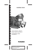
Installation guide


3
AHA-2840A/2842A Installation Guide
Part Number: 510590-00, Rev B
Print Spec Number: 492663-00
Current Date: 5/9/96 ECN Date: 6/3/96
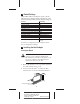
3 Remove the corresponding expansion board
access cover on the computer chassis.
4 Align the bus connector on the bottom of the host
adapter with the VL-Bus slot and carefully press
it down into the slot. Secure the host adapter
bracket to the computer chassis with the screw
from the removed expansion slot cover.
Note: Do not replace the chassis cover or
reconnect the power yet!
Setting Switches
If you need to change switch block settings, do it
now before you replace the chassis cover and run
SCSISelect. (See Section , Switch Block Settings.) In
most cases, you will never have to change the default
switch settings. The following are some situations in
which you should change the settings:
Controlling Floppy Drives
If your floppy drives are connected to another floppy
controller (e.g., the one on the motherboard), set sw5
to On to disable the AHA-2842A floppy controller.
If you want to use the floppy controller on the
AHA-2842A you must disable other floppy control-
lers in the computer; refer to the documentation for
your computer or floppy controller.
Using Multiple Host Adapters
The AHA-2840A/2842A port address must be differ-
ent from the port addresses of other expansion
boards and host adapters. If another board is using
the default AHA-2840A/2842A port address of
1C00h, change sw1-sw4 to a different port address
(see Section , Switch Block Settings).
Each installed host adapter must also have a differ-
ent BIOS address, which is set by sw6 and sw7. Or,
you can disable the AHA-2840A/2842A BIOS by set-
ting sw8 to On. (See the next section.)
Disabling the BIOS
CD-ROM drives, tape drives, and other nondisk
devices do not use the host adapter BIOS. Therefore,