User's Manual ICP Controllers of the GDT RS and RN Series 32-Bit / 64-Bit PCI Ultra2 SCSI and Ultra 160 SCSI RAID Controllers 1st Edition © Copyright 1998-2000 ICP vortex Computersysteme GmbH Konrad-Zuse-Str. 9 74172 Neckarsulm - Germany ICP vortex Corporation 4001 E. Broadway / B-20 Phoenix, AZ 85040, USA All Rights and Changes Reserved.
Contents - Overview Part I Chapter A Chapter B Chapter C General Information Hardware Installation Quick-Setup Part II Chapter D Chapter E Chapter F Chapter G Chapter H Chapter I Using Microsoft MS-DOS, Windows 95/98 Using Novell NetWare Using Windows NT/2000 Using LINUX Using SCO UNIX Using UnixWare Part III Chapter J Chapter K Chapter L The ICP RAID Console The ICP RAID Navigator Appendix
Limited Warranty ICP vortex Corporation ("ICP vortex") guarantees that this product is free from defects in material and workmanship. Subject to the conditions and limitations set forth below, ICP vortex will, at its own option, either repair or replace any part of this product which proves to be defective by reasons of improper workmanship or materials.
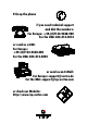
Pick up the phone if you need technical support and dial the numbers: For Europe: +49-(0)7132-9620-900 For the USA: 602-414-0414 or send us a FAX: For Europe: +49-(0)7132-9620-400 For the USA: 602-414-0444 or send us an E-Mail: For Europe: support@vortex.de For the USA: support@icp-vortex.com or check our Website: http://www.icp-vortex.
Important Note Using modern RAID Systems significantly increases data security and availability. Under no circumstances does it relieve you from a careful and daily backup on tape or a similar backup media. This is the only method to protect your valuable data against total loss (e.g., through fire or theft), accidental deletion, or any other destroying impacts.
FCC Compliance Statement Information for the User NOTE: This equipment has been tested and found to comply with the limits for a Class B digital device, pursuant to Part 15 of the FCC Rules. These limits are designed to provide reasonable protection against harmful interference in residential installations. This equipment generates, uses, and can radiate radio frequency energy, and if not installed and used in accordance with the instructions, may cause harmful interference to radio communications.
Table of Contents A. Introduction..................................................................................................................................................16 A.1 Product Identification .............................................................................................................................16 A.1.1 Key Features of the ICP Controllers of the GDT RS and RN Series...........................................................17 A.2 Copyrights, Patents .................
C. Quick-Setup .................................................................................................................................................54 C.1 What is the Aim of Quick-Setup ?.........................................................................................................54 C.2 What is the ICP Controller Firmware ? ......................................................................................................54 C.2.1 The Different RAID Levels........................
D.8 Installing Windows 98 ...........................................................................................................................80 E. Using Novell NetWare ...................................................................................................................................82 E.1 Transparency of Host Drives ....................................................................................................................82 E.2 Novell NetWare 3.10, 3.1, 3.12 and 3.20....
G.6 gdth driver parameters .........................................................................................................................100 G.7 Notes .................................................................................................................................................101 H. Using SCO UNIX V/386...............................................................................................................................104 H.1 Transparency of Host Drives............
J.4.3.1 Menu Advanced Setup: Configure Controller, Controller Settings................................................130 J.4.3.2 Menu Advanced Setup: Configure Controller, Firmware Update .................................................131 J.4.3.3 Menu Advanced Setup: Configure Controller, Intelligent Fault Bus.............................................131 J.4.3.4 Menu Advanced Setup: Conf. Controller, Non-Intelligent Enclosures...........................................131 J.4.3.
K.1 Introduction ........................................................................................................................................148 K.2 The ICP RAID Navigator "Controls".........................................................................................................149 K.2.1 The Toolbar...................................................................................................................................149 K.2.2 The Status Bar.................................
L.1 Technical Data of the ICP Controller........................................................................................................184 L.2 Boot Error Messages .............................................................................................................................184 L.3 Index ..................................................................................................................................................
Chapter A General Information
A. Introduction GDT RN Series: 64 Bit PCI hardware RAID Disk Array Controllers with up to 3 Wide/Ultra2 SCSI or up to 6 Ultra 160 SCSI channels GDT RS Series: 32 Bit PCI hardware RAID Disk Array Controllers with up to 3 Wide/Ultra2 SCSI channels In order to take full advantage of modern operating systems, high performance computer systems are needed. When assessing the performance of a computer system, the aspects speed and security of the mass-storage subsystem are gaining increasing importance.
GDT RN Series, 64-Bit PCI Bus (Controllers can be operated in a 32-Bit and 64-Bit PCI Bus) with Wide/Ultra2 SCSI channels ICP Controller Name GDT7118RN GDT7128RN GDT7518RN GDT7528RN GDT7538RN GDT7618RN GDT7628RN GDT7638RN Number of Wide/Ultra2 SCSI channels 1 2 1 2 3 1 2 3 One Wide/Ultra SCSI channel Yes Yes Yes Yes Yes Yes Yes Yes Clustering Support Optional Optional Optional Optional Optional Yes Yes Yes Supported RAID Levels 0/1 0/1 0/1/4/5/10 0/1/4/5/10 0/1/4/5/10 0/1/4/5/10 0/1/4/5/10 0/1/4/5/1
ROM-resident character-based configuration and monitoring utility ICP RAID Console . Express Setup option to easily setup Array Drives. Press "CTRL-G" to load ICPCON, long before the operating system is booted. ICPCON is also available as an executable program under the various supported operating systems. ICP RAID Navigator. GUI-style configuration and monitoring utility for Windows 95/98/NT/2000. ICPCON. Character oriented program for Windows 95/98/NT, NetWare, Linux, SCO UNIX, UnixWare.
A.2 Copyrights, Patents Parts of the ICP GDT RN and RS Series controllers are protected under international copyright laws and agreements. No part of the product or the manual, or parts of the manual may be reproduced in any form, physical, electronic, photographic, or otherwise, without the expressed written consent of ICP vortex Computersysteme GmbH. For this product a patent is registered at the Deutsches Patentamt in Munich with the official reference no. 4121974.
A.3 Software License Agreement Please read this Software License Agreement before opening the CD/disk packaging and before starting to use the programs. Each loading of a program covered by this license agreement, each transmission within any existing network to another computer, as well as each copy on a mass storage system, regardless of what kind (floppy disk, hard disk,CD, MO, etc.), represents a duplication of the program according to copyright regulations.
A.4 General Information The ICP Controller should be installed by an authorized ICP vortex distributor. Precondition for the safe installation is an anti-static work place (earthed mat on the table with wrist bands connected to an earth). ICP vortex does not take any responsibility for damage arising out of improper installation. This manual contains all the information available at the time it was written. Errors and/or incomplete information are possible.
A.5 Product Description A.5.1 Intel i960RS or i960RN I/O Processor The i960RS/RN I/O processors are members of a new RISC CPU generation which was specifically designed for I/O applications. This pure 64 Bit CPU on an ICP Controller can reach a performance of +100 MIPS and supervises all tasks of the SCSI devices, the RAID controlling and the communication with the PCI computer. In doing so, it significantly offloads the PCI computer, leaving it free to perform its original tasks. A.5.
troller. Thus, the host is significantly offloaded. In addition, this hardware-implemented solution guarantees the highest achievable security. The controller-BIOS provides a complete PCI compatible INT13 interface and expands the respective functions of the system BIOS. It also ensures that operating systems using the INT13 (i.e. MS-DOS, OS/2) can be booted directly from a SCSI device / RAID Array Drive connected to the ICP Controller.
ICP Firm w are / ICP BIO S / ICP Tools ICP Firm w are / IC P BIO S and rom -residente ICP RAID Console (-) character-oriented G rap hical User Interface M S-DO S / D R-DO S W indow s 9x W indow s NT/2000 NetWare, SCO UNIX SCO UnixWare LINU X, Solaris 7 W indow s 9x W indow s NT/2000 Setup & C onfigure Controller Physical D evices Logical Drives Array Drives Host Drives Setup & C onfigure Controller Physical D evices Logical Drives Array Drives Host Drives M onitor Controller Physical D
A.5.8 Operating System Driver Software Drivers for the following operating systems are available: Operating System MS-DOS 3.3 to 6.x Novell NetWare 3.x, 4.x, 5.x SCO UNIX System V/386 3.2v5.x SCO UnixWare 2.x and 7 Windows NT, 3.5x, 4.x Windows 2000 Windows 95/98 Solaris 7 Linux Driver included with the Controller Package Yes Yes Yes Yes Yes Yes Yes Yes Yes The following table shows how various devices are integrated by different operating systems.
M ode LED O N = LVD O FF = SE Term ination alw ays O N Feature Socket SE C hannel Term ination alw ays O FF 64-Bit PCI B us Connector Controller can also be operated in a 32-Bit PCI Bus Channel A Term ination via Soft-Sw itches (Default) Acoustical Alarm T=DM A S=Status S Term inator Pow er (Default: Jum per closed) SUM SE A DBPM Terminator U nbuffered PC100 DIM M 16, 32, 64, 128M B Standard and ECC Anode Cathode LED Connector SUM SE A SCSI Activity SE A T 26 GDT7118RN, GDT7518RN and GDT
Channel A TPB TPA Acoustical Alarm Channel B 64-Bit PCI Bus Connector Controller can also be operated in a 32-B it PC I Bus TPx = Term inator Power (Default: Jum pers closed) Feature Socket Term ination always O N Channel B Term ination via Soft-Switches (Default) Channel A T=DM A S=Status S SE Channel Anode Cathode M ode LED ON = LVD OFF = SE Unbuffered PC100 D IM M 16, 32, 64, 128M B Standard and EC C Term inator Pow er SE Channel (D efault: Jum per closed) TPSE Term ination always O F
TPC TPB TPA Acoustical Alarm 64-B it PC I Bus Connector Controller can also be operated in a 32-Bit PCI Bus TPx = Term inator Pow er (Default: Jum pers closed) Feature Socket Term ination alw ays ON Channel B Term ination via Soft-Switches (Default) Channel A T=DM A S=Status S TPSE SE Channel Anode Cathode M ode LED O N = LVD O FF = SE Unbuffered PC100 D IM M 16, 32, 64, 128M B Standard and EC C Term inator Pow er SE Channel (Default: Jum per closed) Channel C Term ination alw ays O FF
M ode LED O N = LVD O FF = SE S Term ination alw ays ON Term ination alw ays OFF Term inator Pow er (Default: Jum per closed) Term ination via Soft-Sw itches (Default) Acoustical Alarm T=DM A S=Status SCSI Activity T U nbuffered PC100 DIM M 16, 32, 64, 128M B Standard and ECC Anode Cathode LED Connector 29 GDT6118RS and GDT6518RS Overall View
Channel A TPB TPA Acoustical Alarm TPx = Term inator Power (Default: Jum pers closed) Term ination always ON Channel B Term ination via Soft-Switches (Default) Channel A T=DM A S=Status S M ode LED ON = LVD OFF = SE Term ination always O FF Unbuffered PC100 D IM M 16, 32, 64, 128M B Standard and EC C Anode Cathode SUM T SUM LED Connector A B A B SCSI Activity A B 30 GDT6128RS and GDT6528RS Overall View Channel B
Channel A TPC TPB TPA Acoustical Alarm TPx = Term inator Pow er (Default: Jum pers closed) Term ination alw ays ON Channel B Term ination via Soft-Switches (Default) Channel A T=DM A S=Status S M ode LED O N = LVD O FF = SE Channel C Term ination always O FF Unbuffered PC100 D IM M 16, 32, 64, 128M B Standard and EC C Anode Cathode SUM T SUM LED Connector A B C A B C SCSI Activity A B C 31 GDT6538RS Overall View Channel B
Channel A Channel B B Term ination always ON A Channel B Feature Socket M ode LEDs: ON = LVD / O FF = SE 64-Bit PCI B us Connector Controller can also be operated in a 32-Bit PCI Bus Channel A T=DM A S=Status Term ination via Soft-Switches (Default) Term inator Pow er; (Default: B oth Jum pers set) Acoustical Alarm B A ABTS Activity SCSI A, B TS LVDB AB LVDA B B A node C athode LED Connectors Term ination always OFF A Unbuffered PC100 DIM M 16, 32, 64, 128M B Standard and ECC SU
Channel A Channel A Acoustical Alarm SUM A B C D Anode Cathode C hannel B Feature Socket Channel C Channel D Add itio nal S ettings for Channel B A ctivity SCSI D C B Unbuffered PC100 DIM M 16, 32, 64, 128M B Standard and ECC Add itio nal S ettings for Channel B A Term ination alw ays O FF M ode LED ON = LVD O FF = SE (Jum pers should alw ays be set) Term ination alw ays O N Term ination Power O N Term ination via Soft-Sw itches (Default) Add itio nal S ettings for Channel B TS Term
Channel A Channel A Acoustical Alarm SUM A B C D E F Anode Cathode LED Konnektor C hannel B Feature Socket Channel C Channel D Add itio nal S ettings for Channel B A ctivity SCSI F E D C B Unbuffered PC100 DIM M 16, 32, 64, 128M B Standard and ECC C hannel F Channel E Additio nal S ettings for Channel B A Term ination alw ays OFF M ode LED O N = LVD O FF = SE (Jum pers should alw ays be set) Term ination alw ays ON Term ination Power O N Term ination via Soft-Switches (Default) A
Chapter B Hardware Installation
B. Hardware Installation B.1 Before Installation The ICP Controller is designed for minimum power consumption and maximum operational security. It therefore contains delicate electrical components (CMOS).
B.4 SCSI - Basics Whoever has been involved with the subject of SCSI will have noticed that the "Small Computer System Interface" is an extremely interesting technology, which has become widely accepted in comparison to other interface models and has constantly adapted to the needs of customers. This builds up confidence and (investment) security. Last but not least, SCSI has remained the de facto I/O interface for smaller to mid-sized mass storage systems.
explicitly designed for LVDS. Very often all GND wires are put together in the connector. These kinds of cables must not be used for LVDS. 80MB/sec. or 160MB/sec synchronous data transfer rates Up to 12 Meters cable length It is very important for you to observe the information and notes given in this section of the User’s Manual because it helps to ensure that the SCSI devices that are used in connection with the ICP Controllers are operated in a successful, long-lasting and trouble-free manner.
Avoid using SCSI cables with more connectors than actually needed. Never select a SCSI mode or operate a SCSI device with a cable that is not appropriate for this mode. The minimum distance between two connectors of a SCSI cable is 20 cm. Avoid cable stubs. If this is not possible, keep the stub length below 10 cm. “Star cabling” are not allowed. Keep the number of transitions from flat to round cables and vice versa as small as possible. It is usually best is to use flat or round cables, only.
Example for a SCSI Flat Ribbon Cable for 8 Bit SCSI Devices (narrow)
Example for a SCSI Flat Ribbon Cable for 16 Bit SCSI Devices (wide)
Example for a Wide/Ultra2 and Ultra 160 Flat Ribbon Cable (1.
B.4.2 SCSI Termination In order to ensure a flawless and interference-free signal transmission on the SCSI bus and to minimize the detrimental effects of external noise generators, both ends of the SCSI cable have to be terminated. The SCSI specification prescribes different termination methods for SE and LVDS SCSI bus systems. There are two alternative termination modes for Single-Ended SCSI bus systems: The passive termination and the active termination, also known as Alternative-2 termination.
The factory set SCSI ID of the ICP Controller SCSI channel is 7. Up to 15 SCSI devices can be connected to the Wide/Ultra2 and Ultra 160 SCSI channels Up to 15 SCSI devices can be connected to the Wide/Ultra SCSI channel. In reality this number is limited to max. 7. If it is intended to operate on this bus also Wide/Ultra2 or Ultra 160 disk drives, you must set the "SE" jumper on each Wide/Ultra2 disk drive. On IBM drives e.g., this jumper is called "SE Mode".
8846 Narrow-Wide Bracket 8849 Wide/Ultra2 and Ultra 160 SCSI Bracket Wide/Ultra2 and Ultra160 SCSI Bracket 8850 8951 LVDS/SE Terminator 8952 LVDS/SE Terminator for SE/LVDS Hard Disks with SCA Connector. 8953 External LVDS/SE Terminator SCSI Wonder 8954 External SCSI connector with an internal Connection of an external Nar68 pin connector (female) and an external row/Ultra SCSI subsystem with an 50 pin HD SCSI connector (female). internal Wide/Ultra channel. Not for LVDS operation.
SE/LVD Terminator for SE/LVD hard disks with SCA connector. B.4.5 Examples On the following pages, are some examples of correct SCSI cabling. First of all a few general tips: All ICP Controllers have a yellow LED for each Wide/Ultra2 and Ultra 160 SCSI channel. This LED indicates the current SCSI-Mode of the corresponding channel. If the LED is lit, the Wide/Ultra2 and Ultra 160 SCSI channel is operating in LVDS-Mode. If the LED is not lit, this channel is operating in SE-Mode only.
Several internal Wide/Ultra2 and Ultra 160 SCSI Hard Disks
Internal and external Wide/Ultra2 and Ultra 160 SCSI Hard Disks B.5 ICP Controller Installation Make sure that the ICP Controller is equipped with an appropriate unbuffered PC100DIMM (at least 16MB). It is not possible to operate the ICP Controller without a DIMM. Step 1 Switch off the PCI computer system and remove all cables (first of all the power supply).
Step 4 Push the ICP Controller firmly into the correct PCI bus-master slot. Make sure that the controller fits tightly into it, and that the external connectors stick out of the computer case. Now, fix the ICP Controller by tightening the screw of its bracket. Step 5 To connect the external SCSI enclosures use suitable round cables (see ICP vortex SCSI Accessories – section B.4.4). Make sure that cables are fastened with the corresponding connectors.
The electronic loudspeaker of the ICP Controller gives forth a series of 4 signals with a pause between the first two). The other green LED "T" may flicker sometimes (it always lights up during BUS-Master DMA transfers; the brighter it lights, the more DMAs). The yellow LEDs indicate accesses to the devices. They also may flicker occasionally as the ICP Controller scans the I/O channels for existing devices. The ICP boot message appears.
GDT7518RN -- HWL0 -- 32 MB SDRAM / ECC - 2048kB Flash-RAM GDT7518RN -- HWL0 stands for the type of ICP Controller found by the GDT BIOS. HWL means Hardware level. 32 MB SDRAM /ECC indicates that the installed DIMM is a 32MB ECC SDRAM module. Depending on the size of the installed PC100 DIMM the following messages are possible (xx = 16, 32, 64 and 128): xx MB SDRAM/ECC xx MB ECC-SDRAM-Module 2048kB indicates the size of the installed Flash-RAM.
Chapter C Quick-Setup
C. Quick-Setup C.1 What is the Aim of Quick-Setup ? In the previous chapter we installed the ICP Controller in a PCI computer and connected the SCSI devices. Now these devices must be prepared in order to run with your operating system. This Quick-Setup chapter should help you to get started quickly. Quick-Setup shows three examples: Example 1 Example 2 Example 3 Installing a single hard disk. Installing a Mirroring Array Drive (RAID 1), consisting of 2 hard disks.
Cluster RAIDYNE® (installed on the GDT76x8RN or GDT76x3RN controllers). In addition to disk chaining, RAID 0 and RAID 1, RAIDYNE® allows you to install and control Array Drives of the types RAID 4 (data striping with dedicated parity drive), RAID 5 (data striping with distributed parity) and RAID10 (a combination between RAID 0 and 1). Includes also functions to support Microsoft Cluster Server.
C.2.1 The Different RAID Levels RAID 0 - Data Striping According to the adjusted stripe size (e.g., 128 KB) and the number of hard disks, the data blocks are split into stripes. Each stripe is stored on a separate hard disk. Especially with sequential read and write operations, we can observe a significant improvement of the data throughput. RAID 0 includes no redundancy at all, i.e., when one hard disk fails, all data is lost.
RAID 4 - Data Striping With a Dedicated Parity Drive RAID 4 works in the same way as RAID 0. The data are striped amongst the hard disks. Additionally, the controller calculates redundancy data (parity information) which are stored on a separate hard disk (P1, P2, ...). Even when one hard disk fails, all data are still fully available. The missing data is recalculated from the data still available and the parity information.
RAID 10 - Combination of RAID 1 and RAID 0 The idea behind RAID 10 is simply based on the combination of RAID 0 (Performance) and RAID 1 (Data Security). Unlike RAID 4 and RAID 5, there is no need to calculate parity information. RAID 10 disk arrays offer good performance and data security. As in RAID 0, optimum performance is achieved in highly sequential load situations. Identical to RAID 1, 50% of the installed capacity is lost for redundancy.
C.2.2 Levels of Hierarchy Within the ICP Firmware The ICP firmware is based on four fundamental levels of hierarchy. Each level has its "own drives" ( = components). The basic rule is: To build up a “drive“ on a given level of hierarchy, the “drives“ of the next lower level of hierarchy are used as components. Level 1: Physical Drives = hard disks, removable hard disks, some MO drives are located on the lowest level. They are the basic components of all "drive constructions" you can set up.
Generally, each installation procedure passes through these 4 menus, starting with level 1. Therefore: First initialize the Physical Drives. Then configure the Logical Drives. Then configure the Array Drives (e.g. Array Drives with RAID 0, 1, 4, 5 and 10). Finally, configure the Host Drives. C.2.3 Using CD-ROMs, DATs, Tapes, etc. A SCSI device that is not a SCSI hard disk or a removable hard disk, or that does not behave like one, is called a Not Direct Access Device.
Select the menu option Configure Host Drives with ENTER. The list of available Host Drives contains already an entry. There is a RAID 5 Host Drive. After selecting Create new Host Drive ICPCON displays a list of “free” hard disks. These are all the drives which do not belong to a Logical or Hosr Drive and can be used for new Host Drives. Select a hard disk with the SPACE bar (it becomes marked with an "*") and press ENTER.
The new Host Drive is assigned a Host Drive Name (here PD_A000) which helps for better identification, especially in configurations with many different Host Drives. The name can be easily changed. C.4 Example 2 - Installing a Mirroring Array - RAID 1 Press the key combination when the ICP BIOS message comes up (shortly after switching on the computer) and load ICPCON from the Flash-RAM of the ICP Controller. In this case no operating system is required.
Move the selection bar with the cursor keys from on entry to another (pressing the SPACE bar again undoes your choice). The Choose Type menu offers four different Host Drive Types. For this example we select RAID 1 and press ENTER. ICPCON displays a warning that all data will be destroyed after confirmation. ICPCON allows you to limit the hard disk size for this Host Drive.
Select the menu option Configure Host Drives with ENTER. The list of available Host Drives contains already an entry. There is a RAID 5 Host Drive. After selecting Create new Host Drive ICPCON displays a list of “free” hard disks. These are all the drives which do not belong to a Logical or Host Drive and can be used for new Host Drives. Select four hard disks with the SPACE bar (these hard disks become marked with an "*") and press ENTER.
ICPCON allows you to limit the hard disk size for this Host Drive. This becomes interesting when you configure disk arrays and you want to make sure that future drives you want to bring into the disk array (for replacement or online capacity reasons) fit. It would be bad luck if the new drive only had 8681 MB. ICPCON couldn't accept it. To avoid this occurring, you could limit the capacity of each drive to 8000 MB. Any new 9 GB drive must have at least this capacity.
C.6.2 Which Level of Redundancy is Needed ? To come straight to the point, RAID 0 (data striping) does not imply any redundancy at all (the R in front of the AID is rather misleading). On the other hand, a RAID 0 disk array is pretty fast, since no parity information is required. With RAID 1 (disk mirroring), the data is 100% redundant because it is mirrored. This is definitely the highest level of redundancy, but the most expensive one, too. An interesting combination of RAID levels 0 and 1 is RAID 10.
C.7 States of a RAIDYNE® Disk Array An Array Drive under the RAIDYNE® operating system can assume seven different operational modes: Idle, Ready, Fail, Build, Rebuild, Expand and Error. C.7.1 "Idle" State This state is characterized by the fact that the redundant information of the disk array has never been entirely created. The disk array is in this state after its first configuration and until you quit ICPCON.
(*) Replacement either manually, or through hot fix method.
C.8 Methods for the Replacement of a Disk Drive The ICP Controller and the ICP Firmware offer a variety of possibilities to replace a defective disk drive. If and when to use them depends on the physical environment of your server. With some servers the disk drives are just mounted into the server enclosure, they are not removable. With other servers there is a backplane which is intelligent (e.g., with SAF-TE) and which hosts a number of disk drives with the SCA connector (Single Connector Attachment).
Chapter D Using MS-DOS
D. Using Microsoft MS-DOS After having explained the installation of the ICP Controller and the Host Drives in chapters B and C, we now explain how to install the operating system MS-DOS. By using some examples, we shall demonstrate how to use a CDROM drive (standing for any other Not Direct Access Device) under MS-DOS. In addition, we will give you further information on how to install Windows 95 and Windows 98. The required ICP disks for DOS and Windows 95/98 can be created from the ICP System CDROM.
GDTX000.EXE can be loaded in the UMA. GDTX000.EXE is needed for an optimal use of Windows 3.x. The ICP Controller unfolds its full capacity under MS-DOS or Windows 3.x only when GDTX000.EXE is installed. In order to load ICPCON under MS-DOS from disk, you need GDTX000.EXE. In the CONFIG.SYS file, GDTX000.EXE must be loaded before GDTASPI.EXE. Below is an example of a CONFIG.SYS file which is essential for the MS-DOS configuration device=c:\windows\himem.sys device=gdtx000.
thank Mr. Georg Schnurer and the c’t magazine for allowing us to use this very helpful utility on our system disks. Example 1: The Microsoft EMM386.EXE Manager is used. The ICP driver GDTX000.EXE has not been loaded from the CONFIG.SYS: DEVICE=EMM386.EXE X=D000-D3FF X=E000-E1FF Example 2: The Microsoft EMM386.EXE Manager is used. The ICP driver GDTX000.EXE has been loaded from the CONFIG.SYS: DEVICE=EMM386.EXE X=D000-D3FF (Note: You may have to add the path for "EMM386.EXE".
D.5.1 Example: Using the ASW Software for the CDROM The important lines in both files are printed bold. CONFIG.SYS device=c:\windows\himem.sys device=gdtx000.exe files=30 buffers=30 stacks=9,256 dos=high,umb shell=\COMMAND.COM /E:512 /P device=\dos\setver.exe device=\gdt\gdtaspi.exe device=\aspi\aspicd.sys /D:CDROM lastdrive=h AUTOEXEC.BAT path=c:\;c:\dos;c:\gdt;c:\aspi; prompt $P -$G doskey c:\aspi\mscdex /D:CDROM The GDTX000.EXE driver is loaded from the first line following the HIMEM.
buffers=30 stacks=9,256 dos=high,umb shell=\COMMAND.COM /E:512 /P device=\dos\setver.exe device=\gdt\gdtaspi.exe device=c:\corel\cuni_asp.sys /ID:6 /HAN:0 /N:1 /D:MSCD000 lastdrive=h AUTOEXEC.BAT path=c:\;c:\dos;c:\gdt;c:\aspi; c:\corel\corelcdx /M:8 /D:MSCD000 The first line following the HIMEM.SYS command of the CONFIG.SYS file loads the GDTX000.EXE. The next line loads the ICP ASPI Manager GDTASPI.EXE. Next, the corel ASPI Module for the CDROM drive is loaded.
Example: We assume that there is only one ICP Controller in the system. Two direct access devices, the removable hard disk connected to channel A, ID 2, and the hard disk connected to channel B, ID 4, have to be reserved for the ASPI manager. The corresponding entry in the CONFIG.SYS is: DEVICE=GDTASPI.EXE /R:H0I2:H1I4 Important note: SCSI devices reserved for the ASPI manager must not have been initialized with ICPCON. Neither must they pertain to an ICP Logical or Host Drive.
Note: Drives run with corelSCSI and the UNI_ASP.SYS driver are neither compatible with drives run with ICPCON and the ICP cache nor with those run with the above mentioned ASPIDISK.SYS driver. D.7 Installing Windows 95 This guide will take you through the process to install the files necessary to allow the controller to operate under Windows 95.
1. Find the ICPCON.EXE file in the DRIVERS\WIN95 directory on the ICP System CD. 2. Copy ICPCON.EXE to your Host Drive. Start the ICPCON program. 3. Press ENTER to select the Controller. Press ENTER to select the Protocol. 4. Press ENTER to select the Controller installed. 5. Highlight View/Change Settings and press ENTER. 6. Highlight Cache Settings and press ENTER. 7. Highlight Delayed Write. Use the space bar to toggle setting to ON. 8. Press ENTER two times. Delayed Write is now enabled. 9.
2. Run WIN95.EXE to get the update files. 3. Format a 3.5” HD disk (1.44MB). Copy all Windows 95 files to this disk. 4. In Windows 95 double click on My Computer icon. Double click Control Panel. 5. Double click System icon. Click Device Manager tab. 6. Double click SCSI controller icon. Double click the ICP Controller shown. 7. Click Driver tab. Click Change Driver. 8. Click Have Disk. Insert the Windows 95 driver disk created in step 3. 9.
Chapter E Using NetWare
E. Using Novell NetWare After having explained in chapters B and C the installation of the ICP Controller and the Host Drives, we would now like to give you some hints and pieces of advice on how to install Novell's operating system Novell NetWare. We shall mainly focus on NetWare 3.x, NetWare 4.x and NetWare 5. For successful installation, it is essential to study the NetWare system manuals thoroughly. The information given in this chapter refers to the loading of the ICP NetWare driver(s) only.
GDTRP400.DSK ASPITRAN.DSK CTRLTRAN.DSK for NetWare 4.x ASPI manager Module for ICPCON (Note: More information about the ICPCON diagnosis tool may be found in a separate chapter in this manual.) if you wish to install NetWare 4.x from a CDROM, you first have to set up the CDROM drive under MS-DOS, following the instructions given in chapter D, section D.6. Then install NetWare following the instructions in the NetWare documentation.
Change all command lines in STARTUP.NCF and in AUTOEXEC.NCF from DSK to HAM. If CTRLTRAN.DSK is loaded directly, this command line must also be changed (CTRLTRAN.HAM). If the DSK driver is replaced by the HAM driver, the slot number parameter has to be changed as well. ASPITRAN.DSK is not required any more and can be deleted. NWASPI.CMD is used instead (part of NWPA_411.EXE). This ASPI driver has to be loaded if you want to use ASPI devices. New Installation of NetWare 4.
Continue with the server installation. 'Down' and 'Exit' the server at the end of the installation. Copy all files except NWPA_411.EXE from the temporary directory to the start-directory of the server. The temporary directory can be deleted afterwards. New installation of NetWare 5.x with ICP HAM driver In order to install NetWare 5.x, we recommend to follow the standard installation procedure of the NetWare 5.x server. E.5 Tips and Tricks E.5.
E.5.3 Installing NetWare 4.1 - Wrong Drive Name The following problem often occurs when installing NetWare 4.1 server: While copying the module cdrom.nlm the system hangs - forever. This problem only occurs when the CDROM drive's name under MS-DOS is 'cdrom', i.e., the config.sys/autoexec.bat contains the following files: DEVICE=aspicd.sys /D:cdrom and mscdex /D:cdrom To avoid this problem, simply change the CDROM's name in DOS to another name, i.e., use '/D:scsicd' instead of '/D:cdrom'. E.5.
E.5.6 Last Status Information All ICP Controllers temporarily store the status information from all hard disks which are connected. This information can be very useful when searching for possible causes of disk failures or interferences. The last status information consists of a hexadecimal, 8 digit number and can be displayed via the ICPCON or can be saved in a SAVE INFORMATION ASCII file. The information is temporarily available in the ICP Controller's RAM.
Chapter F Using Windows NT or Windows 2000
F. Using Microsoft Windows NT or Windows 2000 After having explained the installation of the ICP Controller and the host drives in chapters B and C, we now explain how to install the operating systems Microsoft Windows NT and Windows 2000. For a successful installation, we recommend that you take a close look at the manuals which came with your Windows NT/2000 package. The required ICP disks can be created from the ICP System CDROM. F.
In order to avoid this problem and prevent the risk of data corruption, the Delayed Write function of the ICP cache must be disabled during the complete installation. To do so, use the ICPCON program, choose Advanced Setup, Configure Controller, Controller Settings and switch the Delayed Write function OFF. After having completed the Windows NT installation, switch the Delayed Write function ON again. Step 3 – Check the Master Boot Record.
Step 4 – Enabling the CDROM Boot for a SCSI CDROM on the ICP Controller (Note: This step is not necessary if you boot the Windows NT CD from a CDROM which is not controlled by the ICP Controller). Load ICPCON and press F4 for the Advanced Setup Mode. Select the Configure Controller menu and enable the CDROM-Boot. F.2.2 The Installation First of all, make sure that you have verified or carried out all steps described in section F.2.1. F.2.2.
At the next system boot the ICP driver is loaded and the existing Host Drives are ready to be partitioned under Windows NT. F.2.3 Using the Hot Plug Function with RAID Host Drives In order to be able to use the Hot Plug function under Windows NT, you my either use ICP RAID Console or ICP RAID Navigator. F.2.4 Installation of a new GDTX.SYS Driver Version If it should become necessary to install a new version of the GDTX.SYS driver, the procedure is as follows: a) Double click the My Computer icon.
To do so, follow these instructions: 1. Load the Registry Editor regedt32.exe in \...\system32 2. Select the window HKEY_LOCAL_MACHINE on Local Machine 3. Choose the Key gdtx in the directory SYSTEM\CurrentControlSet\Services\ . 4. Enter by means of Edit, function Add Key, the name Parameters . Select Parameters . 5. Enter by means of Edit, function Add Key, the name Device . Select Device . 6. Enter by means of Edit, function Add Value, the name DriverParameter . 7. Use data type REG_SZ.
Step 1 - Create an ICP Windows 2000 driver disk. You need a 3.5" HD formatted floppy disk. Create from the ICP System CDROM the ICP Windows 2000 driver disk (you can copy file by file or write an image). If you copy file by file do not use the Explorer, because it may not copy all files from the ICP System CDROM. Note: You cannot use the ICP Windows NT driver disk for installing Windows 2000.
Chapter G Using LINUX
G. Using LINUX After having explained the installation of the ICP Controller and the host drives in chapters B and C, we now explain how to install the operating system LINUX. For a successful installation, we recommend that you take a close look at the manuals which came with your LINUX distribution package. We have tested LINUX from: Caldera, Debian, DLD, LST, RedHat and S.u.S.E. . If you require an ICP Linux disk, this can be created from the ICP System CDROM. G.
b) Carry out the patch, e.g. for Linux 2.0.36: cd /usr/src/linux zcat gdtp2036.gz | patch -p1 2>log_file Thereafter check the file log_file for possible errors c) Configure the Kernel / Enter the ICP Controller with: cd /usr/src/linux make config d) Check dependencies / Compile Kernel: see LINUX manual (e.g. make dep && make zlilo) e) Reboot system Update of a driver patch: a) Copy the new patch to /usr/src/linux b) Remove old patch with zcat old_patch.
G.6 gdth driver parameters Driver versions older than 1.05 do not support driver parameters. From driver version 1.05 to 1.07 it is necessary to add driver parameters directly in /usr/src/linux/drivers/scsi/gdth.c . From version 1.10 on you may use for the parameters the LILO boot prompt (gdth=...") or in /etc/lilo.conf the append command (append = "gdth=..."). Reservation of SCSI devices: The reservation of SCSI devices becomes necessary if you wish that so-called 'Direct Access Devices' (e.g.
Further driver parameters: irq1,irq2, etc. disable:Y disable:N reserve_mode:0 reserve_mode:1 reserve_mode:2 reserve_list:h,b,t,l,h,b,t,l, reverse_scan:Y reverse_scan:N max_ids:x rescan:Y rescan:N Only for ICP EISA Controllers with disabled BIOS (irq1, irq2, etc.
Chapter H Using SCO UNIX
H. Using SCO UNIX V/386 After having explained in chapters B and C the installation of the ICP Controller as well as that of the Host Drives, we would now like to give you a few hints regarding the installation of the operating systems SCO UNIX V/386 3.2v4.x, 3.2v5.x (Open Server) For a successful installation, it is essential to read the SCO system manuals thoroughly. The required ICP disks can be created from the ICP System CDROM. H.
is displayed, do not press ENTER immediately, but type in link ENTER. The system will then prompt you for the name of the BTLD driver. Now type in gdth. It may be necessary to type in the complete boot string. In this case, you have to add the following command: link=gdth btld=fd(xx) where xx is the "Minor Device Number" of the corresponding device file.
Therefore, the first Host Drive has target-ID 0 / LUN 0 and the second target-ID 0 / LUN 1.
SCSI-ID of Not Direct Access Devices 2 3 4 5 6 Used ICP SCSI channel A A A A A UNIX Target ID 2 3 4 5 6 UNIX LUN 0 0 0 0 0 2 3 4 5 6 B B B B B 2 3 4 5 6 4 4 4 4 4 Having to determine the Target ID and LUN in such a complicated manner might seem rather awkward. However, it is necessary to do so because the ICP Controllers have more than one SCSI channel, whereas UNIX can only manage host adapters with one SCSI channel. Therefore, the ICP UNIX driver has to make the appropriate transformations.
H.4 Instructions on mkdev (ADM) for 3.2v5.x (Open Server) Whenever the program mkdev hd (ADM) is started, you will be asked for the coordinates of the device you wish to install. The driver does not automatically display all devices connected, so after the installation you will find a tool named GDTSCAN in the directory '/etc'. The scanning can take up to several seconds, especially when there is more than one controller in the system.
Result: HA 0 Bus 0 Target-ID 0 LUN 0 0 0 1 1 1 1 0 1 0 0 0 0 2 3 0 1 2 3 0 0 0 0 0 0 Device 1st hard disk, Host Drive no. 0 (boot drive) Streamer CD-ROM hard disk, Host Drive no. 0 hard disk, Host Drive no. 1 DAT hard disk, Host Drive no.2 Important Note: ‘Not Direct Access Devices’ must not be connected to Bus 0, Target-ID 0, LUN 0. This is reserved for the boot device under SCO Unix 3.2V5.0 H.5 Further Information From version 4.x of SCO UNIX V/386 3.
Chapter I Using UnixWare
I. Using UnixWare After having exposed the installation of the ICP Controller as well as that of the Host Drives in chapters B and C, we would now like to give you some hints and pieces of advice on how to install the operating system UnixWare version 2.x and UnixWare 7. The required ICP disk can be created from the ICP System CDROM. I.1 Transparency of Host Drives The structure of the Host Drives, which have been installed with ICPCON (in chapter C), is not known to UNIX. I.e.
I.4 ICP Controller as an additional Controller We distinguish two cases. a.) No ICP Controller has been configured for UnixWare yet. In this case, the ICP driver must be installed from the UnixWare BTLD-Disk by means of the UnixWare desktop and the options "System Setup", "Application Setup". Alternatively, this procedure can be carried out from the UnixWare shell: "pkgadd -d /dev/dsk/f0t" (ICP driver disk in drive 0). b.) An ICP Controller has already been configured for UnixWare.
Result: HA 0 Bus 0 Target-ID 0 LUN 0 0 0 1 1 1 1 0 1 0 0 0 0 2 3 0 1 2 3 0 0 0 0 0 0 Device 1st hard disk, Host Drive no. 0 (boot drive) Streamer CD-ROM hard disk, Host Drive no. 0 hard disk, Host Drive no. 1 DAT hard disk, Host Drive no.2 I.6 Further Information During the installation of the ICP driver, additional tools are copied into the /etc direc- tory.
Chapter J ICP RAID Console ICPCON
J. The Program ICPCON ICP RAID Console (ICPCON) is an extremely helpful and flexible setup and diagnosis tool for the configuration, monitoring, maintenance and tuning of mass storage subsystems which are based on one or more ICP Controllers. Different to the ICP RAID Navigator (a GUI-style application for Windows 9x/NT/2000), ICPCON's user interface is characteroriented and available for all operating systems.
Loading ICPCON on a workstation. In this case, too, the ICP NetWare driver and the autoloading module CTRLTRAN must have been previously loaded on the fileserver console. In addition, the module CTRLIPX.NLM has to be loaded. This module searches for a file named CTRLIPX.CFG. This file must be located in the same directory as CTRLIPX.NLM. The system administrator has to set up a user group named ICP_OPERATOR.
These two lines can also be inserted in the .profile file and will then be automatically processed during each login. The ICPCON program itself is copied during the SCO UNIX installation into the /etc directory. ICPCON is loaded by entering: icpcon ENTER J.1.6 Loading ICPCON Under LINUX The ICP System CDROM includes two archives: Icpcon.tgz icpcona.
Type of Host Drive Disk Chain RAID 1 RAID 0 RAID 4 RAID 5 RAID 10 Description of Host Drive 1:1 assignment: Host Drive to hard disk (sometimes also called JBOD) Concatenation of several hard disks Mirroring Data Striping Data Striping with parity drive Data Striping with striped parity Combined RAID 0 and 1 Minimum number of hard disks 1 2 2 2 3 3 4 After loading ICPCON, the following screen appears (by pressing F10 you may toggle between black and white display or colored display). J.2.
After selecting „Sockets“ and „TCP/IP“ you may enter the IP address of the server (if you would have chosen „SPX/IPX“ ICPCON would scan the network for suitable servers, which have SPX/IPX protocol). After that you may enter your user name and password. J.2.2 Select Controller After this login procedure ICPCON delivers a list of ICP RAID Controllers which are installed in this server (in this example one GDT7563RN).
„Save Information“ creates a complete protocol file of the current RAID subsystem including all settings of the ICP Controller and the drives. This file can be used for documentary reasons or for remote diagnosis. „Configure Array Drives“ allows you to configure or create Array Drives. With „Configure Host Drives“ you can either configure already existing Host Drives, or create new ones. I.e., you can create under normal operation new Host Drives without shutting down the computer.
capacity (1MB = 1024KB). The figures shown at TOTAL represent the overall performance of the Host Drives as a whole. With the ← and → keys you may change the scale of the graphical KB/s indication. With the ↑ and ↓ keys you can scroll the screen to see further Drives (if available). After selecting the menu option „Cache Statistics“ you can view the utilization of the ICP Controller’s Caches, separated in the Read Cache and the Write Cache.
the SCSI channel the SCSI-ID the vendor and type Retries/Reassigns, Grown Defects and the Last Status (1) The Retries counter is incremented by one unit whenever the ICP Controller retries to access a hard disk.
At the end of this protocol is a chronological listing of boot messages and other events stored in the Flash-RAM of the ICP Controller. If the buffer is full, the oldest events are deleted first. In the menu „Configure Controller“ the logging buffer can be cleared with „Clear Log Buffer“. The logging list is a good source to analyze complex events and problems. J.4 The Menu Express/Advanced Setup J.4.
After selecting Configure Host Drives, ICPCON displays a list of already existing Host Drives. With a new system this list will show no entries. In this example there is already one Host Drive available. It’s name is ”RAID 5“ and it is an RAID 5 Array Drive (with approx. 17GB capacity). The status is “ready”. I.e., this Host drive is fully available and redundant.
"Rebuild" State The disk array will assume this state after the automatic activation of a Hot Fix drive or after a manual replacement carried out with ICPCON. The data and the redundant information are reconstructed and stored to the new drive. "Expand" State If the capacity or RAID level of an existing disk array is changed, the disk array changes its state into expand. As soon as the expansion or migration is completed, the state changes back to ready.
Finish the selection by pressing ENTER. ICPCON displays a security message pointing out that all existing data on the selected hard disks will be destroyed after confirming with Yes. After pressing “Y” the user may limit the capacity per hard disk which will be used for the Host Drive. This can be very helpful for the procurement of future spare hard disks. After that ICPCON automatically creates and configures thew new Host Drive and adds it to the list.
Drive list, which means that the operating system is booted from the Host Drive having the lowest number. For reasons of flexibility, a Host Drive's position in the list can be changed. However, the position of the Host Drive from which the operating system is booted and the position of the Host Drive from which ICPCON (disk version) was started (both can be the same), cannot be changed.
In this example there is one Array Drive in the FAIL state. I.e., the Array Drive is still operating but longer redundant. After pressing any key, ICPCON displays a list of Array Drives which are candidates for this online automatic repair. Note: Array Drives which have the „ERROR“ state are very critical and have lost 2 or even more drives. These Array Drives cannot not be repaired with this function. In such critical cases the data integrity can longer be maintained.
The „ERROR“ state of an Array Drive is very critical. There are several procedures in the ICP Controller’s firmware to handle such cases an bring back the Array Drive in operation without loosing data. The most suitable procedure for the specific case, should be elaborated with your system administrator or our technical support. (Note: ICP vortex offers 2-day RAID Workshops in our training center, which also focus on the resolution of such problems. J.4.3 Menu Advanced Setup: Configure Controller J.4.
Display Supported BIOS Drives CD-ROM Boot Memory Test Chn.
In this example one subsystem is already defined. Naturally, the hard disks with their disk shuttles could be also directly mounted in the server enclosure. The term “Enclosure” in these cases is more a definition set, which includes all hard disks which should be auto hot pluggable. The following example shows the slots of the enclosure which have been assigned with hard disks. To fill an empty slot, press ENTER and select the desired hard disk.
With the non-intelligent subsystems we highly recommend you to use only best quality components (disk shuttles, cables, terminators, etc.). J.4.3.5 Menu Advanced Setup: Configure Controller, Advanced Settings Within Advanced Settings there are three settings which control the configuration and address behavior of the ICP Controller’s BIOS and DPMEM. Normally, there is nothing to change here.
Read/Write; RO for Read Only). The IO-Processors and SAF-TE-Processors (in our example channel B ID 8: SDR, Inc. GEM312 REV001) to not have attributes. The next column lists the capacity of the hard disk in MB (1MB = 1024KB; 1GB=1024MB). The last column gives information on the assignment of this Physical Device to a Logical/Array/Host Drive.
J.4.4.1 Menu Advanced Setup: Configure Phys. Devs., SCSI Parameter /Initialize This option can destroy all data on the hard disk. If a hard disk is not yet initialized, you have to initialize it first. ICPCON copies ICP specific configuration blocks on the hard disk, a primary block and a mirrored secondary block. The possible settings are different if you select a SCSI hard disk or a Fibre Channel hard disk. With a FCAL hard disk there are only a few settings which are relevant.
If you leave this configuration form with and you have made changes, ICPCON displays a security request. The warning of the destruction of all data implies different evaluations, depending on the device's current state and the options you selected: First Initialization of the Device. In this case, the warning must be taken seriously. If the drive was previously connected to a different controller (e.g. NCR etc.) and still contains important data, this data will be lost now.
J.4.4.6 Menu Advanced Setup: Configure Phys. Devs., Lock/Unlock Disk This option is only high-lighted when you have selected a removable hard disk (e.g., Syquest, Iomega). Before you can initialize a cartridge you have to lock it. Before removing it you have to unlock it. J.4.4.7 Menu Advanced Setup: Configure Phys. Devs., Enclosure Status After selecting this option you can either view the Enclosure Status or view/configure the enclosure slots.
ICP Disk Array Controller SCSI Channel Hot Plug Control SEP Hard Disk FAN Temperature Power Supply N FA Power Supply Status LEDs Door Lock
J.4.5 Menu Advanced Setup: Configure Logical Drives Logical Drives (hierarchy level 2) are installed in this main menu option. Selecting Configure Logical Drives leads you to the screen shown next. The F4 key gives you a list of all the hard disks this Logical Drive consists of. If it is a Logical Drive of the type Disk, it only consists of one single hard disk. If a Logical Drive consists of more hard disks, it is of the type Chain (concatenation of several hard disks).
If you confirm with , ICPCON allows you to limit the size of the Logical Drive. This becomes interesting when you configure later on an Array Drive with several identical Logical Drives and you want to make sure that you get appropriate spare hard disks in the future. It would be bad luck if the new hard disk would have 17508MB, only. It simply wouldn't fit into the Array Drive. If you limit the capacity to e.g.
J.4.6.1 Menu Advanced Setup: Configure Array Drives, Change Drive Name This command allows you to change the name of an Array Drive. The name serves to identify an Array Drive in ICPCON or ICP RAID Navigator. This can be very helpful for configurations where several Host Drives of various types are operated by a single controller. J.4.6.
J.4.6.6 Menu Advanced Setup: Configure Array Drives, Remove Array Drive This command allows you to remove an existing Array Drive. All the data of the Array Drive will be lost ! Before you confirm the security request with , you should be sure about this choice.
Obviously, no other hard disk may fail until all data has entirely been reconstructed on the Hot Fix drive, because up to that moment, the system is operating without redundancy. Notes: In some literature, Hot Fix drives are also called Hot-Spare drives. You can add or remove Hot Fix drives also with the ICP RAID Navigator. J.4.6.8 Menu Advanced Setup: Configure Array Drives, Remove Hot Fix Drive This option allows you to remove a Hot Fix Drive from an existing Array Drive.
J.4.6.13 Menu Advanced Setup: Configure Array Drives, Create new Array Drive After pressing ENTER, ICPCON lists all free Logical Drives, which are free (not yet part of Array / Host Drives). The selection bar can be moved with the cursor up/down keys and the Logical Drives can be selected/deselected with the SPACE bar. The "M" means Master. For a striping array (RAID 0, 4, 5, 10), this is the first Logical Drive in the array.
The Array Drive has entered the build state, i.e., the parity information is currently generated. After completion of the build process, the Array Drive's state is ready, i.e., fault tolerant. Notes on the Configuration of RAID 0, 1, 4, 5 and 10 Arrays Drives (1) Use preferably Logical Drives of the type disk to build an Array Drive. Of course, RAID Array Drives can be configured with Logical Drives of the type chain, too, but the aspects of security should be taken into consideration as well.
J.4.7.1 Menu Advanced Setup: Configure Host Drives, Change Drive Name This command allows you to change the name of a Host Drive. The name serves to identify a Host Drive within ICPCON and ICP RAID Navigator. J.4.7.2 Menu Advanced Setup: Configure Host Drives, Swap Host Drives When the PCI computer is switched on, the Host Drives are initialized in the order of the Host Drive list, which means that the operating system is booted from the Host Drive having the lowest number.
Chapter K ICP RAID Navigator
K. ICP RAID Navigator K.1 Introduction The ICP RAID Navigator (ICPRNAV) is a powerful tool for setting up, monitoring and maintaining mass storage subsystems based on ICP Controllers. Different to ICP RAID Console the ICP RAID Navigator is a pure GUI-style application, designed for the operation under Windows 95, 98, NT and Windows 2000. The main features are: Setup of hard disks controlled by the ICP Controller Setup and initialize Physical Drives, change the SCSI parameters and cache settings.
K.2 The ICP RAID Navigator "Controls" K.2.1 The Toolbar The toolbar can be made visible or hidden by selecting "Toolbar" from the "View" menu: By clicking on the different buttons you can open and close the windows of the corresponding programs of the ICP RAID Navigator: The toolbar can be moved away from the top of the RAID Navigator window and is then shown in a small extra window.
K.2.4 "Help" Menu Commands The Help menu offers the following commands to provide you with online help: K.2.5 "File" Menu Commands Here you can end your ICP RAID Navigator session. Shortcuts: Press Alt+F4 or click to close the window. K.2.6 "View" Menu Commands Use the items in this menu to open or close the windows of the main components of the ICP RAID Navigator or change the appearance of the main window.
K.2.7 The "Chart" Menu The chart menu appears when you open the statistics window. Here you can add and remove data sources from the chart and configure the chart. K.2.8 The "Configuration" Menu Commands This menu appears if you have selected the Physical Configuration window or the Logical Configuration window. Here you can set the refresh rate for the Physical or the Logical Configuration windows.
K.3 Select Controller This window is used to select an ICP Controller for all further actions within the ICP RAID Navigator. In a first step you should select the desired protocol (Windows NT/95/98, Sockets, IBM NetBIOS) for the communication between the ICP RAID Navigator and the system which is equipped with the ICP Controller by double clicking on the protocol icon on the very left side of the window.
K.4.1 Controllers Icon Description double click opens... Controller Controller Information right click opens... Change Settings Here you can change the settings of the ICP Controller. Cache Enables or Disables the ICP Controller cache. For optimum performance the cache should be always On. Delayed Write Enables or disables the write cache function of the ICP Controller cache. For optimum performance the write cache should be always On.
Save Information After the selection of this option a file dialog is opened, which allows you to specify the path and name of the Save Information file. This file has a standard ASCII format and can be viewed or printed with a normal editor (e.g., notepad) or word processing system. The Save Information file contains all relevant information on the ICP Controller (including firmware version, cache size, connector assignment, termination assignment), the connected devices (e.g.
Turn off the Audible Alarm This option allows you to turn off the audible alarm of the ICP Controller manually. After a significant event (a drive failure or an overheat of the ICP Controller) the audible alarm of the ICP Controller is turned on. If the reason of the event is removed, the audible alarm turns off automatically. If a member of an Array Drive has failed you should replace the failed drive as soon as possible. Read more about the fail state.
Channel Settings Termination The termination for this channel of the ICP Controller can be set to three different states: ON: The termination of the lower (low byte) and upper data lines (high byte) is enabled or disabled depending on the occupied SCSI connectors of this channel. OFF: No lines are terminated AUTO: All 8/16 data lines are terminated. ID Changes the SCSI ID of the SIOP (0-7).
Note: If you want change the media of a removable disk during operation, the media MUST NOT BE INITIALIZED with ICP RAID Console (ICPCON) or the ICP RAID Navigator. Furthermore these devices have to be reserved for the raw service. Thus, the removable disk is handled like a non direct access device. Icon Description double click opens... Physical Disk Physical Drive Information right click opens...
You can access the change SCSI Parameters / Initialize menu by clicking the right mouse button on a Physical Drive in the Physical Drives Windows (View > Physical Configuration) Synchronous Transfer Different to the older asynchronous transfer mode, the synchronous transfer offers higher transfer rates on the SCSI bus.
Format a Physical Disk Caution: This function deletes ALL DATA on the selected Physical Drive ! The hard disk which you want to low level format, may not be member of a Logical Drive if you want to start a low level format or a check surface. This function sends a format unit command to the Physical Drive. Everything else is done by the drive itself.
K.4.4 Non direct access devices (raw devices) Non direct access devices cannot become components of Logical Drives, Array Drives or Host Drives. These devices are either controlled by a software driver (e.g. an ASPI module), the operating system or an application. Non direct access devices cannot be initialized or changed in their SCSI parameters with this program. Icon Description double click opens...
K.5 Logical Configuration Window This window shows the logical configuration of Host Drives, Array Drives and Logical Drives controlled by the selected ICP Controller. The complete configuration is shown as a tree starting from the left with the Host Drives, followed by the Array Drives (if RAID is configured), the Logical Drives and the Physical Drives. To get detailed information on the single devices, double click on the icons. The windows that will open then, depend on the type of the device.
Remote mounted Cluster Drive A Cluster Drive is a Host Drive on a clustering I/O channel. This Host Drive is mounted on an ICP Controller in a different server. Clustering means that two or more servers share resources. In case of one server failing these resources move over to another valid server. The hard disks used for clustering are physically not connected with just one ICP Controller, but with several ICP Controllers in different servers (shared I/O channels).
RAID 1 Build Ready Fail RAID 0 Logical Drives Logical Drives consist of one or more Physical Drives. Icon Description double click opens... Single Disk Logical Drive Information right click opens... Hot Fix Drive Failed / missing Hot Fix or Single Disk Chaining Drive Physical Drives These are the hard disks. You cannot change any settings here. If you want to change the settings, you have to do this in the physical configuration window. Physical Disk You can’t change the disk settings here.
K.5.1 The Host Drive Information Window Double click on the Host Drive icon. This window contains information on a Host Drive like the Host Drive's capacity and a possible partition table. Drive No The Host Drive number of the Host Drive. The Host Drives are reported to the system one after the other, beginning with the lowest Drive Number. If the corresponding ICP Controller is the first controller in the system, the system will boot from the Host Drive with the lowest number.
Type This is the RAID level of the Array Drive. It can be RAID 0 (data striping, no redundancy), RAID1 (mirroring), RAID 4 (striping with parity drive), RAID 5 (striping with striped parity) or RAID 10 (combination of RAID 1 and RAID 0).
K.5.3 The Logical Drive Information Window Double click on the Logical Drive icon. This window shows information on a Logical Drive. A Logical Drive can be either a single disk, or a chaining group of disks (concatenation), or a stripe set of several disks. Drive No The number of the Logical Drive. Drive Name The name of the Logical Drive. Type The type of the Logical Drive. A Logical Drive can be either a single disk, or a chaining group of disks (concatenation), or a stripe set of several disks.
K.5.4 Change the name of a Drive Click the right mouse button on the drive icon. This menu option opens a dialog where you can enter a new name for the selected drive (up to 7 characters). K.5.5 Remove a Host Drive Click the right mouse button on the Host Drive icon. By selecting this menu item you can delete a Host Drive.
(gray). While you are selecting Physical Drives for the new Host Drive, more and more possibilities become selectable. You can select a single Physical Drive by clicking on it. If you want to select more than one Physical Drive, simply draw a frame around the Physical Drives, or press the key and then click on all the Physical Drives you want to combine to a new array. When you have finished the selection of the Physical Drives, choose the type of Host Drive you want to create and click on OK.
an Array Drive. The user data on the drives is read, parity information is calculated from this user data and the parity information is written anew. While the parity recalculate is in progress the array is in the build state. During this time the Array Drive is not redundant. You can view the progress of the build process by when you click the right mouse button on the Array Drive icon and select progress information.
If you want to add additional drives to the Array Drive, select them from the box on the left side of the window. It is possible to add more than one drive at the same time. If no Physical Drives are offered, you have to use the Hot Plug: Add Disk function first, to add new drives. You can open the progress information window to monitor the progress of the expansion.
The capacity of the Hot Fix Drive has to be larger or equal than the capacity of the components of the Array Drive (Example: The Logical Drives of the Array Drive have 4.2GB capacity, thus the capacity of the Hot Fix Drive has to be 4.2GB or larger). The spindle motor of the Hot Fix Drive is normally (i.e., when the Hot Fix Drive is not needed) stopped. Thus, it may take a few seconds until you get a response, if you click on that drive. Some general notes on Hot Fix Drives.
To avoid that problem, you can mirror in a first step a new good Logical Drive to the critical one. When the copying is finished you remove the critical Logical Drive and then carry out a hot plug procedure. To add a RAID 1 component you need to select in a first step a Logical Drive, the master. All suitable Logical Drives (with a capacity equal of larger than the capacity of the master) are shown in a box. Now choose the Logical Drive you want to add, the slave.
The Array Drive is fully operational when in the ready state. All redundant information is present, that is, a hard disk can fail without impairing the functionality of the Array Drive. This is the normal state of an Array Drive. The state ready/expand indicates, that the RAID level and/or capacity are currently migrated/expanded. The idle state RAID 4/5 This state is characterized by the fact that the redundant information of the Array Drive has never been entirely created.
The error state RAID 4/5 If a second hard disk should fail while the Array Drive is in the fail or rebuild state, it is not possible to continue the working session without restrictions. The disk array is still available for I/Os, but data loss and error messages on the host level are possible. Usually you have to remove the Array Drive and build a new one. In some situations (see below) there might be still a chance to reset the array. Please contact our support departments.
K.6 The Statistics Window The statistics window can display the throughput of Physical, Logical and Host Drives. The vertical axis show the throughput, the horizontal axis the time. You can add drives by drag and drop them from the physical and logical configuration windows into the statistics window. If you want to change the layout of the lines, adjust the scales of the axis or remove drives from the statistics windows, you can do this using the chart menu.
K.7 The Controller Events Window This window shows the history of the events that occurred since the log was cleared the last time. The first column in this window contains icons representing the severity of the events: Icon Description Information: This event is not critical. It only informs the system administrator about certain events, like the completion of an array build. Warning: This event is critical an may not be ignored.
K.8 ICP RAID Navigator Help The ICP RAID Navigator includes an online help function. You can either choose the Help menu or the pointer with the question mark to obtain online help on a specific icon or function. There is also an index which allows you to search for certain keywords and/or topics.
K.9 ICP Service and ICP Mail There are further powerful tools which are part of the ICP RAID Navigator delivery: ICP Service ICP CTRLSRV ICP Mail Allows remote access to an ICP Controller in a Windows NT server Allows remote access to an ICP Controller in a Novell Server Converts ICP messages into standard mails (for Windows 9x/NT, MAPI format) It is recommended to install the ICP Service / ICP CTRLSRV and the ICP Mail tool on each server which is equipped with an ICP Controller.
In the IOCTLSrv property sheet you can add / remove users which have remote access to the ICP Controller with the ICP RAID Navigator. Passwords are encrypted.
The ICP Mail tool gathers messages from the ICP Service, generates standard mail messages and sends them to pre-defined workstations. After loading ICPMAIL.EXE and selecting "Settings", you can configure the mailing tool. If you select "Local System" all messages are displayed on the server itself. If you select "Log file" you are asked for a log file path/name. All messages are recorded into this file. "Remote System" allows you to add workstations to which messages are send.
Following is a typical message generated by ICP Mail. The "Mail" option allows the interfacing to a standard mailing system (like Microsoft Outlook or Exchange).
Chapter L Appendix
L. Appendix L.1 Technical Data of the ICP Controller Board Size PCI Bus Weight Temperature Range in Operation (measured in the enclosure) Temperature Range not in Operation Humidity in Operation Maximum Altitude in Operation Power Consumption (5V, 12V) Standard PCI long card format or 2/3 hereof 32 Bit / 64 Bit 33MHz, 5 Volt 0,35 kg 10O to 55O C or 50O to 131O F -10O to 60O C or 14O to 140O F 20% to 75% not condensing 3000 meter or approximately 10.000 feet approximately 10 Watt L.
L.3 Index 32 Bit PCI bus-master slot 48 64 Bit PCI bus-master slot 48 Acoustical Alarm 63, 142 Acoustical Alarm, RAM failure 184 Activate the primary DOS partition 72 Architecture, 64 Bit 22 ASPI 60, 74 ASPI Interface 74 ASPI Manager 74, 76 ASPI module 74 ASPIDISK.SYS 77 ASPISCAN.EXE 76 ASPITRAN.
NETBIOS Protocol 116 NetWare, Cache Memory Allocator 85 NetWare, Optimize Throughput 85 NetWare, Tips & Tricks 85 Nonbuffered PC100 DIMM 36 Not Direct Access Devices 60, 76, 106 Novell Orion ® Cluster 23 NT Advanced Server Variant 90 Online Capacity Expansion 17 Operating System Drivers 25 Partitioning a Host-Drive 72 PCI 2.