User's Manual Disk Array Controller Series PCI - FAST-SCSI PCI - Wide SCSI PCI - Wide & Ultra SCSI Version 1.1/8-96 - RA/RS/WM/RM All Rights and Changes reserved.
Contents of this User’s Manual: Part I Chapter A Chapter B Chapter C General Informationen Hardware Installation Quick-Setup Part II Chapter D Chapter E Chapter F Chapter G Chapter H Chapter I Chapter J Using Microsoft MS-DOS Using IBM OS/2 v2.
Pick up the phone if you need technical support and dial the number +49-(0)7131-5972-30 or send us a FAX Fax +49-(0)7131-5972-31 or send us an E-Mail support@vortex.
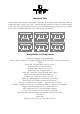
Important Note Using modern RAID Systems significantly increases data security and availability. Under no circumstances does it relieve you from a careful and daily backup on tape or a similar backup media. This is the only method to protect your valuable data against total loss (e.g. through fire or theft), accidental deletion, or any other destroying impacts.
Table of Contents A. INTRODUCTION.............................................................................................................. 13 A.1 Product Identification ................................................................................................. 13 A.1.1 Available RAIDYNE Upgrades ............................................................................. 16 A.1.2 Key Features of the GDT-Series Controllers ....................................................... 16 A.
B.5 Installing the GDT controller ...................................................................................... 51 B.6 GDT controller Function Check.................................................................................. 52 B.6.1 PCI 2.x Compatibility Requirements .................................................................... 52 B.6.2 Switching On the PCI Computer System ............................................................. 54 B.6.3 Trouble Shooting .........................
D. USING MICROSOFT MS-DOS...................................................................................... 131 D.1 Transparency of Host Drives ................................................................................... 131 D.2 Partitioning a Host-Drive and Transferring MS-DOS............................................... 131 D.3 CONFIG.SYS and the Driver GDTX000.EXE.......................................................... 135 D.4 Expanded Memory Managers.......................................
G.1 Transparency of Host-Drives................................................................................... 156 G.2 General Tips for Installation..................................................................................... 156 G.3 SCO UNIX System V/386 3.2v2.0 ........................................................................... 156 G.4 SCO UNIX System V/386 3.2v4.x & 3.2v5.x ........................................................... 157 G.4.1 GDT as additional Controller..............
J.5 Installation of a Removable Hard Disk ..................................................................... 179 K. THE DIAGNOSIS PROGRAM GDTMON ...................................................................... 182 K.1 Loading GDTMON ................................................................................................... 183 K.1.1 Loading the GDTMON program under Netware ................................................ 184 K.1.2 Loading the GDTMON program under OS/2.......................
K.3.6.7 Hot Plug: Remove Pool Hot Fix Drive....................................................... 234 K.3.6.8 Pool Hot Fix Access.................................................................................. 234 K.3.7 Save Information ................................................................................................ 235 M. GDTSETUP IN DETAIL................................................................................................. 240 M.
N.3 Assignment of the LED connectors ......................................................................... 292 N.4 Index ........................................................................................................................ 293 FCC Compliance Statement Information for the User NOTE: This equipment has been tested and found to comply with the limits for a Class B digital device, pursuant to Part 15 of the FCC Rules.
Chapter A General Information 12 Chapter A - GDT User's Manual
A. Introduction GDT Series: Hardware RAID Disk Array Controller for PCI Bus Computersystems with FAST SCSI, Wide SCSI or Wide & Ultra SCSI I/O channnels In order to take full advantage of modern operating systems, high performance computer systems are needed. When assessing the performance of a computer system, the aspects speed and security of the mass-storage subsystem are gaining increasing impo rtance.
FAST SCSI RAID Controllers Part Number 6001 6017 6002 6027 6037 6057 Part Name GDT6110 GDT6510 GDT6120 GDT6520 GDT6530 GDT6550 Number of FAST SCSI channels 1 1 2 2 3 5 RAID Levels 0, 1 0, 1, 4, 5, 10 0, 1 0, 1, 4, 5, 10 0, 1, 4, 5, 10 0, 1, 4, 5, 10 The GDT series of FAST SCSI RAID Controllers feature 1, 2, 3, or 5 FAST SCSI (8 Bit parallel SCSI) RISC processors. When appropriate SCSI devices are used, a synchr onous data transfer rate of up to 10MB/sec. can be achieved.
SCSI bus width Mode 8 Bit, narrow 16 Bit, narrow Fast Fast Synchronous data transfer rate 10 MB/sec. 10 MB/sec.
SCSI bus width Mode 8 Bit, narrow 8 Bit, narrow 16 Bit, narrow 16 Bit, wide 16 Bit, wide Fast Fast-20, Ultra Fast Fast Fast-20, Ultra Synchronous data transfer rate 10 MB/sec. 20 MB/sec. 10 MB/sec. 20 MB/sec. 40 MB/sec. A.1.1 Available RAIDYNE Upgrades The GDT6110 can easily be upgraded to a GDT6510. Order the RAIDYNE Upgrade with part no. 8710. The GDT6120 can easily be upgraded to a GDT6520. Order the RAIDYNE Upgrade with part no. 8720.
Wide SCSI RAID Controller: 2MB (GDT6115, only) to 64MB. Wide & Ultra SCSI RAID Controller: 2MB (GDT6117, only) to 64MB. One standard 72 PIN, 32 Bit or 36 Bit PS/2 SIMM, automatic Cache RAM dete ction. 9 Optional ECC Support for a single IBM ECC SIMM, available for the 5 channel Wide and Wide & Ultra SCSI RAID Controllers. 9 Intelligent multi-level cache-algorithm with adaptive delayed write and read ahead functions. This ensures an optimized cache for various load profiles and system requirements.
A.2 Copyrights, Patents The product ICP GDT is protected under international copyright laws and agreements. No part of this product or the manual, or parts of the manual may be reproduced in any form, physical, electronic, photographic, or otherwise, without the expressed written consent of vortex Computersysteme GmbH. For this product a patent is registered at the Deutsches Patentamt in Munich with the official reference no. 4121974.
A.3 Software License Agreement Please read this user agreement before opening the disk packaging and before starting to use the programs. Each loading of a program covered by this license agreement, each transmission within any existing network to another computer, as well as each copy on a mass storage system, regardless of what kind (floppy disk, hard disk etc.), represents a d uplication of the program according to copyright regulations.
A.4 General Information The GDT controller should be installed by an authorised ICP-vortex distributor. Precond ition for the safe installation is an antistatic work place (earthed mat on the table with wrist bands connected to an earth). ICP-vortex does not take any responsibility for damage arising out of improper installation. This manual contains all the information available at the time it was written. Errors and/or incomplete information are possible.
A.5 Product Description A.5.1 Transputer as Control CPU Transputer processors have gained wide acceptance wherever data has to be processed in parallel, or where processors are linked in a simple way. The transputer on the GDT co ntroller can reach a performance of 20 MIPS and is therefore superior to most standard processors used in such applications. The transputer on a GDT controller supervises all tasks of the SCSI devices, the RAID controlling and the communication with the PCI co mputer.
Wide SCSI RAID Controllers 20MB/sec. Wide & Ultra SCSI RAID Controllers 40MB/sec. The GDT controller is equipped with a SCSI-2-compliant (alternative 2), active, and softwareswitchable SCSI bus termination. A.5.6 GDT Controller Firmware and PCI-BIOS The firmware and the BIOS of the GDT controller are stored in a Flash-RAM on the GDT controller PCB. The firmware is designed for parallel processing and it controls all r esources of the GDT controller.
• On-line changes of SCSI device parameters (SCSI protocol, Disk Cache, Tagged Queues, synchronous/asynchronous transfer, transfer rate) • On-line check of the parity information of RAID 4 and RAID 5 disk arrays • Hot-Plug and Hot-Fix • Saving all configuration data to floppy disk or hard disk A.5.9 Driver Software Driver software for the following operating systems are included with the controller (L=included upon delivery; BBS=can be downloaded from our BBS): MS-DOS (Versions 3.3 to 6.
FAST SCSI RAID Controller: GDT6110/GDT6510 Overall View ➀........SCSI connector ➁........External SCSI connector ➂........72 PIN SIMM; 70ns ➃........Terminator Power channel A ➄........LEDs: T(green)=DMA; A(yellow)=Activity SCSI channel A; S(green)=Status OK ➅........LED connector channel A ➆........Flash-RAM for Firmware/BIOS ➇........Electronic loudspeaker ➈........
FAST SCSI RAID Controller: GDT6120/GDT6520 Overall View ➀........SCSI connectors A,B ➁........External SCSI connector channel A ➂........72 PIN SIMM;70ns ➃........Terminator Power channels A,B ➄........LEDs: T(green)=DMA; A,B (yellow) =Activity SCSI channels A,B; S(green)=Status OK ➅........LED connector channels A,B ➆........Flash-RAM for Firmware/BIOS ➇........Electronical loudspeaker ➈........
FAST SCSI RAID Controller: GDT6530 Overall View ➀........SCSI connectors A-C ➁........External SCSI connector channel A ➂........72 PIN SIMM;70ns ➃........Terminator Power channels A-C ➄........LEDs: T(green)=DMA; A-C (yellow) =Activity SCSI channels A-C; S(green)=Status OK ➅........LED connector channels A-C ➆........Flash-RAM for Firmware/BIOS ➇........Electronical loudspeaker ➈........
FAST SCSI RAID Controller: GDT6550 Overall View ➀........SCSI connectors A-E ➁........External SCSI connector channel A ➂........72 PIN SIMM;70ns ➃........Terminator Power channels A-E ➄........LEDs: T(green)=DMA; A-E (yellow) =Acivity SCSI channels A-E; S(green)=Status OK ➅........LED connector channels A-E ➆........Flash-RAM for Firmware/BIOS ➇........
Wide / Wide & Ultra SCSI RAID Controller: GDT6115/GDT6515 and GDT6117/GDT6517 Overall View ➀........SCSI connector for 8 Bit cable ➁........External SCSI connector for 16 Bit cable ➂........72 PIN SIMM;70ns ➃........Terminator Power channel A ➄........LEDs: T(green)=DMA; A(yellow)=Activity SCSI channel A; S(green)=Status OK ➅........LED connector channel A ➆........Flash-RAM for Firmware/BIOS ➇........Electronic loudspeaker ➈........Socket for the RAID GAL ➉........
Wide / Wide & Ultra SCSI RAID Controller: GDT6125/GDT6525 and GDT6127/GDT6527 Overall View ➀........ SCSI connectors A,B for 8 Bit cable ➁........ External SCSI connector channel A for 16 Bit cable ➂........ ➃........ ➄........ 72 PIN SIMM;70ns ➅........ ➆........ ➇........ ➈........ ➉........
Wide / Wide & Ultra SCSI RAID Controller: GDT6535 and GDT6537 Overall View ➀........ SCSI connectors A,B,C for 8 Bit cable ➁........ External SCSI connector channel A for 16 Bit cable ➂........ ➃........ 72 PIN SIMM;70ns ➄........ LEDs: T(green)=DMA; A,B,C (yellow) =Aktivity SCSI channels A,B,C; S(green)=Status OK ➅........ ➆........ ➇........ ➈........ ➉........
Wide / Wide & Ultra SCSI RAID Controller: GDT6555 and GDT6557 Overall View ➀........ SCSI connectors A-E for 16 Bit cable ➁........ External SCSI connector channel A for 16 Bit cable ➂........ ➃........ 72 PIN SIMM;70ns ➄........ LEDs: T(green)=DMA; A-E (yellow) =Aktivity SCSI channels A-E; S(green)=Status OK ➅........ ➆........ LED connector channels A-E Terminator Power channels A,B,C Flash-RAM for Firmware/BIOS ........
Chapter B Hardware Installation 32 Chapter B - GDT User's Manual
B. Hardware Installation B.1 Before the Installation The GDT controller is designed for minimum power consumption and maximum operational security. It therefore contains delicate electrical components (CMOS ).
fast page mode SIMM with at least 70ns or less, is needed. You can use single- and doublesided SIMMs. When using double-sided SIMMs with a high power consumption special care should be taken that both, GDT Controller and SIMM are properly cooled. It is not possible to operate the GDT controller without Cache-RAM. SIMM types which can be used on the GDT controller : FAST SCSI RAID Controllers SIMM Type min.
B.4 What you should know about SCSI It is very important for you to observe the information and notes given in this section of the Users Manual because it helps to ensure that the SCSI devices that are used in connection with the GDT Controllers are operated in a successful, long-lasting and trouble-free ma nner. In many cases this information is not only applicable to GDT Controllers but in general to all those SCSI systems which, like the GDT Controllers, use Single Ended SCSI bus channels.
SCSI Bus Width SCSI Mode 8 Bit, narrow 8 Bit, narrow 16 Bit, narrow 16 Bit, wide 16 Bit, wide Fast Fast-20, Ultra Fast Fast Fast-20, Ultra Synchronous Data transfer Rate 10 MB/sec. 20 MB/sec. 10 MB/sec. 20 MB/sec. 40 MB/sec. Number of Participants 8 4 8 8 8 Maximum Length 2.0 m 1.5 m 2.0 m 2.0 m 1.5 m With regard to Fast-20 devices, the maximum number of participants and the maximum cable length have to be strictly observed when a Fast-20 device (even if it is only one) is running in Fast-20 mode.
Example for a SCSI flat ribbon cable for 8 Bit SCSI devices (narrow) 37 Chapter B - Hardware Installation
Example for a SCSI flat ribbon cable for 16 Bit SCSI devices (wide) 38 Chapter B - GDT User's Manual
Example for a SCSI round cable for 16 Bit SCSI devices (wide) 39 Chapter B - Hardware Installation
B.4.2 SCSI Termination In order to ensure a flawless and interference-free signal transmission on the SCSI bus and to minimize the detrimental effects of external noise generators, both ends of the SCSI c able, and they only, have to be terminated. The SCSI specification prescribes two alternative termination modes for Single Ended SCSI bus systems: the passive termination and the active termination, also known as Alternative-2 termination.
• FAST SCSI GDT RAID Controllers GDT6110, GDT6120, GDT6510, GDT6520, GDT6530 and GDT6550 Valid connections and required GDTSETUP settings for channel A External female connector, 50 pin Internal 50 pin male connector channel A Channel A termination Occupied and end terminated Occupied and end terminated Not occupied Not occupied Occupied and end terminated Not occupied Occupied and end terminated Occupied and both ends terminated. Channel A connector is located between the two ends.
Not occupied connector is located between the two ends.
• • • All participants of a SCSI bus must have a different SCSI ID. The factory set SCSI ID of the GDT controller SCSI channel is 7. Up to 7 SCSI devices can be connected to a single SCSI bus. SCSI IDs are 0, 1, 2, 3, 4, 5, and 6 . On hard disks, CD-ROMs, tape streamers, etc., the SCSI ID is normally set through jumpers or small DIP switches. The GDT controllers offer a far more comfortable method: software switches in the GDTSETUP program allow you to easily set the SCSI ID of a GDT SCSI cha nnel.
One internal SCSI device on channel A of a FAST SCSI RAID Controller. GDT6wx0 (e.g. GDT6510).
Several internal SCSI devices on channel A of a FAST SCSI RAID Controller. GDT6wx0 (e.g. GDT6530).
One internal and one external SCSI device on channel A of a FAST SCSI RAID Controller. GDT6wx0 (e.g. GDT6120).
One internal 16 Bit SCSI device on channel A of Wide SCSI or Wide & Ultra SCSI RAID Controller. GDT6wx5/7 (e.g. GDT6517).
Several internal 16 Bit SCSI devices on channel A of a Wide SCSI or Wide & Ultra SCSI RAID Controller. GDT6wx5/7 (e.g. GDT6117).
Two internal SCSI devices (16 Bit and 8 Bit) on channel A of a Wide SCSI or Wide & Ultra SCSI RAID Controller. GDT6wx5/7 (e.g. GDT6517).
One internal and one external SCSI device (both 16 Bit) on channel A of a Wide SCSI or Wide & Ultra SCSI RAID Controller. GDT6wx5/7 (e.g. GDT6515).
B.5 Installing the GDT controller Step 1 Switch off the PCI computer system and remove all cables (first of all the power supply). Step 2 Following the instructions of the computer manual, open the case of the PCI computer, so that you have easy access to the PCI expansion slots. Step 3 Select a free PCI bus-master slot and remove the metal bracket, following the instructions in your PCI computer manual.
the SCSI cable may be used by SCSI devices which do not supply DC power to their own SCSI termination circuitry (e.g. external SCSI terminator packs.). Step 7 When installing internal SCSI devices, make sure that the slots of the SCSI devices have a sufficient air flow, and that the power consumption of all SCSI devices does not exceed the capacity of the computer's power supply.
We have observed more than once that a motherboard declared fully PCI 2.x compatible was equipped with a System-BIOS (located in an EPROM or FLASH-RAM) which was not PCI 2.x compatible at all. To make up for this, many manufacturers of PCI motherboards or PCI computer systems offer their customers a BBS mailbox system from where the latest PCI-system-BIOS version can be downloaded by modem.
B.6.2 Switching On the PCI Computer System Now, after having installed the GDT controller and the SCSI devices, we check whether the controller is working correctly. If the GDT controller is the only controller in the computer system, set hard disks C: and D: to not available in the System-BIOS setup program of the computer. Normally, you can start the BIOS setup program by pressing a certain keycombination after switching on the computer.
[PCI 0/3] PCI device, bus system 0, slot 3. The PCI 2.x specification allows several PCI bus systems to be present in one PCI computer. To our knowledge, currently there are only computers with one PCI bus system (having 2, 3, or 4 PCI-slots). Nevertheless, as this may change in the future, all GDT controllers have been designed to support multiple PCI bus system co mputers.
If the PCI System-BIOS is not PCI 2.x compatible (see above), the GDT controller BIOS may display one or more of the following messages: (i) The DPMEM has not been installed correctly. Error: System-BIOS not PCI compliant (contact your mainboard supplier) Controller at x/y has invalid DPMEM address 012345. Trying to allocate a free address.
Function Delayed Write Interrupt BIOS BIOS Warning Level DPMEM Mapping Memory Test SCSI-ID SCSI Termination Possible Settings On, Off Line A Enabled, Disabled All messages, Fatal errors PCI compliant No Test, Standard, Double Scan, Intensive 0,1,2,3,4,5,6,7 On, Off, Auto Factory Setting On Line A Enabled All messages PCI compliant Standard 7 On B.7.1 Starting GDTSETUP Boot the MS-DOS operating system (either from a boot-floppy or from an already existing boot drive, for example an IDE-hard disk etc.).
Note: In order to get the full performance of your GDT controller, it is essential that the Delayed Write option of the GDT controller is set ON, too. If you should find different settings here, we recommend to change them now. B.7.2 Updating the GDT Controller with new Firmware and BIOS Versions The firmware and the BIOS of the GDT controller are stored in a Flash-RAM which is part of the GDT hardware.
be easily updated without having to remove the controller from its PCI slot. Both modules (Firmware and BIOS) are part of the so-called EPROMLIB. An EPROMLIB named EPROMLIB.Rxy (e.g. EPROMLIB.R19) belongs to a GDT controller with RAIDYNE. An EPROMLIB named EPROMLIB.Nxy (e.g. EPROMLIB.N2A) refers to a GDT controller without RAIDYNE. (Note: An EPROMLIB file with the extension R... may only be programmed into a GDT controller which has the RAID GAL installed.
B.6.3 Additional Notes After having completed the installation, you can close the computer case again. The following chapters explain how to configure the SCSI devices and how to use the GDT co ntroller with various operating systems. VERY IMPORTANT NOTE: Before the computer is switched off or a hard reset is carried out, the GDT controller first has to write the current contents of its cache RAM back to the hard disk(s) (flush).
This page intentionally left blank.
Chapter C Quick-Setup 62 Chapter C - GDT User’s Manual
C. Quick-Setup C.1 What is the Aim of Quick-Setup ? In the previous chapter we have installed the GDT controller in a PCI computer and co nnected the SCSI devices. Now these SCSI devices must be prepared in order to run with your operating system. This Quick-Setup chapter should help you to get started quickly.
Before we go through these examples step by step, we would like to explain a few terms and relations important for the basic understanding of the GDT firmware. At the end of e xample 4, we will try to answer the three questions above. C.2 What is the GDT controller Firmware ? We refer to firmware as the operating system which controls the GDT controller with all its functions and capabilities. The firmware exclusively runs on the GDT controller and is stored in the FLASH-RAM on the GDT controller PCB.
controller firmware (which are the same for both firmware versions: Standard and RAIDYNE). C.3.1 The Express Setup Function of GDTSETUP EXPRESS Setup does not require any previous knowledge. If you choose this function, GDTSETUP carries out the complete installation entirely on its own, giving you for example a fully operational RAID 5 Disk Array with optimized settings (for instance, with all SCSI features of a given drive activated).
C.4 Levels of Hierarchy within the GDT Firmware Both GDT firmware versions (Standard and RAIDYNE) know three fundamental levels of hierarchy. Each level has its "own drives" ( = components). The basic rule is: To build up a drive on a given level of hierarchy, the drives of the next lower level of hierarchy are used as components. Level 1: (1) Physical SCSI drives = hard disks, removable hard disks, some MO drives are located on the lowest level. The GDT firmware refers to these drives as disks.
you to continue your work without having to wait. The firmware will always ensure that both drives contain identical data. If a drive should fail during your working session, the fir mware is able to continue to work without interruption because it uses the second drive. RAID 1 is a rather expensive method of redundancy because it requires the double number of drives. It is a distinctive characteristic of the firmware that all cache drives receive their own number, the so-called cache drive number.
Now here are the examples which explain step by step all the necessary basics for setting up host drives with your GDT controller. C.6 Example 1 - Installing a single SCSI Hard Disk This example is applicable to all GDT controllers. We presume that the controller and the SCSI hard disks have been installed properly. Step 1: Starting GDTSETUP Boot the MS-DOS-operating system (either from a boot-floppy or from an already existing boot drive, i.e. IDE-hard disk etc.).
Step 2: Initializing the SCSI Hard Disk Now activate the menu Initialize Disks (level 1). A list appears showing all hard disk drives found on the GDT controllers SCSI channels (in our example two drives). If you have a GDT controller with a different number of SCSI channels, the existing SCSI channels are di splayed.
1. Formatting and surface test: OFF. All manufacturers of SCSI hard disks deliver their products already formatted and surfacetested. The formatting and surface test of a hard disk takes quite a long time; these procedures are only indicated if you have doubts on the disk drive's condition. 2. Sync. Transfer: Enable The SCSI-bus knows two methods of data transfer: asynchronous and synchronous transfer . Every SCSI-device must be able to perform the first type of transfer, the second one is o ptional.
command at a time). Enable all features if this is possible without conflicts. Then leave this screen buy pressing < OK >. The maximum synchronous transfer rate can be limited. This limitation may become necessary if a particular SCSI cabling does not allow the maximum rate the drive and the co ntroller could achieve. In our example, we leave the rate at 10.0 MByte/s (for Wide SCSI at 20.0 MBytes/s and Wide & Ultra SCSI at 40.0 MBytes/s) and press .
We are now back on the main screen of level 1 and see that the initialisation-status of the SCSI-device has changed. Step 3: Setting Up the Cache Drive We now leave level 1 (by pressing the ESC-key) and are back in the main menu. Now, with the cursor keys ↑ and ↓ select Set Up Cache Drives and go to level 2 by pressing .
The main screen of level 2 appears: Available Cache Drives of the Co ntroller This screen is the starting point for all further installation procedures on level 2. At the moment, the selection line marks field no. 2, Press . The cache drive in field no. 0 is an already existing cache drive from a previous installation and not relevant for our e xample.
Press again and we obtain the list of all SCSI-devices available for creating a cache drive (in our case it is only one initialized SCSI drive). Move the selection line with cursor keys ↑ and ↓ to the first device and press the SPACEbar to mark your choice (pressing the SPACE-bar again undoes your choice). When the d evice is selected, confirm your choice with . For security reasons you will be asked again if you want to use the selected SCSI-devices to create a cache drive.
As we are sure of our choice, we confirm with . The dialog box is closed and we are back in the main menu of level 2. As you can see, we have already created a cache drive of the type disk. The name of the cache drive is assigned automatically and contains the channel description and the SCSI-ID after the "_" . This can serve as a reminder when you install a complex system with many drives. (Naturally, you may change the name.) This concludes the installation on level 2.
Step 4: Configuring a Host Drive We are now back in the main menu of GDTSETUP and select Configure Host Drives. The main screen of level 3 appears: As already mentioned earlier, all newly installed cache drives are automatically tran sformed into host drives, too.
stalled on level 2. This step was not really necessary, as we only have one single cache drive which at the same time became a host drive. It is exactly on this level 3 where we shall configure RAID disk arrays with examples 3 and 4. Step 5: Leaving GDTSETUP We are now back in the main menu of GDTSETUP. The installation is completed, and we therefore leave GDTSETUP by pressing the ESC-key.
C.7 Example 2 - Installing a Mirroring Array This example is applicable to all GDT controllers. It is our intention to install a Mirroring Array consisting of two identical hard disks. We presume that the controller and the SCSI hard disks have been properly installed. Step 1 of the installation is the same as in the first example, therefore we do not explain it again. Step 2 regards the initialisation of the second SCSI device. Proceed as described in the first example.
This screen is the starting point for all future installation procedures on level 2. The selection line marks field no. 0. Press . Press again. We obtain a list of all SCSI-devices presently available for creating a cache drive (in our case one initialized SCSI drive).
Move the selection line with the cursor keys ↑ and ↓ to the first device and press the SPACE-bar to mark your choice (pressing the SPACE-bar again undoes your choice). When the device is selected, confirm with . For security reasons you will be asked to confirm that you want to use the selected SCSI-devices to create a cache drive. We confirm with . We are back in the main menu of level 2.
As you can easily recognize we have already created another cache drive of the type Disk. Its name is created automatically and contains the channel description and the SCSI-ID of the first SCSI-device after the "_". This can serve as reminder when you install a complex sy stem with many drives. (Naturally you may change the name.). Our objective is to add the second cache drive as a mirror drive to the first cache drive (master) of the list.
Next, choose the command Add Mirror Drive and press . The screen displayed now contains the list of available Mirror Drives. Select the displayed cache drive and press . As we are sure of our choice we co nfirm the security request.
You can see that the Available Cache Drives list shows only one entry now. It is our mirroring array which is nothing else but a cache drive of the type Mirror consisting of two cache drives of the type disk. The characters "v*" indicate that the data consistency has not been generated yet. The sequence of these two characters (v before *) corresponds to the sequence of the cache drives forming the mirroring array.
for it depends on the drives' capacity and the controller's load), the status of the mirroring array turns to "vv", that is, both cache drives are "valid" and contain exactly the same data. This concludes the installation procedures on level 2. Now press the ESC-key to leave this screen. Steps 4 and 5 are the same as in example 1. C.8 Example 3 - Installing a RAID 5 Disk Array This example is applicable to GDT controllers with the RAIDYNE firmware.
Also three SCSI-cables are needed. The cables for channel A, B and C have three conne ctors, where one connector of channel B is used by a drive which is not relevant for our e xample. Please note: bad SCSI-cables, wrong SCSI-IDs as well as a wrong termination of the busses are responsible for 95% of all possible errors! In addition, it is essential that the disk drives and the controller be connected to the SCSIcable with the right orientation.
Partial step 2: Initialize the SCSI Hard Disk Now activate the menu Initialize Disks (level 1). A list appears displaying all hard disk drives found on the SCSI channels of the GDT controller (in our example five drives). Note: This screen gives a complete listing of all devices found on the SCSI-cables. However, with GDTSETUP we can only work on Direct Access Devices, hence not on CD-ROMs etc..
• to which channel a drive is connected • which SCSI-ID the drive has (the entry SCSI I/O Processor stands for the corresponding SCSI channel of the GDT controller. It has the default setting ID 7, as explained in cha pter B) • the initialisation status • the SCSI name of the drives • the Read-Write-Status. [RW] = Read + Write • the gross capacity There is one drive on channel B which has been initialised already before and which is not relevant for this example.
transfer between them is possible. Therefore, the mere setting does not automatically enable synchronous data transfer; this mode is only effective if both devices support it and after they have checked their capability of communicating with each other in this mode. 3. Disconnect: Enable The concept of the SCSI-bus allows several participants (8 IDs with 8 LUNs each). All these participants should be able to use the bus in a manner that causes the least reciprocal di sturbance or obstruction.
The warning of the destruction of all data implies different evaluations, according to the drives current state and the options you have selected in the dialog box: 1. First Initialisation of the SCSI Device. In this case the warning must be taken seriously. If the drive was previously connected to a different controller (e.g. Adaptec etc.) and still contains data, this data will be lost now. 2. Format Disk and/or Surface Check enabled.
Initialise the remaining four drives as described above, that is: • Select the device with the cursor keys ↑ and ↓ and press the ENTER-key • Choose the settings shown above • carry out the initialisation When the initialisation of the last SCSI device has been completed, the screen should look as follows (a small i (i = initialised) must follow the SCSI-ID of each SCSI device): 90 Chapter C - GDT User’s Manual
Important: Moving to the next level (Set Up Cache Drives) only makes sense if all SCSI d evices you need there are initialised. Partial step 3: Setting Up Cache drives We now leave level 1 (by pressing the ESC-key) and are back in the main menu. With the cursor keys ↑ and ↓ select Set Up Cache Drives and enter level 2 by pressing .
This screen is the starting point for all further installation procedures on level 2. At the moment, the selection line marks field no. 2, and we confirm with . Note: The entry in line no.= is not relevant for our example. We press the ENTER-key again and obtain Here all the SCSI-devices available for creating a cache drive are listed.
(pressing the SPACE-bar again undoes your choice.) We start with the first device listed. After having marked the device, confirm your choice with . For security reasons you will be asked to confirm that you intend to use the marked SCSI-device to create a cache drive. As we are sure of our choice, we confirm with . The screen disappears and we are back in the main menu of level 2.
As you see, we have created a cache drive. Its name has been assigned automatically and it contains the channel description and the SCSI-ID after the underscore ("_"). This can serve as reminder when you install a complex system with many drives. (Naturally you can change the name.) Now set up the remaining cache drives one by one.
The main screen of level 3 appears: As mentioned before, all newly installed cache drives are automatically transformed into host drives. For this reason we now see the five new cache drives installed on level 2. I nstalling a RAID 5 disk array now is easy as can be. With the selection bar, choose the first drive with which you want to start the disk array setup (in our example, DISK_A4).
Since we want to install an array drive, we select the command Set Up Array Drive. Another selection menu appears, offering all the functions needed to set up and configure an array drive.
In this menu the first entry of the list is already selected (host drive DISK_A4), because it has been chosen as the Master (starting point) of the array drive. Now select all remaining host drives which are to be part of the array, moving the selection bar with the cursor keys ↑ and ↓ to the next host drive and pressing the SPACE-bar, etc. . After having selected all the host drives, press . • GDTSETUP now asks you what kind of disk array you wish to create.
RAID 0 RAID 4 RAID 5 RAID 10 pure data striping without redundancy data striping with dedicated parity drive data striping with striped parity RAID 0 combined with RAID 1 In our example, we choose RAID-5 Striped Parity.
GDTSETUP asks for the Stripe Size. This is the size of the stripes into which the data is divided. The default is 32KB which we leave for this example and therefore press . (Note: 32KB stripe size is suggested because in various performance tests it has proved to be the best value.). The disk array is now given a name. GDTSETUP suggests "RAID5". We accept this name and press . Before proceeding with the creation of the new disk array, GDTSETUP asks you to confirm your decision.
We do want to create a disk array, so we confirm the request with . It's done ! We succeeded in setting up a RAID 5 disk array. The screen shows that the disk array is cu rrently in an idle status. Later in this chapter we shall explain the different statuses a RAIDYNE disk array can assume.
We are now back in the main menu of GDTSETUP. All installation procedures are completed, and therefore we leave GDTSETUP by pressing the ESC-key. The following message appears: As we are done with the installation and therefore definitely want to leave GDTSETUP, we select . GDTSETUP now starts to create the just configured disk array. The Progress Information box indicates how long this procedure takes.
At the end of this Array Build we press . GDTSETUP now checks if you have made changes to the system configuration which r equire a warm reboot of the system. This is true for our example. IMPORTANT: Always end GDTSETUP by leaving the program in the regular way (do not warm boot with CTRL-ALT-DEL or cold boot by pressing the RESET button). Ce rtain information is only transferred to the controller when you quit GDT SETUP in the regular way.
The status of the disk array named RAID5 is ready and therefore fully operational. Now change to the sub menu Set Up Array Drive. Press the function key F2, and all relevant information on the disk array's configuration is displayed.
Press the ESC-key to leave this screen and select Parity Verify. RAIDYNE now checks the correctness of the redundancy information.
Depending on how large the disk array is, this check may take quite a time, however, it can be aborted by pressing . Parity Verify is a diagnosis function which enables you to verify the consistency of a disk array every now and then. We interrupt the verifi cation by pressing . Note: The GDT monitor program GDTMON also includes the parity verify function. Unlike in GDTSETUP, the disk arrays parity can be checked while the disk array is fully operational (e.g. in a NetWare file server).
The alarm signal does not switch off because the disk array, although operational, is found in a status without redundancy, that is, a status which should be eliminated as soon as possible. The alarm signal turns off when GDTSETUP is loaded. How is this situation reflected in GDTSETUP ? What has happened to the failed disk drive ? To answer these questions, we load GDTSETUP and check. We go to the menu Configure Host Drives and find the following main form: As expected, the disk array is in a fail status.
What has happened to the failed disk drive? First of all, we take a look at the list of the cache drives: As expected, disk drive no. 1 (DISK_B2) is fault. Important: Even if we reconnected the power supply to DISK_B2 before loading GDTSETUP, DISK_B2 would not be included into the disk array again. If you decide to use the failed disk drive again, it is best if you reconnect the drive to the power supply and do a cold boot.
After loading GDTSETUP select the Configure Host Drives menu. In the Set Up Array Drive menu select the Replace Drive option. Move the selection bar to the failed drive and press . GDTSETUP recognizes the previously failed drive again (it was not really defective) and asks if it should be integrated into the disk array agian.
Answer and the disk array changes its status into rebuild. After leaving GDTSETUP the controller begins the reconstruction of the data of the failed drive. After the completion of this process, the disk array's status changes into ready again. A few words on the replacement of a defective disk drive if a disk array. If a disk drive belonging to a disk array for which no hot fix drive had been assigned should fail, you should replace this defective disk drive with a new one as soon as possible.
be aware of the fact that this disk array does not have any redundancy until the defective disk drive has been substituted. This means that if another disk should fail while the disk array is without redundancy, all data is irretrievably lost. RAIDYNE offers two possibilities of replacing a failed drive of an array for which no Hot Fix drive has been de signated: 1. Replacement with GDTSETUP (we have just demonstrated this method) 2.
Again we see that GDTSETUP has turned all cache drives into host drives. As in example 3, we highlight the host drive with which we want to start to create the disk array. We choose the first entry (DISK_A4) and confirm by pressing ENTER (the host drive boot_me is not relevant for our example).
As we want to configure an array drive, we highlight the option Set Up Array Drive and press . Another dialog box is shown, displaying all the settings necessary for configu ring an array drive. As you want to create a new disk array, highlight Create Array Drive.
In this form the first option (disk drive DISK_A4) is already highlighted because this disk has previously been chosen as the drive with which to start the array-setup. Now select all other host drives which are to be part of the disk array. The selection is made as usual, moving the cursor with ↑ and ↓ to the selected host drive and pressing the SPACE-bar, then continuing in the same manner in order to choose the next host drive. In this way, select all drives except DISK_C2.
GDTSETUP will now ask you what type of disk you want to create. Since we want to have a RAID 5 Disk Array, select the corresponding menu item. GDTSETUP asks for the Stripe Size. This is the size of the stripes into which the data is divided. The default is 32KB which we leave for this example and therefore press . (Note: 32KB stripe size is suggested, because in various performance tests it has proved to be the best value.).
The Disk Array receives a name. We simply accept GDTSETUP's suggested name RAID5. Confirm the security request with . Now we are back in the main menu. The controller has three host drives now: the RAID 5 Disk Array which we have just created, and the remaining single drive which will now be designated to serve as a hot-fix drive. The boot_me host drive is not relevant for this exa mple.
Partial step 5: Creating a Hot Fix drive Move the cursor to the array drive to which you want to assign a Hot Fix drive. In our exa mple, we only have one disk array, so we select it and confirm with . Again, the a lready familiar "Host drive configuration" sub-menu appears. We select Set Up Array Drive to obtain the following submenu: This submenu allows you to carry out all changes and servicing necessary for an array drive. Our objective is to set up a Hot Fix drive for our RAID 5 Disk Array.
light the item Add Private Hot-Fix Drive, and confirm by pressing . GDTSETUP now displays a new dialog-box containing all the host drives apt to serve as a hot-fix drive (one criterion for this suitability is the drive's capacity, i.e., it has to be large enough). So don't be surprised if at later installations you do not find all the drives you would have expected. GDTSETUP does know which drives are suited to be used as hot-fix drives.
GDTSETUP will therefore ask you whether you are sure of your choice. We are, so we co nfirm with . The dialog box disappears and we leave this configuration level with ESC. Again, we find ourselves on the level Host Drives of the Controller. Select our Disk Array, press and then press F2 to get the Configuration Data Sheet: We have already seen this form from before, with the only difference that DISK_C2 has been entered into the list of Hot Fix drives.
We now leave GDTSETUP as described in example no. 3, in order to allow GDTSETUP to send all relevant information to the controller and let RAIDYNE create and store the r edundant information. The question that arises now is: When and how does the Hot Fix mechanism work ? Normally, RAIDYNE puts Hot Fix drives in a stand-by mode, that is, their motors are stopped.
As expected, the disk array is in the rebuild status. Request the drive information regarding the RAID5 disk array with and then Two changes have occurred. The hot-fix drive DISK_C2 has disappeared from the list of Hot Fix drives (the status is missing), and DISK_C2 is now located in the Drive Component List and has the invalid status (i.e. the data are still under reconstruction).
As expected, drive no. 1 (DISK_B2) is missing. Leave GDTSETUP and when you are back at the MS-DOS prompt, switch of the system. We now want to add a new Hot-Fix drive to the disk array. For our example we take a brand new drive set its SCSI ID to 4 and connect it to the connector of SCSI channel B, where the previously failed drive was connected to and to the DC-power supply. Before switching on the system again, check the SCSI termination of the new drive to be identical with the old one.
In the next step we setup a new Cache Drive: 122 Chapter C - GDT User’s Manual
DISK_B4 is our new Cache Drive, which we want to use as a new Hot-Fix drive. Select the Add Private Hot-Fix Drive option. A list of suitable Hot-Fix drives is displayed. In our example we have only one choice, DISK_B4. We select the drive with the SPACE-bar and press .
As we can see from the Drive Component List, DISK_B4 has become the new Hot-Fix drive for our RAID5 disk array. C.10 Trying to answer the initial questions Now, after having demonstrated with examples 3 and 4 how RAID disk arrays are created with RAIDYNE (we hope you enjoyed it), we would like to return to the questions put at the beginning of this chapter. When planning a disk array it is essential that you have precise ideas on how you intend to configure the disk array.
RAID 4 RAID 5 RAID 10 data dtriping with parity drive data striping with striped parity data striping and mirroring 3 3 4 The desired usable disk space of the disk array as well as the following two issues have a direct impact on the number of physical disk drives needed. C.10.2 Which level of redundancy is needed ? To say it right away, RAID 0 (data striping) does not imply any redundancy at all (the R in front of the AID is rather misleading).
drives of the RAID 5 disk array we set up with example 1 fails. The disk array is without r edundancy. TWR starts to run. Any superfluous prolongation of the TWR (because you have to get a replacement drive, or because you did not realize the failure immediately since you didn't hear the GDT controller's alarm signal, or because nobody checked the file server) increases the risk of data loss which will occur if a second drive should fail.
C.11.5 Rebuild status The disk array will assume this status after the automatic activation of a hot-fix drive or after a manual replacement carried out with GDTSETUP. The data and the redundant information are reconstructed and stored to the new drive. C.11.6 Error status If a second disk drive should fail while the disk array is in the fail or rebuild status, it is not possible to continue the working session without restrictions.
(*) Replacement either manually, or through hot fix method.
This page intentionally left blank.
Chapter D Using Microsoft MS-DOS 130 Chapter D - User's Manual
D. Using Microsoft MS-DOS After having explained the installation of the GDT controller and the host-drives in chapters B and C, we now explain how to install the operating system MS-DOS. With some examples we shall demonstrate how to partition a host-drive, transfer MS-DOS to the host-drive, i nstall Windows 3.x and use a CD-ROM drive (exemplarily standing for any other Not Direct Access Device) under MS-DOS. In addition we will give you further information on how to i nstall Windows 95. D.
(C) Now, in the program GDTSETUP, select the menu Configure Host Drives. Pressing ENTER leads you to the following sub-menu. In our example, the host drive list contains one host drive only. We select this host-drive (by moving the selection line with the cursor keys ↑ and ↓) and confirm our choice with .
We now select the sub-menu Partition Host Drives, and the following screen appears. In our example, there is no entry yet. Now select Create Partition and press .
In the upcoming window, select Primary Partition and confirm with . On the next screen you can determine the size of the primary partition. In our example, we choose to use the entire disk capacity for the primary partition and therefore simply co nfirm with ENTER. On the following screen you see that the primary partition has been su ccessfully installed and that GDTSETUP has automatically assigned the active status (A) to this partition.
(D) Now leave GDTSETUP by pressing . After a few requests and messages from GDTSETUP, the system reboots. (E) Now use the MS-DOS program FORMAT to transfer MS-DOS to the primary partition you have just created. To do so, enter A:\> FORMAT C: /S (F) To complete the installation of MS-DOS, use the MS-DOS commands COPY or XCOPY to transfer the desired MS-DOS files. A different and maybe even more elegant method of installing MS-DOS is to use the SETUP program of MS-DOS versions 5 and 6.
✔ GDTX000.EXE is needed for an optimal use of Windows 3.x. ✔ The GDT controller unfolds its full capacity under MS-DOS or Windows 3.x only when GDTX000.EXE is installed. ✔ In order to load GDTSETUP, you need GDTX000.EXE ✔ In the CONFIG.SYS file GDTX000.EXE must be loaded before GDTXDOS.EXE and GDTASPI.EXE. (Both drivers use functions contained in GDTX000.EXE). ✔ GDTXDOS.
BIOS located at 0x00E0000 - 0x00E1FFF In this example, the GDT BIOS occupies E000:0000 to E000:1FFF (E000 is the segment a ddress). DPMEM at 0x000D0000 - 0x000D3FFF Here the DPMEM starts at D000:0000 and ends at D000:3FFF (D000 is the segment a ddress). You may also use other utility programs such as Georg Schnurers (ct magazine) CTPCI program in order to obtain the requested address locations. On this occasion we would like to thank Mr.
Now, delete those lines from the CONFIG.SYS and AUTOEXEC.BAT files which contain SMARTDRV.EXE (one line in each file) using an editor such as EDIT for instance which is part of MS-DOS 5 and 6, or deactivate these lines by entering REM at their beginning. Then save and exit the files. Next, load the SYSTEM.INI file located in the WINDOWS directory into the editor and look for the entry [386Enh].
slightly, depending on whether you use the corelSCSI software (by Corel) or the ASW software (by Adaptec). Regardless of which company's ASPI module you choose to use, the ASPI manager of the GDT controller (located on the GDT System Disk - DOS) has to be loaded from the CONFIG.SYS file.
that it is a CD-ROM drive). Information on the various CD-ROM drives which can be used can be obtained directly from adaptec. D.6.2 Example: Using corelSCSI for the NEC CD-ROM When using the corelSCSI software, the installation is carried out by a program ( install), so that the changes in the files CONFIG.SYS and AUTOEXEC.BAT mentioned below are, to a large extent, made automatically. Under corelSCSI the SCSI/FAST-SCSI channels of the GDT controller are available as independent host adapters.
In our example, we use a Wangtek 1.3GB drive. We presume that the DAT drive has been properly connected to the GDT controller. This includes that the SCSI-ID and the SCSI bus terminators have been set in accordance with the settings of the already existing SCSI d evices (i. e., the SCSI-ID set for the DAT drive is not occupied by another device; resistor terminators are located at the two ends of the SCSI bus only).
Step 3: Change to the directory to which you have transferred the ARCsolo files (default C:\ARCSOLO) and load ARCSOLO: C:\ARCSOLO\ARCSOLO Step 4: The main menu with the heading Available subjects appears. Choose the item Administration and then Configure Options. Available Subjects ↓ Administration ↓ Configure Options Configure Tape Driver View Activity Log Step 5: On the upcoming screen, set the entry Optimize Tape Performance to No. Step 6: Next, choose the submenu Configure Tape Driver.
H: I: x1, y1: host adapter number SCSI ID of the SCSI device to be reserved host adapter number, SCSI ID of the first SCSI device to be reserved (in decimal form) host adapter number, SCSI ID of the second SCSI device to be reserved (in decimal form) x2, y2: Example: We assume that there is only one GDT controller in the system.
The CONFIG.SYS will be similar to the file below (the relevant entries are printed bold). The parameters following the corelSCSI driver refer to a particular configuration, they have automatically been added by the corelSCSI INSTALL program. device=gdtx000.exe files=30 buffers=30 stacks=9,256 shell=\COMMAND.COM /E:512 /P device=\gdt\gdtxdos.exe device=\gdt\gdtaspi.exe /R:H1I4 device=\coreldrv\UNI_ASP.SYS /C:4 /ID:4;;;1 /VOL:1 /DOS4 /SS:512 /@4:-98 Note: drives run with corelSCSI and the UNI_ASP.
Chapter E Using IBM OS/2 v2.
E. Using IBM OS/2 Version 2.x and Warp After having exposed in chapters B and C the installation of the GDT controller as well as that of the host-drives, we would now like to give you some hints and pieces of advice on how to install IBM's operating system OS/2 Versions 2.x and Warp. Furthermore, we explain how to install a CD-ROM drive (representatively standing for any other Not Direct Access Device) under OS/2. E.
the OS/2 Boot-Manager, etc. . After having decided on these options, you can start the i nstallation beginning with DISK 1 of the copy set you have previously created. The OS/2 installation itself is carried out according to the OS/2 installation program. After having completed the installation, you should check that the OS/2 CONFIG.SYS file created during the OS/2 installation contains the following line: BASEDEV=GDTX000.ADD /V and that the driver GDTX000.
(Naturally BASEDEV=GDTX000.ADD has to be included in the CONFIG.SYS, too.). The name of the OS/2 CD-ROM driver (here CDROM_G.SYS) may be different, depending to the OS/2 version you have. E.4.2 Installation with OS2ASPI.DMD (A) Add the following line to the CONFIG.SYS file, using, for example, the OS/2 system editor BASEDEV=OS2ASPI.DMD (B) Now the driver GDTX000.
Switch for supporting an ASPI-Manager (i.e.: OS2ASPI.DMD) /AM Support SCSI-Devices (OS2ASPI.DMD) /AM:d Support Host-Drive d as ASPI-Device /AM:(d,e) Support SCSI-Device (Bus d, SCSI-ID e) as ASPI-Device /[!]AM... /NOSCAN Scans the SCSI channels only fur these devices, which are configured through the "/DM, /SM, /AM or /R switches. /[!]UT Ignores special time-out values of a certain application, but always uses the GDTX000.ADD settings. Some backup programs use time-out values that are too short.
This page intentionally left blank.
Chapter F Using Novell NetWare 151 Chapter F - Using Novell NetWare
F. Using Novell NetWare After having explained in chapters B and C the installation of the GDT controller as well as that of the host-drives, we would now like to give you some hints and pieces of advice on how to install Novell's operating system Novell NetWare. We shall mainly focus on Ne tWare 3.x and NetWare 4.x. For a successful installation it is essential to study the NetWare system manuals thoroughly. The information given in this chapter refers to the loading of the GDT NetWare driver only. F.
The GDT ASPI Manager ASPITRAN.DSK and the CTRLTRAN.DSK module will then be aut omatically loaded by the GDT driver (GDT6X310 or GDT6X311). If more GDT controllers are installed in the fileserver (i.e. for controller duplexing), the above mentioned driver has to be called upon several times. But as it is re-entrant, it is only loaded once. A single GDT controller can be chosen by selecting its PCI slot number.
is needed. When loading the regular GDT NetWare driver (for example GDT3x311.DSK), the ASPI Manager is automatically loaded, too. During the installation of ARCserve, choose Adaptec ASPI Manager as interface.
Chapter G Using SCO UNIX V/386 155 Chapter G - Using SCO UNIX V/386
G. Using SCO UNIX V/386 After having explained in chapters B and C the installation of the GDT controller as well as that of the host drives, we would now like to give you a few hints regarding the installation of the operating systems SCO UNIX V/386 3.2v2.0, 3.2v4.x, 3.2v5.x (Open Server) For a successful installation it is essential to read the SCO system manuals thoroughly. G.
First, install the GDT driver on the SCO UNIX system. To do so the system does not need to have a GDT controller installed yet. Install the driver with the help of the program custom. Log into the already running SCO UNIX system as root and start custom. Now, select the option Install, then A new Product, and finally Entire Product from the menu coming up. When requested, insert the GDT CUSTOM-disk and follow the instructions of the custom program.
chapter B, Hardware Installation). In addition, the GDT BIOS must not be disabled and the boot drive must be connected with the GDT controller having the lowest BIOS address. When the UNIX installation has been completed, the driver is installed, too, and you may install further devices with mkdev hd (ADM). G.4.1 GDT as additional Controller The installation of the driver is carried out with installpkg. G.5 Instructions on mkdev (ADM) for 3.2v2.0 & 3.2v4.
Therefore, this host drive has target-ID 0 and LUN 0. The formula for determining target ID and LUN from the existing host drive numbers yields the following possible combinations for "Direct Access Devices": Host drive number 0 1 2 3 4 5 6 7 Target ID LUN 0 0 0 0 0 0 0 0 0 1 2 3 4 5 6 7 Host drive No.
used (LUN 0 for SCSI channel A and LUN 4 for SCSI channel B). Note: After a cold boot the GDT BIOS displays all connected devices with their physical coordinates, i. e. their SCSI-ID and SCSI-LUN, (see "Chapter B, GDT controller Function Check").
used as a boot drive when it is the GDT controller to make the boot drive available. As an alternative for the following "new" mapping method of SCO UNIX V/386 3.2v5.x, you may also use the mapping as described in section G.5 (for 3.2v2.0 & 3.2v4.x). To enable this ("old") mapping, change in the /etc/conf/pack.d/gdth/space.c gdth_mapping=1 gdth_mapping=0 into Host adapter Number (HA) The host adapter number assigned to the GDT controller is derived from the DPMEM starting address of the GDT controller.
G.7 Further Information - Under SCO UNIX V/386 3.2v2.0, media changes in cache-run devices with exchangeable media (for example removable hard disks) can only be made with GDTSETUP (mount/unmount) or a SCSI reset (cold boot). From version 4.x of SCO UNIX V/386 3.2, this restriction does not exist anymore. A m edia change can be made with the UNIX commands MOUNT and UNMOUNT.
Chapter H Using Interactive UNIX 163 Chapter H - Using Interactive UNIX
H. Using Interactive UNIX After having explained in chapters B and C the installation of the GDT host drive as well as that of the host drives, we would now like to give you a few hints regarding the installation of the operating systems Interactive UNIX V/386 3.2v3 and 3.2v4 For a successful installation it is essential to read the Interactive system manuals tho roughly. Besides the Interactive UNIX disks and documentation, the fol lowing GDT disks are needed GDT Interactive UNIX 3.
H.3 Installation as Boot Controller First initialize a hard disk connected to the GDT controller (using GDTSETUP under DOS), and install it as a host drive (see chapters C and I "Configure host drives"). The host drive on which you wish to install the Interactive UNIX system must be assigned number 0 (GDTSETUP menu option Configure host drives). Now you can begin with the installation. During the installation a GDT driver corresponding to the IRQ used by the GDT controller has to be selected.
For this reason, this host-drive has target-ID 0 and LUN 0. The formula for determining ta rget ID and LUN from the existing host-drive numbers yields the following possible comb inations for "Direct Access Devices": Host drive number 0 1 2 3 4 5 6 7 Target ID LUN 0 0 0 0 0 0 0 0 0 1 2 3 4 5 6 7 Host drive No.
vices such as streamers, tapes, CD-ROMS, etc., not configurable with GDTSETUP) must be determined on the basis of the SCSI-ID and the SCSI channel used by the GDT controller. These devices can only be configured with SCSI-IDs 2 to 6. SCSI-ID 0 and 1 are re served for hard disks, SCSI-ID 7 for the GDT controller. If "Not Direct Access Devices" are configured on SCSI-ID 0 or 1, they are not recognized during the scanning process and can therefore not be used.
by means of "link"; this device file has to be placed on a device of a GDT host drive. For example, on GDT controller 0 we have the host drive 1 which is HA 0, Target-ID 0, LUN 1 under Interactive Unix. The corresponding special device file is /dev/rdsk/c0t0dl1s0 (c0 = HA, t0 = Target-ID 0, d0 = LUN 0, s0 = Unix partition). By means of "ln /dev/rdsk/c0t0dl1s0 /dev/rgdth", the required special device file is generated. - A media change can be made with UNIX commands MOUNT and UNMOUNT.
Chapter I Using UnixWare 169 Chapter I - Using UnixWare
I. Using UnixWare After having exposed in chapters B and C the installation of the GDT controller as well as that of the host-drives, we would now like to give you some hints and pieces of advice on how to install Novells operating system UnixWare version 1.1 or higher. I.1 Transparency of Host Drives The structure with which GDTSETUP has installed the host-drives, consisting of SCSI hard disks or removable hard disks (in chapter C), is not known to UnixWare.
BTLD-Disk. After loading the GDT driver, UnixWare asks for the second UnixWare boot disk. Insert the second disk. The following installation procedure has to be carried out as d escribed in the UnixWare documentation. Important note: As already mentioned in chapter B Hardware Installation, the assignment of an IRQ to an INT is made by the PCI System BIOS.
Host-Drive Number = 8 * Target-ID + LUN The host drive number is the number the drive has in the list of avail able host drives in the GDTSETUP program. The following screen exemplarily shows a list of host drives. In this example, there is only one host drive installed. Therefore, this host drive has target-ID 0 and LUN 0.
with GDTSETUP) are determined on the basis of the SCSI-ID and the SCSI channel used by the GDT controller. These devices can only be configured with SCSI-IDs 2 to 6. SCSI-ID 0 and 1 are reserved for hard disks, SCSI-ID 7 for the GDT controller. If "Not Direct Ac cess Devices" are configured on SCSI-ID 0 or 1, they are not recognized during the scanning process and can therefore not be used.
I.6 Further Information - During the installation of the GDT driver, additional tools are copied into the /etc dire ctory. Before you can use them you have to create a special device file named /dev/rgdth by means of "link"; this device file has to be placed on a device of a GDT host drive. For example, on GDT controller 0 we have the host drive 1 which is HA 0, Target-ID 0, LUN 1 under UnixWare.
Chapter J Using Microsoft Windows NT 175 Chapter J - Using Microsoft Windows NT
J. Using Microsoft Windows NT After having explained the installation of the GDT controller and the host-drives in chapters B and C, we now explain how to install the operating system Microsoft Windows NT. For a succesfull installation we recommend that you take a close look at the manuals which came with your Windows NT package. J.
it is the best to disable the Delayed-Write function of the GDT cache during the complete installation. To do so, use the GDTSETUP program, chose Configure Controller, and press the space bar to switch the Delayed Write function OFF. After having completed the Windows NT installation, switch the Delayed Write function ON again. Step 3: The size of a Windows NT boot partition is limited to a maximum capacity of 7.8GB (this is a Windows NT restriction).
J.4.1 The GDT controller is the only Controller in the system 1. The following instructions 1.) to 9.) assume that the GDT controller is the only contro ller in the system and that the operating system is booted from its first host drive. 2. Insert the first Windows NT setup disk (Disk #1) into the boot floppy disk drive and reset the system. 3. Select the custom setup method: C=Custom Setup 4. The installation program will search the system for SCSI adapters.
J.4.3 Using the Hot-Plug Function with RAID Host Drives In order to be able to use the Hot-Plug function under Windows NT, it is necessary to i nstall the so-called filter driver GDTF.SYS in addition to the GDTX.SYS driver. (Note: The Hot-Plug function is carried out with the monitoring program GDTMON. GDTF.SYS and GDTMON.EXE are part of the GDT Windows NT disk). To do so, Windows NT must have already been set up and the GDT controller installed. I. Switch to the main group Windows NT Setup. II.
1. Load the Registry Editor regedt32.exe in \winnt35\system32 2. Select the window HKEY_LOCAL_MACHINE on Local Machine 3. Choose the Key gdtx in the directory SYSTEM\CurrentControlSet\Services\ . 4. Enter by means of Edit, function Add Key, the name Parameters . Select Parameters . 5. Enter by means of Edit, function Add Key, the name Device . Select Device . 6. Enter by means of Edit, function Add Value, the name DriveParameter . 7. Use data type REG_SZ. Now enter the parameter string (e.g.
Chapter K The Diagnosis Program GDTMON 181 Chapter K - Diagnosis Program GDTMON
K. The Diagnosis Program GDTMON GDTMON (GDT monitor) is a helpful and flexible diagnosis tool for the monitoring, mai ntenance and tuning of mass storage subsystems which are based on one or more GDT co ntrollers. The key features of GDTMON: 9 Diagnosis program with a graphical user interface. Clear performance representation with variable horizontal bars 9 Available under MS-DOS, Netware 3.x & 4.
K.1 Loading GDTMON As mentioned before, the GDTMON program is available for various operating sy stems. It can be used either locally or remotely. This means that all GDT Controllers in a network can be monitored and serviced from one (or several) workstation. The communication b etween the GDT Controller(s) and the GDTMON program is based on the NETBIOS or NCPE protocols.
NetWare operating system. For the remote access of a Novell NetWare fileserver the NETBIOS program is not needed. K.1.1 Loading the GDTMON program under Netware The GDTMON program for NetWare is part of the System Disk NetWare. GDTMON can be used either under NetWare 3.1x or under NetWare 4.0x. There are two different methods of loading GDTMON: - loading GDTMON on the fileserver loading GDTMON on an authorized workstation (remote) Loading GDTMON on the fileserver.
GDTMON K.1.5 Loading gdtmon under SCO UNIX In order to be able to use the gdtmon program under SCO UNIX (2.x, 4.x and 5.x), it b ecomes necessary to substitute the standard terminal entry by a new one: cd /userlib/terminfo tic gdt386.src Before each loading of gdtmon, this terminal has to be activated by: TERM = gdt386 export TERM These two lines can also be inserted in the .profile file and will then be automatically processed during each login.
(MS-DOS) in the Select Protocol menu, indicates that the GDTMON program was loaded on a MS-DOS computer. I.e.: If GDTMON would have been loaded under Windows NT, we would see there (Windows NT).
K.2.2 Host Drives This menu option leads to the list of available host drives (level 3). We would like to recall that the operating system (e.g. NetWare) only recognizes these host drives and not their possibly complex structures. This means that it is of no importance for the operating sy stem if a host drives consists of one single SCSI drive (of the type disk), or of 5 SCSI drives configured to form a RAID 4 disk array.
(Note: On the screen shown above all host drives are idle.) K.2.3 Cache Drives This menu option yields a list of available cache drives (level 2). Cache drives are the co mponents for host drives. In its most simple form, a host drive consists of one cache drive which is made up of a single SCSI drive (type Disk).
formance of the cache drives forming a RAID host drive are shown in the menu Cache Drives. The performance data displayed here gives immediate information on the quality of a given host drive.
The figures under Total represent the total performance of all cache drives. With the ← and → keys you may change the scale of the graphical KB/s indication.With the ↑ and ↓ keys you can scroll the screen to see more cache drives (if available). K.2.
• • • • the GDT SCSI channel the SCSI drive is connected to which SCSI-ID the drive has the name of the SCSI drive the gross capacity (1MB = 1024KB) The Retries/Reassigns counters have a particular meaning: (1) The Retries counter is incremented by one unit whenever the GDT controller retries to access a SCSI device.
K.2.5 Cache Statistics This menu option gives information on the utilization of the GDT cache. For RAID 4/5 host drives, the data cache and parity cache are displayed separately. Note: The GDT firmware only allocates cache RAM to the GDT parity cache if RAID4/5 host drives have been set up.
K.2.6 Sampling Rate By setting the sampling rate you can choose the interval at which the GDT controller deli vers new measurements. According to the operating system used, the sampling rate can be set to a maximum of 60 seconds. The default setting is 1 second.
K.3 The Menu: View/Change Settings This menu includes a set of very powerful options and functions for the on-line maint enance and diagnosis of RAID 1/4/5/10 host drives.
Before going into details some information on the so-called Hot Plug of fault tolerant disk arrays (RAID 1/4/5/10) is given below. K.3.1 Notes and Information on the Hot Plug function of GDTMON Fault tolerant means that a disk drive which is part of a RAID 1/4/5/10 disk array can fail without causing data loss on the disk array. At the same time, the disk array remains fully accessible.
build the new drive. The halting and the halt-lifting of the GDT SCSI channel is controlled by the Hot Plug function. The above mentioned halting of the SCSI channel avoids that i nterferences caused by plugging off the drive impair the functioning of other drives still a ctive on this SCSI channel. Moreover it prevents the possible destruction of the SCSI pro cessors of the GDT controller or the SCSI protocol ICs of the SCSI drives.
K.3.3 GDT Cache This submenu displays the current GDT cache settings which can be changed here. The various settings are: Cache ON the GDT cache is enabled, that is, all accesses to the host drives pass through the GDT cache Cache OFF the GDT cache is disabled Delayed Write ON Write accesses are delayed, that is, the write-back cache algorithm is active Delayed Write OFF All write accesses are directly transmitted to the host drives.
K.3.4 Physical Drives This option gives a list of all direct access SCSI devices connected to the GDT controller. Besides information on the GDT SCSI channel, the SCSI-ID, the name/vendor and the gross capacity (1MB = 1024KB), it also shows which SCSI device(s) belong to a given cache drive. When you select a SCSI device in this list and then press , GDTMON gives you further information on the Drive Settings of this SCSI device. These settings may be changed.
K.3.5 Cache Drives This command yields a list of the existing cache drives. In addition to the cache drive nu mbers, information on the drives type, status, net capacity and belonging to a given host drive is displayed. Press F2 to obtain further information on a selected cache drive.
Press ENTER to select a cache drive. The following options become available: K.3.5.1 Set Cache Drive Name Change the name of the Cache Drive. This name was defined within GDTSETUP, either automatically, or manually.
K.3.5.2 Hot Plug: Replace Mirror Drive If a RAID 1 or RAID 10 host drive has already been set up, a defective drive can be replaced (hot plug) while the system continues to be fully operational. There are typically two different applications, where a Hot Plug beomes necessary. Application 1. The RAID 1/10 disk array is in the fault tolerant (both drives are vaild: vv). It is likely that a drive will fail soon (for example when there is a loud operating noise).
Example Session for Application 1 We assume that there is a RAID 1 disk array which is fault tolerant. Its status is vv, both drives are valid. After selecting the disk array, we choose the Replace Mirror Drive option. A list is displayed, which shows the members of the RAID 1 disk array.
The Hot Plug function now displays a list of the positions available for the new drive. Each position is univocally determined by its coordinates (SCSI bus, SCSI ID).Obviously, the new drive can only be assigned to a position which is not occupied by another SCSI device yet, exception made for the position still occupied by the drive to be exchanged. We choose entry number 0 and press .
For this example, we select the first position and receive the following message: The Hot Plug function now informs us that all SCSI devices on the SCSI channel to which the drive to be exchanged is connected, have to be temporarily halted. In addition, it shows which host drives are affected by this brief halt. With regard to the new drive, we are given some important information: Required storage capacity (1033 MB), SCSI ID (ID 1) and SCSI bus termination.
have to be changed). In our example we presume that these preparations have been made, so we press in order to halt the SCSI channel. Now we have entered the actual Hot Plug procedure. Disconnect the drive to be exchanged by plugging it off from the SCSI cable first, and then, from the power cable. We immediately connect the new drive to the plugs that are now free, first to the power supply and then to the SCSI bus cable. After having reconnected the new drive properly, press .
GDTMON recognizes that the new disk drive was already initialized before. Confirmation of this message, destroys all data on the selected drive. After this confirmation, the Hot Plug is finished successfully. It takes with this sample co nfiguration approximately 10 minutes to re-synchronize the data.
Example Session for Application 2 We assume that there is a RAID 1 disk array which is no longer fault tolerant. Its status is -1/v, one drive has failed and is therefore no longer accessible on the SCSI bus. The GDT controller started beeping. The audible alarm can be disabled within GDTMON by pressing F2 as soon as the View/Change Settings menu is loaded: After selecting the disk array, we choose the Replace Mirror Drive option.
Before the new drive can be added, the missing drive has to be deleted in the RAID 1 co nfiguration. After confirming here with "Yes", you can follow the next paragraph "K.3.5.3 Hot Plug: Add Mirror Drive", to add a new mirror drive to the remaining drive out of the previously failed RAID 1 disk array.
K.3.5.3 Hot Plug: Add Mirror Drive This option allows you to add to one cache-drive another cache-drive as a mirroring drive. The new disk drive (configured with a free SCSI-ID and a correct SCSI termination) can be plugged onto the SCSI cable while the system continues to be fully operational. If a spare and suitable disk drive is already connected and not yet assigned to a cache drive or host drive, it will be displayed in the list of Disk Drive Positions.
After selecting the new disk drive, the following message appears: The following message indicates that channel C was stopped for the time of the actual Hot Plug 210 Chapter K - GDT User's Manual
Now, the new disk drive is added as a mirror to the selected cache drive. The updated list of available cache drives shows the change. The last cache drive changed its type to Mirror and the the data on the new disk drive are currently synchonized, indicated through the "*" b ehind the "v". After pressing F2, the new structure is displayed.
The entry "invalid" for the second drive, means, that the data are not yet (completely) co pied from the first drive. After the completion of the synchronization process, this entry changes into "valid". K.3.5.4 Hot Plug: Remove Mirror Drive This option allows the removal of a Mirror Drive from a RAID 1 or RAID 10 disk array. Once the drive has been removed, the data on the other drive are no longer redundant.
K.3.5.5 Hot Plug: Add Pool Hot Fix Drive A Pool Hot Fix Drive is a spare drive within the so-called Hot Fix Pool. A drive in a Hot Fix Pool is available for several RAID 1 and RAID 10 disk arrays as a Hot Fix drive. Thus, several disk arrays can share one Hot Fix drive. Of course, once this drive has been used by one of the disk arrays, it is no longer available for the others.
for becoming a Pool Hot Fix drive (i.e. they belong to no cache or host drive), and for free coordinates (SCSI Channel / SCSI ID). We choose Channel B and SCSI ID 4 for plugging in the new Hot Fix Drive. After the completion of this function, the Pool of Hot Fix drives contains a new drive (in our example here, it is the only drive. To allow a RAID 1 or RAID 10 disk array access to the Hot Fix Pool, use the Pool Hot Fix Access menu (K.3.5.7, see below).
K.3.5.6 Hot Plug: Remove Pool Hot Fix Drive It may become necessary to remove a certain drive from the Hot Fix Pool. K.3.5.7 Pool Hot Fix Access This function enables or disables the access of a certain RAID 1 or RAID 10 disk array to the Hot Fix Pool.
If the access would have been enabled before, you could disable it now. K.3.6 Array Drives This command yields a list of the existing RAID 4 and RAID 5 host drives. In addition to the host drive number, information on the RAID level of the disk array: 4 or 5), the status (error, idle, build, ready, fail, rebuild) and the net capacity are displayed. Press F2 to obtain further information on a selected disk array.
If you press one more F2, you get detailed information on the physical device. K.3.6.1 Parity Verify This option verifies on-line the parity information of the selected RAID 4 or RAID 5 disk a rray. Pressing ESC terminates this process. If this option is selected for several disk arrays, the processes are put into a queue and performed one after the other.
K.3.6.2 Parity Recalculate If the parity verify option reports a parity problem, it is advisable to recaculate the parity of the selected disk array anew. The status of the disk array changes into "build" and the build process is started immed iately.
K.3.6.3 Hot Plug: Replace Drive Similar as we have seen it a few pages before with the RAID 1 disk arrays, this function is designed to replace a defective drive of a RAID 4 or RAID 5 disk array, while the system co ntinues to be fully operational. There are typically two different applications, where a Hot Plug beomes necessary. Application 1. The RAID 4/5 disk array is in the ready state. It is likely that a drive will fail soon (for example when there is a loud operating noise).
A list of the disk array's components is displayed. For our example we choose No.2 for the Hot Plug. GDTMOn scans the GDT controller's SCSI Channels for drives which are still free (not yet assigned to cache or host drives) and free (i.e. not occupied) SCSI Channels and SCSI Ids.
The list of Disk Drive Positions shows us the following: No.0 This is the position of the drive which should be replaced. Since it is still there, the disk drive's status, vendor, type, attributes, size and cache drive number are displayed. No.1 to These are free (i.e. not occupied) plugging positions for the new disk drive (On No.17 the above screen you can't see positions No.9 to No.17, but you can scroll the list with the Page-Down/Up keys). If we had a free avialable (i.e.
For our example we take now the new disk drive (which must have a capacity equal ot larger than 1033MB) set it to SCSI IS 2, observe the SCSI termination. After this message we can unplug the old drive and plug in again the new one and confirm this procedure.
If the new drive, which we have plugged in just before, would have contained data from a previous operation with a GDT controller, GDTMON would have reported this.
Example Session for Application 2 We assume that there is a RAID 5 disk array where one drive has failed. Its status is fail. After selecting the disk array, we choose the Replace Drive option. GDTMON shows the failed drive (No.
After pressing the ENTER-key, GDTMON scans the GDT controller for free plugging pos itions: The list of Disk Drive Positions shows us the following: No.0 This is the position of the drive which should be replaced.
but defective, the disk drive's status, vendor, type, attributes, size and cache drive number are displayed. No.1 to These are free (i.e. not occupied) plugging positions for the new disk drive (On No.17 the above screen you can't see positions No.9 to No.17, but you can scroll the list with the Page-Down/Up keys). If we had a free avialable (i.e. not yet a ssigned to a cache or host drive) drive, it would have been displayed here, too.
After this message we can unplug the old drive and plug in again the new one and confirm this procedure. GDTMON has detected data on the new drive (i.e. it was already used as a cache or host drive with a GDT controller).
This confirmation deletes all data on the new drive and prepares it for the disk array.
The disk array changes its status into rebuild. This means that the GDT controller rebuilds on the new drive the original data. K.3.6.4 Hot Plug: Add private Hot Fix Drive This function allows you to add a Hot Fix Drive to an existing RAID 4 / RAID 5 disk array.
"Private" means that this Hot Fix Drive is only available for the selected disk array and ca nnot be accessed from other disk arrays. After selecting this option GDTMON scans the GDT controller for free positions, where the new Hot Fix Drive can be plugged in. For our example we choose Channel C and SCSI ID 2. We take the new drive, set the SCSI ID to 2 and make sure that the SCSI termination is set properly.
In the next step we plug in the new drive. GDTMON adds it to the selected disk array. If we view now the disk array's structure (press F2), we can see the new drive added as a Hot Fix Drive to the disk array.
K.3.6.5 Hot Plug: Add Pool Hot Fix Drive A Pool Hot Fix Drive is a spare drive within the so-called Hot Fix Pool. A drive in a Hot Fix Pool is available for several RAID 4/5 disk arrays as a Hot Fix drive. Thus, several disk arrays can share one Hot Fix drive. Of course, once this drive has been used by one of the disk arrays, it is no longer available for the others.
We select SCSI Channel C and ID4 for the new Pool Hot Fix Drive. You may disable or enable the access of a certain RAID 4/5 disk array to the pool of Hot Fix Drives with the option "Pool Hot Fix Access" (see below K.3.6.8). K.3.6.6 Hot Plug: Remove private Hot Fix Drive This function is used, if you want to remove a private Hot Fix Drive from a disk array.
K.3.6.7 Hot Plug: Remove Pool Hot Fix Drive Similar as with the "Remove private Hot Fix Drive" function, here you can remove a Hot Fix Drive from the Hot Fix Pool. A possible reason for this could be, that you want to add it as a private Hot Fix Drive to a disk array. K.3.6.8 Pool Hot Fix Access This function enables or disables the access of a certain RAID 4 or RAID 5 disk array to the Hot Fix Pool.
If the access would have been enabled before, you could disable it now. K.3.7 Save Information The Save Information option gives you the possibility to save the configuration information regarding the selected GDT controller and its SCSI devices in an ASCII-file.
Chapter L The Hot Plug Program 236 Chapter L - GDT User's Manual
Chapter L - The Hot Plug Program
This page intentionally left blank.
Chapter M GDTSETUP in Detail 239 Chapter M - GDTSETUP in Detail
M. GDTSETUP in Detail After having explained in chapter C, Quick-Setup just a few of the GDTSETUP procedures, we shall now have a more detailed look at GDTSETUP, showing nearly all available GDT SETUP screens with additional explanations, if necessary. The controllers of the GDT-Series are available with two types of firmware, each with a different performance level.
chaining configuration. Chaining configurations are always a sensible construction if you want to create one "large" logical drive with several "small" disks. On the cache drive level, the Standard version and RAIDYNE already offer one redundancy level: RAID 1. RAID 1 o ffers a hundred percent security during a drive failure because all relevant data exists at least twice. This is achieved by adding to a cache drive a second cache drive as mirror drive.
variant Drive S, R Disk 1:1 assignment: Host Drive to SCSI- on Level SCSI-devices 2 1 2 2 device S, R Chain Concatenation of several SCSIdevices S, R Mirror, RAID 1 Mirroring of Cache Drives 2 2 S, R RAID 0 Data Striping 2,3 (*) 2 R RAID 4 Data Striping with parity drive 3 3 R RAID 5 Data Striping with striped parity 3 3 S = Standard; R = RAIDYNE Firmware. (*) If the standard firmware is installed, the configuration is carried out on level 2. M.
from the System Disk - DOS, and start GDTSETUP afterwards. GDTSETUP can be run in English or German (if MS-DOS is set to one of these languages, GDTSETUP automatically adopts it).
c. d. play of the so-called Grown Defect List and Primary Defect List of a given SCSIdevice. Display drive configuration data of a cache or host drive. Update the GDT controller Firmware and BIOS (menu Configure Controller). Function Key F3 To Lock and Unlock removable media.
M.5 Configure Controller The next screen shows the controller's configuration. The following settings can be changed. Delayed-Write ON or OFF Default: ON GDT PCI Interrupt Default: INT A BIOS Enabled or disabled Default: Enabled BIOS Warning Level All Messages of Fatal Errors. Default: All Messages DPMEM-Mapping PCI compliant Default: PCI compliant GDT SCSI-Termination Can be enabled or disabled for each GDT SCSI channel separately.
(To change a setting, move the cursor keys ↑ and ↓ to the field and press the SPACE-bar.). Note: In order to obtain the full performance of your GDT controller, it is very important that the Delayed Write function is ON, too. If you find a different setting, we recommend changing it now. M.6 Initializing Disks This menu allows you to prepare hard disks and removable hard disks for use with the GDT controller (hierarchy level 1).
This screen tells you: - which SCSI-ID a drive has (the entry SCSI I/O processor stands for the according SCSI channel of the GDT controller.
- the gross capacity if component of a cache drive Use the cursor keys ↑ and ↓ to highlight the drive you wish to initialize. When a SCSI-device is selected, a new screen is displayed where all the settings regarding this drive can be made. (To change a setting, move the cursor keys ↑ and ↓ to the field and press the SPACE-bar.).
Available settings are: 1. Formatting and Surface Test: OFF (ON). All manufacturers of SCSI hard disks deliver their products already formatted and surfacetested. The formatting and the surface test of a hard disk take quite a long time, these pr ocedures are only indicated if you have doubts on the disk drive's condition. 2. Sync. Transfer: ENABLED (DISABLED) The SCSI-bus knows two methods of data transfer: asynchronous and synchronous transfer.
Deinitialize Disk. This menu option allows you to deinitialize a SCSI-device which has pr eviously been initialized for use with the GDT controller. By doing so, the specific GDT i nformation present on the device is canceled. Obviously, the deinitialization cannot restore data that was lost during the initialization. View Grown Defect List. This list shows all media defects that have occurred in addition to the media defects the drive already had upon delivery. View Primary Defect List.
For example, if a given SCSI-cable does not allow 10.0 MBytes/s ( = FAST-SCSI), the data transfer rate can be reduced to a value that allows a trouble-free data transfer. The reason for such a restriction is not necessarily a "bad" SCSI-cable. Lowering the transfer rate may also become necessary when you set up a special configuration with a very long SCSI-cable whose length simply does not allow 10.0 Mbytes/s.
The warning of the destruction of all data implies different evaluations, depending on the device's current state and the options you selected: 1. First Initialization of the SCSI Device In this case the warning must be taken seriously. If the drive was previously connected to a different controller (e.g. NCR etc.) and still contains important data, this data will be lost now. 2. Formatting and/or Surface Test enabled In this case, regardless of the drive's original settings, all data is destroyed. 3.
Enter Drive Name. Here you can enter a name for the selected drive.
Mount/Unmount Drives. You can temporarily mount or unmount cache drives. This is important when you are using removable hard disk drives. Obviously, the drive from which GDTSETUP has been loaded cannot be unmounted. The F2-key gives you a list of all the SCSI devices this cache drive consists of. If it is a cache drive of the type disk, it only consists of one single SCSI-device.
of the type Stripe (pure data striping). If a cache drive is made up of several other cache drives, it is of the type Mirror. Remove Drive. This menu option lets you remove a single cache drive from the list of available cache drives. (Note: cache drives belonging to a RAID 0, 4, or 5 host drive cannot be removed. To do so, the corresponding host drive has to be removed first.) Select Disks. If you wish to install a new cache drive, select a free entry from the cache drive list and press .
You see a list of SCSI-devices not yet used for other cache drives.
Depending on which cache drive type (Disk, Chain, Stripe or Mirror; stripe only with the Standard Firmware) you wish to install, select one (Disk) or more SCSI-devices (Chain, Stripe). To install a cache drive of the type Mirror, you do not directly select SCSI devices, but cache drives (further details ahead). M.7.1 Installing a Cache drive of the Type Disk Highlight the selected SCSI-device with the space-bar and confirm your choice with . A security request appears.
M.7.2 Installing a Cache drive of the Types Chain or Stripe ( (*) (*) Only with the Standard-Firmware installed.) In some literature Disk Chaining is also called Disk Spanning. Select the SCSI-devices with the space-bar and then confirm with . If the Standard-Firm ware is installed, you are asked whether the new cache drive is to be of the type Chain or Stripe (RAID 0).
GDT controller is not equipped with the Standard firmware but with the RAIDYNE Fir mware, RAID 0 arrays are set up on level 3 (further details ahead). A security request appears. If you confirm with < Yes >, an updated cache drive list appears.
You can picture the functioning mechanism of a type Chain cache drive as follows: all SCSIdevices forming the cache drive are linked together one by one with the exact same order in which they have been selected with the SPACE-bar. This concatenation can be compared with a chain. If, for example, the cache drive consists of 4 SCSI-devices with 150MB each, the cache drive will have a capacity of 600MB.
Our objective is to add to the first cache drive (master) of the list the second cache drive as a mirror drive. As a result we will obtain a cache drive of the type Mirror (also called Mirroring Array), consisting of these two cache drives. The GDT controller will generate and monitor the data consistency of both cache drives. When we leave GDTSETUP at the end of this e xample, you will see that the GDT controller automatically copies the data of the first cache drive (our master) to the second cache drive.
Now, select the command Add Mirror Drive and press . The screen displayed now contains a list of available Mirror Drives. Select the displayed cache drive and press ENTER. As we are sure of our choice, we confirm with .
You can see that the Available Cache Drives list shows only one entry now. It is our mirroring array which is nothing else but a cache drive of the type Mirror consisting of two cache drives of the type disk. The characters "v*" indicate that the data consistency has not been generated yet. The sequence of these two characters (v before *) corresponds to the sequence of the cache drives forming the mirroring array.
nized yet with the data of the master drive. After the successful synchronization (the time for it depends on the drives' capacity and the controller's load), the status of the mirroring array turns to "vv", that is, both cache drives are "valid" and contain exactly the same data. Additional Information on Cache drives of the type Mirror (A) As mentioned before, cache drives of the type Mirror consist of at least two other cache drives (which obviously must have been configured before).
with other requests on the operating system. When the copying procedure is completed, you practically have two identical drives. (G) Multiple Mirror Drives are possible. Even if it is not very common to add more than one mirror drive to a master drive, we would like to point out that this is possible (use GDTSETUP to create multiple mirror drives). (H) Acoustical Alarm System - Drive Failure.
As already mentioned before, all newly installed cache drives are automatically installed as host drives, too. For this reason we now see the cache drives previously installed on level 2. The options in this main menu are very vast. On this level, host drives of the types RAID 0, RAID 4 and RAID 5 can be set up with GDT controllers equipped with RAIDYNE.
M.8.1 Setting Up Array Drives Selecting this command leads you to the following screen: To set up a new disk array, choose Create Array Drive: The first entry in this list (host drive DISK_A0) is already selected because it has been ch osen as the master drive of the array. Now select all remaining host drives by moving the selection bar with the cursor keys ↑ and ↓ to the next host drive and pressing the space bar. After having selected all the host drives (all displayed reverse), press .
Next, GDTSETUP will ask you to choose what type of disk array you wish to create with these host drives. There are three kinds: • RAID 0 pure data striping without redundancy • RAID 4 data striping with dedicated parity drive • RAID 5 data striping with striped parity Choose the desired RAID-type, e.g. RAID-5 Striped Parity. GDTSETUP will ask you for the Stripe Size. This is the size of the stripes into which the data is divided. Valid values are 16KB, 32KB, 64KB or 128KB.
therefore press . (Note: 32KB stripe size is suggested because in various pe rformance tests it has proved to be the best value.). GDTSETUP automatically suggests the name "RAID5" for the new disk array. In our exa mple, we accept this name and press . You can still change this name later with the command Enter Array Drive Name. Before the program actually starts to set up the new disk array, GDTSETUP asks you to confirm this choice.
After having confirmed the security request with , you will see an updated host drive list. Host drives of the types RAID 0 and RAID 4 are set up in the exact same way. At first, the status of a RAID 4/5 disk array is idle.
M.8.1.1 Enter Array Drive Name This command allows you to change the name of a disk array. The name serves to identify a disk array in GDTSETUP. This can be very helpful for configurations where several host drives of various types are operated by a single controller (e.g. 11 RAID 5 disk arrays with a single GDT6550 !). M.8.1.2 Remove Array Drive This command allows you to remove an existing array drive.
Note: if an array drive has been removed, it can only be rebuilt without data loss if it is r econstructed in the exact same order it had been built before, and only if in the meantime the components of the array drive, that is the host drives, have not been modified in any kind whatsoever. M.8.1.3 Add Hot-Fix Drive This submenu option allows you to add or remove a hot fix drive from or add a hot fix drive to an existing RAID 4 or RAID 5 array drive.
RAIDYNE will substitute a failed disk drive with a hot-fix drive only if the array was in the ready status before the failure, or, in other words, a hot-fix drive can only be activated if the corresponding disk array had a status of data redundancy at the moment of failure. What happens after a drive failure ? 1. After a short while, the GDT controller's alarm turns on. (Note: the alarm is activated only when the RAID 5 Array drive is being a ccessed.) 2.
As expected, the disk array is in the rebuild operation mode. The drive information request (F2) regarding Disk Array RAID5 shows us two things: The hot-fix drive DISK_A1 has disappeared from the list of hot-fix drives. DISK_A1 is now located in the list of array components and currently assumes the status not valid.
As expected, drive no. 1 (DISK_B0) is missing. Note: In some literature, hot-fix drives are also called Hot-Spare drives. M.8.1.4 Replace drive If a disk drive of a disk array without a hot-fix drive should fail, you should replace the d efective disk drive with a new one as soon as possible, because the disk array is without r edundancy. The replacement drive has to have at least the same capacity as the failed one. The replacement is carried out either with GDTSETUP or with the Hot Plug method.
Move the cursor to the Disk Array and confirm with . Then select the command Set Up Array Drive. Highlight the defective drive and press ENTER.
GDTSETUP now asks whether we want to replace the disk drive with another host drive. Answer . A screen appears displaying all the host drives suitable as replacement drives.
After you have selected the replacement drive, a security request appears: We answer with . Now we go back to the dialog box Configuration Data Sheet (function key F2).
As you can notice, the failed DISK_A0 has disappeared and DISK_B0 with status invalid is shown instead. The disk array now switches to the rebuild status. After you quit GDTSETUP, RAIDYNE automatically starts to write the data and redundancy information to the replaced drive. M.8.1.5 Parity Verify The redundancy information which is calculated during an array build or rebuild is stored on a dedicated drive (RAID 4), or is distributed over all drives of the array (RAID 5).
The verification may take quite a long time, but you can terminate it by pres sing . M.8.1.6 Notes on the configuration of RAID 4/5 host drives (1) Preferably, use host drives of the type disk to build an array drive. Of course, RAID 4 and RAID 5 disk arrays can be configured with host drives of the types chain and mirror, too, but the aspects of security (chain) and cost (mirror) should be taken into consideration as well. For regular RAID 4 and RAID 5 disk arrays, type disk host drives are used.
cache drives. If the next drive to be accessed is connected to a different SCSI channel, i ndependent and overlapping accesses are possible. Examples for configuring a RAID 5 disk array consisting of 5 identical type disk host drives.
Build status. After the disk array has been configured for the first time, it changes from the idle to the build status as soon as you quit GDTSETUP. While the array is in the build status, redundancy information is calculated and stored to the disk drives of the array. Ready status. The disk array is fully operational when in the ready status. All redundant information is present, that is, a disk drive can fail without impairing the functionality of the disk array.
M.8.2 Swap Host Drives When the PCI computer is switched on, the host drives are initialized in the order of the host drive list, which means that the operating system is booted from the host drive having the lowest number. For reasons of flexibility, a host drive's position in the list can be changed. However, the position of the host drive from which the operating system is booted and the position of the host drive from which GDTSETUP was started (both can be the same), cannot be changed.
M.8.3 Partition Host Drive Before you can partition a host drive for MS-DOS (or a similar operating system), you may have to re-boot the system.
The partitioning menu looks similar to the MS-DOS program FDISK. You can create and delete a partition and also change the active partition. MS-DOS can only be booted from an active partition. Just like FDISK, GDTSETUP knows primary partitions, extended partitions, and logical drives within the extended partitions. M.9 System Overview This main menu gives you an overview of the GDT controllers present in the PCI computer and the available host drives.
M.9.1 Last Status Messages of the SCSI Devices (1) Messages of the GDT Firmware: 0x00000002 0x00000107 0x00000109 0x00000110 0x0000010F Check Condition - problem Selection Timeout (reset 250 msec, power on 10 sec) SCSI Bus Reset Connection Timeout Disconnect Timeout (2) Messages of the SCSI Devices The following listed messages are part of the SCSI-II documentation. Format: 0x????70yz (???? = additional device specific messages) 0x????7000h NO SENSE.
0x????7003h MEDIUM ERROR. Indicates that the command terminated with a non recovered error condition that was probably caused by a flaw in the medium or an error in the recorded data. This sense key may also be returned if the target is unable to distinguish between a flaw in the medium and a specific hardware failure (sense key 4h). 0x????7004h HARDWARE ERROR. Indicates that the target detected a nonrecoverable hardware failure (for example, controller failure, device failure, parity error, etc.
0x????700Eh MISCOMPARE. Indicates that the source data did not match the data read from the medium. 0x????700Fh RESERVED. M.10 Leaving GDTSETUP When you leave GDTSETUP, always keep in mind: Always end GDTSETUP by leaving the program in the regular way (do not warm boot with CTRL-ALT-DEL or cold boot by pressing the RESET button). Certain information is only transferred to the contro ller when you leave GDTSETUP in the regular way.
This page intentionally left blank.
Chapter N Appendix 290 Chapter N - GDT User's Manual
N. Appendix N.1 Technical Data of the GDT controller Measurements: Standard PCI sizes 1 Slot, ½ length and 1 Slot, full length Weight: 0,25 kg Operating Temperature: 10 - 50 degree Celsius (dry air). Measured on the T400 chip. Admissible Humidity : 5% - 80% (not condensing) Admissible max. Altitude: 3000 m N.2 Error Messages issued by the GDT controller The following error messages are displayed only after a cold boot of the sy stem.
N.
N.4 Index A Acoustical Alarm ...................................................................................................82; 248; 252; 261 Acoustical Alarm, RAM failure ...................................................................................................278 Activate the primary DOS partition ...........................................................................................136 Architecture, 32-bit ..................................................................................
Disk Arrays RAID 1 ........................................................................................................................62 Disk Arrays, Array Build ..............................................................................................................107 Disk Arrays, Build status ............................................................................................................132 Disk Arrays, Configuration Data Sheet........................................................
GDT controller Configuration ......................................................................................................56 GDT6X310.DSK, Driver vor NetWare 3.10 .................................................................................158 GDT6X311.DSK, Driver for NetWare 3.11/12 .............................................................................158 GDT6X400.DSK, Driver for NetWare 4.x ....................................................................................159 GDTF.
N Nomenclature of the GDT controllers .........................................................................................12 Not Direct Access Devices............................................................................66; 146; 148; 166; 228 NT Advanced Server Variant.................................................................................................22; 182 NT Workstation Variant ........................................................................................................
SCSI-II Options..............................................................................................................................69 Segment address...........................................................................................................................54 SIMM, fast page mode ..................................................................................................................33 SIMMs, Recommended ......................................................................