&KDSWHU / *'76(783 ,Q 'HWDLO &KDSWHU / *'76(783 LQ 'HWDLO
/ *'76(783 LQ 'HWDLO We refer to firmware as the operating system which controls the ICP Controller with all its functions and capabilities. The firmware exclusively runs on the ICP Controller and is stored in the Flash-RAM on the ICP Controller PCB. The controlling function is entirely independent of the PCI computer and the host operating system installed (for example UNIX), and does not "drain" any computing power or time from the PCI computer.
On the next higher level are the Logical Drives. Logical Drives are introduced to obtain a full independence of the physical coordinates of a physical device. This is necessary to easily change the whole ICP Controller and the channels, IDs, without loosing the data and the information on a specific Array Drive. /HYHO On this level of hierarchy, the firmware forms the Array Drives.
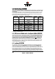
/ + +RVW W ' 'ULYH H 77\SHV V LLQ Q 5 5$,'<1( The following summary gives you an overview of all Host Drive types you can create with the GDT firmware. The ICP Controller can simultaneously control several Host Drives of most various types.
Controller firmware (which are the same for both firmware versions: Standard and RAIDYNE). For the user's convenience the GDTSETUP program is available in two different variants: GDTSETUP loaded from the ICP Controller's Flash-RAM after switching on the computer GDTSETUP loaded from disk under MS-DOS.
/ ([SUHVV 6HWXS This function allows the easy setup of Array Drives and does not require any previous knowledge. If you choose this function, GDTSETUP carries out the complete installation entirely on its own, giving you, for example, a fully operational RAID 5 Array Drive with optimized settings (for instance, with all SCSI features of a given drive activated). After selecting Configure Host Drives and Create new Host Drive, GDTSETUP scans the system for ICP Controllers and "free" hard disks (i.e.
Select with the bar the hard disks you want to integrate into the new Host Drive. Depending on the number of selected drives in the Choose Type windows all possible Host Drive configurations are high-lighted.
Press . You may select the desired Host Drive type. In our example select RAID5 and press . That's it! As you can see from the next picture, the RAID5 Array Drive has been fully automatically configured. It is in the build state.
Press several times to get detailed information on the Array Drive's configuration and components. Press several times to leave GDTSETUP. A new screen comes up giving you detailed progress information on the build process.
As you can see, the build process for the 4GB Array Drive takes approximately 22 minutes. If you press GDTSETUP warns you that the array is not yet redundant. Pressing again brings up the following screen, telling you the system needs a reboot to recognize the new Host Drive(s).
/ 6HOHFW &RQWUROOHU If there are more GDT RP Series controllers in the PCI computer, Select Controller lets you select the controller where you can apply all of the following GDTSETUP choices to. The currently selected controller is displayed on the lower left side of the screen. Below "Position", the PCI Slot number is displayed. The available features of the ICP Controller depend on the firmware installed.
/ &RQILJXUH &RQWUROOHU After pressing and the Advanced Setup allows to select the Configure Controller menu option. Press .
/ &&RQWUROO OOHHU U 66HWW WWLLQJV (To change a setting, move the cursor keys n and p to the field and press . Note: In order to obtain the full performance of your ICP Controller, it is very important that the Delayed Write function is 2Q, too. If you find a different setting, we recommend changing it now.
1. Get the latest GDT_RPFW file for the ICP Controller (download it from our BBS, or our Website, or ask for an upgrade disk if you do not have a modem). The file does NOT need to be expanded ! 2. Format a 3.5" HD disk (1.44MB) and copy the GDT_RPFW file on this disk. 3. After loading GDTSETUP (from Flash-RAM or from disk under MS-DOS) select the desired ICP Controller for the firmware update and press the -key to enter the Advanced Setup. 4.
The new versions of the GDT Firmware, the BIOS and GDTSETUP are available after the next cold-boot. / ,,QWHOOL OOLJJHQW W ))DXOW W % %XV The GDT RP Series Controllers support two types of intelligent subsystems: 1. Subsystem which are accessed via the Intelligent Fault Bus (IFB, which is similar to the DEC™ fault bus). E.g. Storage Works ™. The IFB is based on an asynchronous bus on the SCSI connector and requires appropriate hard/software in the subsystem. 2.
3. Messaging of the states of the intelligent subsystems temperature, power supply condition, fan speed etc. to the GDT RP Series controller. Of course the intelligent subsystem must be designed to implement all these features. The key point is the communication between the subsystem and the GDT RP Series controller. Some subsystems seem to have a lot of LEDs, redundant power supplies, etc., but are not intelligent at all. They stand there and keep all information for themselves.
The GDT RP Series controllers support in the standard delivery the Intelligent Fault Bus (IFB) on channel A. The Fault Bus Module is a small PCB which plugs as a daughter board onto the main PCB of the GDT RP Series controller. Once it is installed, all further channels are also IFB equipped. This screen shows you the states of the Fault Bus and the description of the LED blinkcodes.
With the Perform LED Tests menu, you can check if the LEDs and blink-codes are properly controlled and displayed. / &RQILJXUH 3K\VLFDO 'HYLFHV This menu allows you to prepare hard disks and removable hard disks for use with the ICP Controller (hierarchy level 1). You can scan the SCSI bus again for a given SCSI-ID (this may become necessary when another SCSI device is being connected during the operating session).
This screen tells you: - the SCSI channel - which SCSI-ID a drive has (the entry SCSI I/O processor stands for the according SCSI channel of the ICP Controller. Its default setting is ID 7, as explained in chapter B) - the state of initialization ("i" = initialized) - the SCSI names of the drives - the state, [RW] = Read + Write, [RO] = Read only, [RM] = Removable - the gross capacity - if component of a Logical Drive Use the cursor keys n and p to highlight the drive you wish to initialize.
You may select the high-lighted menu options. The other options are either not appropriate to the type of device (removable hard disk), or currently blocked because of security reasons (e.g., the drive belongs to an Array Drive) / 66&6, , 3 3DUDPHWHU U ,,QLWLDOL OL]]H This option can destroy all data on the hard disk. If a hard disk is not yet initialized, you have to initialize it first.
6\QF 7UDQVIHU (QDEOHG 'LVDEOHG The SCSI-bus knows two methods of data transfer: asynchronous and synchronous transfer. Each SCSI device must be able to perform the first type of transfer, the second one is optional. The advantage of the synchronous transfer consists in a higher data transfer rate, since the signal transfer times on the possibly long SCSI-cable have no influence on the transfer rate anymore.
The warning of the destruction of all data implies different evaluations, depending on the device's current state and the options you selected: 1. First Initialization of the SCSI Device In this case, the warning must be taken seriously. If the drive was previously connected to a different controller (e.g. NCR etc.) and still contains important data, this data will be lost now. 2.
/ &&KHFN N 66XUIDFH This option destroys all data on the hard disk. This option allows the checking of the surfaces of the hard disk media. The GDT RP Series Controller writes and reads certain data patterns and checks them for correctness. After confirming the security request, a progress information is displayed. You can interrupt the Check Surface option by pressing .
/ 9 9LHZ Z ' 'HIHFWV 66WDWXV This option allows you to check the number of media defects the selected hard disk has. Grown defects. Number of media defects that have occurred in addition to the media defects the hard disk already had upon delivery. Primary defects. Number of media defects that the hard disk already had upon delivery.
Last status: The Last Status gives detailed information on the last failure of a hard disk. The information is only present until the next hard reset of the system and may help for deeper failure analysis or tracing. The following listed messages are part of the SCSI documentation. Format: ["""" \] (???? = additional device specific messages) ["""" K NO SENSE. Indicates that there is no specific sense key information to be reported for the designated logical unit.
["""" K BLANK CHECK. Indicates that a write-once device or a sequential access device encountered blank medium or format-defined end-of-data indication while reading or a write-once device encountered a nonblank medium while writing. ["""" K VENDOR-SPECIFIC. This sense key is available for reporting vendor specific conditions. ["""" $K COPY ABORTED.
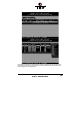
The next page shows a block diagram of a SAF-TE subsystem.
&KDSWHU / *'7 8VHU V 0DQXDO
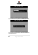
After selecting the SEP press . You can either configure the SAF-TE Slots (i.e., the drive bays in the subsystem), or view the enclosure's status. With the -bar you can assign hard disks to a SAF-TE slot. Once you have finished the assignment press to save the new configuration.
In this example 2 of the 4 available slots in the subsystem are occupied with hard disks. The following screen shows you the enclosure's status. Features which are marked with (Not available) are not implemented in the subsystem/SEP.
/ &RQILJXUH /RJLFDO 'ULYHV Logical Drives (hierarchy level 2) are installed in this main menu option. Selecting Configure Logical Drives leads you to the screen shown next. As you can see, there is already one Logical Drive in the list. The drive's name has been assigned automatically and contains the channel description and the SCSI-ID after the underscore ("_"). This can serve as a reminder when you install a complex system with many drives (naturally you can change the name).
Change Drive Name. Here you can enter a name for the selected drive. Remove Drive. This menu option lets you remove a single Logical Drive from the list of available Logical Drives. (Note: Logical Drives belonging to a RAID 0, 1, 4, 5 or 10 Host Drive cannot be removed. To do so, the corresponding Host Drive has to be removed first.) Unload Drive. Unlock the media of the removable hard disk, which belongs to the Logical Drive.
/ ,,QVWDOOL OOLQQJ J D D //RJLFDO O ' 'ULYH H RRI I WWKH H 77\SH H ' 'LVN Mark the selected SCSI device with the -bar (pressing the -bar again undoes your choice) and confirm your choice with . A security request appears. If you confirm with , GDTSETUP allows you to limit the size of the Logical Drive.
spare hard disks in the future. It would be bad luck if the new hard disk would have 2060MB, only. It simply wouldn't fit into the Array Drive. If you limit the capacity to e.g., 2000MB from the beginning, you can be sure that all future 2GB hard disk will have at least 2000MB and thus can be used as spare hard disk. After pressing the list appears again, but with a new entry. The -key shows the hard disk forming the new Logical Drive.
/ ,,QVWDOOL OOLQQJ J D D //RJLFDO O ' 'ULYH H RRI I WWKH H 77\SH H &&KDLQ In some literature Disk Chaining is also called Disk Spanning. You can picture the functioning mechanism of a type Chain Logical Drive as follows: all SCSI devices forming the Logical Drive are linked together one by one in the exact same order in which they have been selected with the -bar. This concatenation can be compared with a chain.
After pressing the list appears again, but with a new entry. The -key shows the hard disk forming the new Logical Drive.
/ &RQILJXUH $UUD\ 'ULYHV This main menu option allows you to configure Array Drives (level of hierarchy 3). Array Drives with the following listed RAID levels can be configured within this menu. RAID 0 pure data striping without redundancy RAID 1 disk mirroring RAID 4 data striping with dedicated parity drive RAID 5 data striping with striped parity RAID 10 RAID 0 combined with RAID 1 The ICP Controller can manage up to 35 Array Drives (with different RAID levels) simultaneously.
Move the selection-bar to the second entry and select Logical Drives No. 1,2 and 3. The "M" means Master. For a striping array (RAID 0, 4, 5, 10), this is the first Logical Drive in the array. For a RAID 1 (mirroring) array this is the Logical Drive which contains the valid data and which should be copied to the second Logical Drive. After pressing GDTSETUP displays a list of possible RAID levels. The number of previously selected Logical Drives determines the high-lighted levels.
For this example we select RAID-5 and press . This security request has to be taken seriously. If you confirm with all data are lost. GDTSETUP will ask you for the Stripe Size. This is the size of the stripes into which the data is divided. Valid values are 16KB, 32KB, 64KB or 128KB. The default is 32KB which we leave for this example and therefore press . (Note: 32KB stripe size is suggested because in various performance tests it has proved to be the best value.).
If necessary you can limit the Array Drive's capacity. For this example we take the complete capacity. The Array Drive has entered the build state, i.e., the parity information is currently generated.
After completion of the build process, the Array Drive's state is ready, i.e., fault tolerant.
/ 1 1RWHV V RRQ Q WWKH H &&RQILJXUDWLRQ Q RRI I 5 5$,' ' D DQG G $ $UU UUD D\V V ' 'ULYHV (1) Use preferably Logical Drives of the type disk to build an Array Drive. Of course, RAID Array Drives can be configured with Logical Drives of the type chain, too, but the aspects of security should be taken into consideration as well. For regular RAID Array Drives, type disk Logical Drives are used.
Ready state. The disk array is fully operational when in the ready state. All redundant information is present, that is, a hard disk can fail without impairing the functionality of the disk array. This is the normal state of a disk array. The state ready/expand indicates that the RAID level and/or capacity are currently migrated/expanded. Fail state. The Array Drive changes to the fail state whenever a Logical Drive fails.
/ &&KDQJH H ' 'ULYH H 1 1DPH This command allows you to change the name of an Array Drive. The name serves to identify an Array Drive in GDTSETUP. This can be very helpful for configurations where several Host Drives of various types are operated by a single controller. / (([SDQG G $ $UU UUD D\ \ ' 'ULYH The Expand Array Drive option, which is also available online within GDTMON, includes two functions: 1.
GDTSETUP displays a list with Logical Drives which are free and can be added to the existing Array Drive. Here we select the first Logical Drive. We could have also added the first and the second Logical Drive to expand the Array Drive's capacity in one step from 400MB to 800MB.
After the acknowledgement of the security request, the expansion process starts. After completion of this process the new capacity is displayed. It is added as another Host Drive (see next pages).
/ $ $GG GG 5 5$,' &&RPSRQHQW In certain "emergency" cases this is a very powerful and helpful option. This function allows you to add to a Logical Drive which is member of an Array Drive, another Logical Drive as a mirror drive (RAID-1). Example: You have configured an Array Drive with 4 Logical Drives. One Logical Drive has failed and the Array Drive went into the fail state. Another failure would cause data loss.
In this example the Array Drive is ready. Here you can select the RAID-1 Master. This is the Logical Drive which data are mirrored to the new Logical Drive. Logical Drive DISK_C4 is added as a RAID-1 component to DISK_A6.
Press to get detailed information of the Array Drive. If you think this flexibility through to the end, you could add another RAID-1 Logical Drive to each Logical Drive which is component of a RAID 4/5 Array Drive (double redundancy, but also double cost).
because the Array Drive is without redundancy. The replacement Logical Drive has to have at least the same capacity as the failed one. The replacement is carried out either interactively with GDTSETUP or online with the GDTMON utility program (see Chapter K). Before you replace the failed Logical Drive, you have to power off the computer system. Then, after having installed the replacement hard disk as a new Logical Drive, you can add it to the Array Drive.
/ 5 5HPRYH H 5 5$,' &&RPSRQHQW This option corresponds with the Add RAID-1 Component option. It allows you to remove a previously configured RAID-1 combination. Press to get details. As you can see, all Logical Drives have the type Disk, again.
/ 5 5HPRYH H $ $UU UUD D\ \ ' 'ULYH This command allows you to remove an existing Array Drive. All the data of the Array Drive will be lost ! Before you confirm the security request with , you should be sure about this choice.
the Array Drive, that is the Host Drives, have not been modified in any kind whatsoever in the meantime. / $ $GG GG + +RW W ))L[ [ ' 'ULYH This submenu option allows you to add a Hot Fix drive to an existing RAID 1, RAID 4, RAID 5, or RAID 10 Array Drive. There are two different types of Hot Fix drives: Private and Pool Hot Fix drives. A Pool Hot Fix Drive is a spare drive within the so-called Hot Fix Pool. A drive in a Hot Fix Pool is available for several Array Drives as a Hot Fix drive.
Example of an Array Drive configuration with a Hot Fix drive (press the -key to display the following screen). The Array Drive configuration sheet, shows the active Array Drive members including the Pool Hot Fix drive.
/ 5 5HPRYH H + +RW W ))L[ [ ' 'ULYH This option allows you to remove a Hot Fix Drive from an existing Array Drive. Naturally, the Hot Fix drive must not be used up so far. / + +RW W ))L[ [ 3 3RR RRO O $ $FF FFHHVV By selecting the Hot Fix Pool Access option, the access of a specific Array Drive to the Hot Fix pool can be enabled of disabled.
/ % %XLO LOG G 5HEXLO LOG G 3 3URJUHVV Whenever an Array Drive is in the build or rebuild state, you can select this option, to get progress information and estimates for the required time.
/ &RQILJXUH +RVW 'ULYHV This main menu option allows you to configure Host Drives (level of hierarchy 4). As already mentioned before, these are the drives the Host Computer is aware of. Host Drives can consist of a single hard disk, or of many hard disk combined to a RAID 5 Array Drive. As you can see from the following screen, there are two Host Drives in the list, which belong to the same physical Array Drive. Host Drive 4 (2 of 2) is the result of a previous capacity expansion.
/ &&KDQJH H ' 'ULYH H 1 1DPH This command allows you to change the name of a Host Drive. The name serves to identify a Host Drive with GDTSETUP.
/ 66ZDS S + +RVW W ' 'ULYHV When the PCI computer is switched on, the Host Drives are initialized in the order of the Host Drive list, which means that the operating system is booted from the Host Drive having the lowest number. For reasons of flexibility, a Host Drive's position in the list can be changed.
/ 5 5HPRYH H + +RVW W ' 'ULYH Removing a Host Drive is a serious action. All data will be lost after removal. If you want to remove a Host Drive belonging to an Array Drive for which several Host Drives exist (after capacity expansion, or after splitting), all other Host Drives will also be removed.
/ 66SOL OLW W + +RVW W ' 'ULYH For some purposes it might of interest to split an existing Host Drive into two or several Host Drives. Each Host Drives looks to the operating system just like a single hard disk. Since the new Host Drives have smaller capacities GDTSETUP has to write new header information on the two Host Drives. All data will be lost.
/ 0 0HUJH H + +RVW W ' 'ULYHV This function reverses the Split Host Drive option. Only such Host Drives can be merged which belong to the same Array Drive or Logical Drive. Since the new Host Drives has a larger capacity GDTSETUP has to write a new header information on the new Host Drives. All data will be lost.
/ 3 3DUWLWLRQ Q + +RVW W ' 'ULYH This option is not available, when loading GDTSETUP from the Flash-RAM of the controller. Before you can partition a new Host Drive it may become necessary to reboot the system, first. The partitioning menu has similar functions as the MS-DOS program FDISK. You can create and delete a partition and also change the active partition. MS-DOS can only be booted from an active partition.
This page is intentionally left blank.