8VHU V 0DQXDO ,&3 &RQWUROOHUV RI WKH *'7 5' 6HULHV 3&, :LGH 8OWUD 6&6, 5$,' &RQWUROOHUV VW (GLWLRQ &RS\ULJKW ,&3 YRUWH[ &RUSRUDWLRQ :HVW 9DQ %XUHQ 6WUHHW 3KRHQL[ $= 86$ ,&3 YRUWH[ &RPSXWHUV\VWHPH *PE+ )DOWHUVWUDVVH )OHLQ *HUPDQ\ $OO 5LJKWV DQG &KDQJHV 5HVHUYHG
&RQWHQWV V 2 2YHUYLHZ 3DUW W ,, &KDSWHU $ &KDSWHU % &KDSWHU & *HQHUDO ,QIRUPDWLRQ +DUGZDUH ,QVWDOODWLRQ 4XLFN 6HWXS 3DUW W ,,,, &KDSWHU ' &KDSWHU ( &KDSWHU ) 8VLQJ 0LFURVRIW 06 '26 :LQGRZV [ 8VLQJ 1RYHOO 1HW:DUH 8VLQJ :LQGRZV 17 3DUW W ,,, ,,, &KDSWHU * &KDSWHU + 7KH *'7021 3URJUDP $SSHQGL[ The following chapters are part of a PDF-document which is located in a corresponding directory on the ICP System CDROM: 8VLQJ ,%0 26 Y [ 8VLQJ 6&2 81,; 9 8VLQJ ,QWHUDFWLYH 81,; 8VLQJ 8QL
/LPLWHG G : :DUU UUD DQW\ ,&3 YRUWH[ &RUSRUDWLRQ ,&3 YRUWH[ JXDUDQWHHV WKDW WKLV SURGXFW LV IUHH IURP GHIHFWV LQ PDWHULDO DQG ZRUNPDQVKLS 6XEMHFW WR WKH FRQGLWLRQV DQG OLPLWDWLRQV VHW IRUWK EHORZ ,&3 YRUWH[ ZLOO DW LWV RZQ RSWLRQ HLWKHU UHSDLU RU UHSODFH DQ\ SDUW RI WKLV SURGXFW ZKLFK SURYHV WR EH GHIHFWLYH E\ UHDVRQV RI LPSURSHU ZRUNPDQVKLS RU PDWHULDOV 3DUWV XVHG WR UHSDLU SURGXFWV RU UHSODFHPHQW SUR GXFWV ZLOO EH SURYLGHG E\ ,&3 YRUWH[ RQ DQ H[FKDQJH EDVLV DQG ZLOO EH HLWKHU QHZ RU UHIXUELV
3LFN XS WKH SKRQH LI \RX QHHG WHFKQLFDO VXSSRUW DQG GLDO WKH QXPEHUV )RU (XURSH )RU WKH 86$ RU VHQG XV D )$; )RU (XURSH )RU WKH 86$ RU VHQG XV DQ ( 0DLO )RU (XURSH VXSSRUW#YRUWH[ GH )RU WKH 86$ VXSSRUW#LFS YRUWH[ FRP RU FDOO RXU %%6 1 K RU FKHFN RXU :HEVLWH KWWS ZZZ LFS YRUWH[ FRP
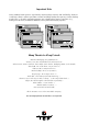
Important Note Using modern RAID Systems significantly increases data security and availability. Under no circumstances does it relieve you from a careful and daily backup on tape or a similar backup media. This is the only method to protect your valuable data against total loss (e.g., through fire or theft), accidental deletion, or any other destroying impacts.
)&& & && &R RPSOLOLD DQFH 6WDWHPHQW ,QIRUPDWLRQ IRU WKH 8VHU 127( 7KLV HTXLSPHQW KDV EHHQ WHVWHG DQG IRXQG WR FRPSO\ ZLWK WKH OLPLWV IRU D &ODVV % GLJLWDO GHYLFH SXUVXDQW WR 3DUW RI WKH )&& 5XOHV 7KHVH OLPLWV DUH GHVLJQHG WR SURYLGH UHDVRQDEOH SURWHFWLRQ DJDLQVW KDUPIXO LQWHUIHUHQFH LQ UHVLGHQWLDO LQVWDOODWLRQV 7KLV HTXLS PHQW JHQHUDWHV XVHV DQG FDQ UDGLDWH UDGLR IUHTXHQF\ HQHUJ\ DQG LI QRW LQVWDOOHG DQG XVHG LQ DFFRUGDQFH ZLWK WKH LQVWUXFWLRQV PD\ FDXVH KDUPIXO LQWHUIHUHQFH WR UDGLR FRPPXQLF
7DEOH RI &RQWHQWV $ ,1752'8&7,21 $ 3URGXFW ,GHQWLILFDWLRQ $ .
% 6ZLWFKLQJ 2Q WKH 3&, &RPSXWHU 6\VWHP % 7URXEOH 6KRRWLQJ % &KHFNLQJ WKH ,&3 &RQWUROOHU &RQILJXUDWLRQ % /RDGLQJ *'76(783 % 8SGDWLQJ WKH ,&3 &RQWUROOHU :LWK 1HZ )LUPZDUH % $GGLWLRQDO 1RWHV
' 8VLQJ :LQGRZV [ ' 8VLQJ D &' 520 'ULYH XQGHU 06 '26 RU :LQGRZV [ ' ([DPSOH 8VLQJ WKH $6: 6RIWZDUH IRU WKH &' 520 ' ([DPSOH 8VLQJ FRUHO6&6, IRU WKH &' 520 ' 7KH *'7 $63, 0DQDJHU *'7$63, (;( ' 8VLQJ $6: $63,',6.
) ,QVWDOODWLRQ DQG 8SJUDGH RI :LQGRZV 17 [ [ ) $GGLQJ $GGLWLRQDO &DSDFLW\ $IWHU $Q 2QOLQH ([SDQVLRQ * 7+( ',$*126,6 352*5$0 *'7021 * /RDGLQJ *'7021 * /RDGLQJ WKH *'7021 3URJUDP 8QGHU 1HW:DUH * /RDGLQJ WKH *'7021 3URJUDP 8QGHU 26 * /RDGLQJ WKH *'
&KDSWHU $ *HQHUDO ,QIRUPDWLRQ
$ ,QWURGXFWLRQ *'7 5' 6HULHV 3&, +DUGZDUH 5$,' 'LVN $UUD\ &RQWUROOHUV ZLWK RU :LGH 8OWUD 6&6, &KDQQHOV DQG RQH 1DUURZ 8OWUD 6&6, &KDQQHO In order to take full advantage of modern operating systems, high performance computer systems are needed. When assessing the performance of a computer system, the aspects speed and security of the mass-storage subsystem are gaining increasing importance.
$ .H\ )HDWXUHV RI WKH ,&3 &RQWUROOHUV RI WKH *'7 5' 6HULHV Hardware RAID Controllers with RAID 0, RAID 1, RAID 4, RAID 5 and RAID 10 Array Drives at controller level, completely independent of the computer system and the operating system. Several Array Drives can be operated simultaneously. "Private" (i.e., for one Array Drive) or "Pool" (i.e., for several Array Drives) Hot Fix Drives. Online Capacity Expansion.
$ &RS\ULJKWV 3DWHQWV Parts of the ICP GDT RD Series controllers are protected under international copyright laws and agreements. No part of the product or the manual, or parts of the manual may be reproduced in any form, physical, electronic, photographic, or otherwise, without the expressed written consent of ICP vortex Computersysteme GmbH. For this product a patent is registered at the Deutsches Patentamt in Munich with the official reference no. 4121974.
$ 6RIWZDUH /LFHQVH $JUHHPHQW Please read this Software License Agreement before opening the CD/disk packaging and before starting to use the programs. Each loading of a program covered by this license agreement, each transmission within any existing network to another computer, as well as each copy on a mass storage system, regardless of what kind (floppy disk, hard disk,CD, MO, etc.), represents a duplication of the program according to copyright regulations.
$ *HQHUDO ,QIRUPDWLRQ The ICP Controller should be installed by an authorized ICP vortex distributor. Precondition for the safe installation is an anti-static work place (earthed mat on the table with wrist bands connected to an earth). ICP vortex does not take any responsibility for damage arising out of improper installation. This manual contains all the information available at the time it was written. Errors and/or incomplete information are possible.
$ 3URGXFW 'HVFULSWLRQ $ ,QWHO L 5' , 2 3URFHVVRU The i960RD I/O processor is a member of a new RISC CPU generation which was specifically designed for I/O applications. This CPU on an ICP Controller can reach a performance of 40 MIPS and supervises all tasks of the Fibre Channel / SCSI devices, the RAID controlling and the communication with the PCI computer. In doing so, it significantly offloads the PCI computer, leaving it free to perform its original tasks.
$ ,&3 &RQWUROOHU )LUPZDUH 3&, %,26 DQG *'76(783 The firmware, the BIOS of the ICP Controller and the configuration program GDTSETUP are stored in a Flash-RAM on the ICP Controller PCB. The firmware is designed for parallel processing and it controls all resources of the ICP Controller. This means that the entire administration of SCSI devices and RAID is exclusively carried out by the ICP Controller. Thus, the host is significantly offloaded.
$ 2SHUDWLQJ 6\VWHP 'ULYHU 6RIWZDUH Drivers for the following operating systems are available: 2SHUDWLQJ 6\VWHP MS-DOS 3.3 to 6.x Novell NetWare 3.11, 3.12, 4.x SCO UNIX System V/386 3.2v5.x Interactive UNIX V/386 3.2v3, 3.2v4 SCO UnixWare 2.x IBM OS/2 2.x, Warp 3, Warp 4 Windows NT 3.5x, 4.x Windows 95 Linux 1.2.13, 1.3.37, 1.3.97, 2.0.00, 2.0.
*'7 5' 2YHUDOO 9LHZ
*'7 5' 2YHUDOO 9LHZ
*'7 5' 2YHUDOO 9LHZ
*'7 5' 2YHUDOO 9LHZ
*'7 5' 2YHUDOO 9LHZ
*'7 5' 2YHUDOO 9LHZ
&KDSWHU % +DUGZDUH ,QVWDOOOOD DWLRQ
% +DUGZDUH ,QVWDOODWLRQ % %HIRUH ,QVWDOODWLRQ The ICP Controller is designed for minimum power consumption and maximum operational security. It therefore contains delicate electrical components (CMOS).
Recommended SIMM Manufacturers SIMMs from Goldstar, Motorola, NEC, Samsung, Siemens, Texas Instruments, and Toshiba have been successfully tested with the ICP Controllers. This recommendation does not imply an evaluation of quality. SIMMs from other manufacturers may be equally suitable. You can use single- and double-sided SIMMs. When using double-sided SIMMs with high power consumption special care should be taken that both, the ICP Controller and SIMM are properly cooled.
% 6&6, %DVLFV Whoever has been involved with the subject of SCSI will have noticed that the "Small Computer System Interface" is an extremely interesting technology, which has become widely accepted in comparison to other interface models and has constantly adapted to the needs of customers. This builds up confidence and (investment) security. Last but not least, SCSI has remained the de facto I/O interface for smaller to mid-sized mass storage systems in the field of business.
In LVDS-Mode, an SE signal wire and its associated SE ground wire (GND) build a differential pair. Therefore, please take care when choosing an external round cable. It has to be explicitly designed for LVDS. Very often all GND wires are put together in the connector. These kinds of cables must not be used for LVDS. 80MB/sec.
16 Bit, wide 16 Bit, wide 16 Bit, wide Fast Fast-20, Ultra Fast-40, Ultra2 SE SE LVDS 20 MB/sec. 40 MB/sec. 80 MB/sec. 15 4 15 2.0 meters 1.5 meters 12 meters In addition to specifications mentioned above, the following should be kept in mind when selecting and installing SCSI cables: Always install SCSI cables that are as short as possible. The lengths in the table above are absolute maximum lengths. (Total length of internal and external cables per channel).
([DPSOH IRU D 6&6, )ODW 5LEERQ &DEOH IRU %LW 6&6, 'HYLFHV QDUURZ
([DPSOH IRU D 6&6, )ODW 5LEERQ &DEOH IRU %LW 6&6, 'HYLFHV ZLGH
([DPSOH IRU H[WHUQDO :LGH 8OWUD FDEOHV 0HWHUV DQG 0HWHUV
% 6&6, 7HUPLQDWLRQ In order to ensure a flawless and interference-free signal transmission on the SCSI bus and to minimize the detrimental effects of external noise generators, both ends of the SCSI cable have to be terminated. The SCSI specification prescribes different termination methods for SE and LVDS SCSI bus systems. There are two alternative termination modes for Single-Ended SCSI bus systems: The passive termination and the active termination, also known as Alternative-2 termination.
*'7 5' *'7 5' *'7 5' *'7 5' *'7 5' Valid connections and required GDTSETUP settings for the Wide/Ultra2 SCSI Channels.
*'7 5' Valid connections and required GDTSETUP settings for the Wide/Ultra2 SCSI Channels A, B and C. External UHD Connector, 68 pin Internal 68 pin Connector Termination Occupied and end terminated Occupied and end terminated Not occupied Not occupied Not occupied Occupied and end terminated Not occupied Occupied and end terminated Not occupied Occupied and both ends terminated, i.e.
% ,&3 6&6, $FFHVVRULHV Order # Part Name 8840 Fast-SCSI Bracket 8841 Wide-SCSI Adapter 8842 Wide-SCSI Bracket 8843 Wide/Ultra Flat Ribbon Cable Narrow-Wide Bracket 8846 8951 LVDS/SE Terminator 8952 LVDS/SE Terminator for SE/LVDS Hard Disks with SCA Connector. Description External SCSI connector with an internal 50 pin header and an external 50 pin HD SCSI connector (female). 16 Bit to 8 Bit SCSI adapter with a 50 pin header and a 68 pin HD SCSI connector (male).
/9'6 6( 7HUPLQDWRU IRU SLQ 6( RU /9'6 FDEOH
/9'6 6( 7HUPLQDWRU IRU 6( /9'6 +DUG 'LVNV ZLWK 6&$ &RQQHFWRU
% ([DPSOHV On the following pages, are some examples of correct SCSI cabling. First of all a few general tips: The ICP firmware always assigns the Narrow/Ultra SCSI Channel as the last channel number. I.e., ICP Controller GDT6118RD GDT6518RD GDT6128RD GDT6528RD GDT6538RD GDT6558RD Wide/Ultra2 SCSI Channels A Narrow/Ultra SCSI Channel B A, B C A, B, C A, B, C, D, E D F SE-devices (e.g., Ultra SCSI hard disks, CD-ROM drives, DAT drives, Scanners, Printers, DLT drives, etc.
2QH LQWHUQDO :LGH 8OWUD 6&6, +DUG 'LVN
6HYHUDO LQWHUQDO :LGH 8OWUD 6&6, +DUG 'LVNV
,QWHUQDO DQG H[WHUQDO :LGH 8OWUD 6&6, +DUG 'LVNV
,QWHUQDO DQG H[WHUQDO :LGH 8OWUD 6&6, +DUG 'LVNV DQG 6( 'HYLFHV
,QYDOLG &RQILJXUDWLRQ
% ,QVWDOOLQJ WKH ,&3 &RQWUROOHU Make sure that the ICP Controller is equipped with an appropriate SIMM. As already mentioned it is not possible to operate the ICP Controller without a SIMM. Step 1 Switch off the PCI computer system and remove all cables (first of all the power supply). Step 2 Following the instructions in the computer manual, open the case of the PCI computer, so that you have easy access to the PCI expansion slots.
Step 7 If required, you can connect the HDD-front-LEDs of the PCI computer system to the LED connectors of the ICP Controller.
1. The PCI computer system must automatically assign (map) the ICP Controller BIOS to an adequate address in the lower, 1MB area of the computer system’s main memory. 2. The PCI computer system must map the ICP Controller’s Dual Ported Memory (needed for high performance operation) to an adequate address in the lower, 1MB area of the computer system’s main memory. In addition, it has to disable the shadowing of this address . 3. Assigning a system IRQ to a PCI interrupt. The PCI 2.
The GDT boot message appears. In the following example, a GDT6518RD Controller has been detected in PCI slot 3, and it has 16MB of RAM ("16 MB RAM detected..".). On the Wide/Ultra2 SCSI channel three Ultra2 Quantum hard disks have been recognized, and, on the Narrow/Ultra SCSI channel B, a DLT2000XT streamer and a NEC CDROM drive.
*'7 5' +:/ 0% 5$0 N% N% )ODVK 5$0 *'7 5' +:/ stands for the type of ICP Controller found by the GDT BIOS. HWL means Hardware level. 0% 5$0 indicates that the installed SIMM is a 16MB, non-parity Fast Page Mode (FPM) SIMM. Depending on the type and size of the installed SIMM the following messages are possible (xx = 4, 8, 16, 32, 64, 128): [[ 0% 5$0 [[ 0% 5$0 3 [[ 0% ('2 5$0 [[ 0% ('2 5$0 3 xx MB Fast Page Mode (FPM) SIMM without parity (i.e.
you might have to disable the shadowing manually in the system-BIOS setup program. In addition, make sure that this address space is not used by another expansion card. (This is a work-around, not a solution. PCI 2.x is a well defined specification, and a fully compatible system-BIOS should have assigned the DPMEM automatically.
Loading GDTSETUP under MS-DOS becomes necessary, when you want to use GDTSETUP's integrated partitioning functions, or when you have totally disabled the GDT's BIOS (which includes the GDTSETUP variant loadable from FLASH-RAM). If you want to load GDTSETUP under MS-DOS you have to load the device driver GDTX000 first. This can be done in two ways: 1. Starting the device driver from the DOS-command level by typing GDTX000 2. Starting the device driver automatically by means of the CONFIG.
Press the -key for the Advanced Setup. Select Configure Controller and press .
The fields can be selected by moving the cursor keys Ç and È . The values can be changed by pressing and selecting a new setting. Leave this menu by pressing the key. In order obtain optimum performance from your ICP Controller, it is essential that the Cache and the Delayed Write options of the ICP Controller are set 21, too. If you should find different settings here, we recommend that they be changed now.
5. The update process starts as soon as the desired GDT_RPFW file has been selected. Strictly observe the messages and instructions of GDTSETUP. It is extremely important that the system is not switched off or reset during the update process. It is very likely that this would cause the ICP Controller to become inoperable. The new versions of the GDT Firmware, the BIOS and GDTSETUP are available after the next cold-boot.
% $GGLWLRQDO 1RWHV Before the computer is switched off or a hard reset is carried out, the ICP Controller first has to write the current contents of its cache RAM back to the hard disk(s) (flush). The computer may only be switched off or reset after all hard disk accesses have been completed.
&KDSWHU & 4XLFN 6HWXS
& 4XLFN 6HWXS & :KDW LV WKH $LP RI 4XLFN 6HWXS " In the previous chapter we installed the ICP Controller in a PCI computer and connected the SCSI devices. Now these SCSI devices must be prepared in order to run with your operating system. This Quick-Setup chapter should help you to get started quickly.
Before we go through these examples step by step, we would like to explain a few terms and relations important for the basic understanding of the ICP Controller firmware. At the end of example 4, we will try to answer the three questions above. & :KDW LV WKH ,&3 &RQWUROOHU )LUPZDUH " We refer to firmware as the operating system which controls the ICP Controller with all its functions and capabilities.
& 7KH 'LIIHUHQW 5$,' /HYHOV 5$,' 'DWD 6WULSLQJ According to the adjusted stripe size (e.g., 16 KB) and the number of hard disks, the data blocks are split into stripes. Each stripe is stored on a separate hard disk. Especially with sequential read and write operations, we can observe a significant improvement of the data throughput. RAID 0 includes no redundancy at all, i.e., when one hard disk fails, all data is lost.
5$,' 'DWD 6WULSLQJ :LWK D 'HGLFDWHG 3DULW\ 'ULYH RAID 4 works in the same way as RAID 0. The data are striped amongst the hard disks. Additionally, the controller calculates redundancy data (parity information) which are stored on a separate hard disk (P1, P2, ...). Even when one hard disk fails, all data are still fully available. The missing data is recalculated from the data still available and the parity information.
5$,' &RPELQDWLRQ RI 5$,' DQG 5$,' The idea behind RAID 10 is simply based on the combination of RAID 0 (Performance) and RAID 1 (Data Security). Unlike RAID 4 and RAID 5, there is no need to calculate parity information. RAID 10 disk arrays offer good performance and data security. As in RAID 0, optimum performance is achieved in highly sequential load situations. Identical to RAID 1, 50% of the installed capacity is lost for redundancy.
& 7KH ([SUHVV 6HWXS )XQFWLRQ RI *'76(783 Whenever you load GDTSETUP and select the desired ICP Controller, it comes up in its EXPRESS Setup mode. This mode does not require any previous knowledge. If you choose this function, GDTSETUP carries out the complete installation entirely on its own, providing you for example with a fully operational RAID 5 Array Drive with optimized settings (for instance, with all SCSI features of a given drive activated).
Host Drives). Use the -bar to select the desired hard disks (they are marked with an "*"). On the right side GDTSETUP offers highlighted the possible configurations with these drives. Pressing ends the selection. After choosing a configuration type for an Array Drive, GDTSETUP displays a security request.
After the confirmation, the Host Drive is automatically built up and configured. After leaving GDTSETUP the parity information is generated. For chapter C, we do not use this function, but give detailed instructions on how to set up a single disk and disk arrays with GDTSETUP and its Enhanced Setup.
& /HYHOV RI +LHUDUFK\ :LWKLQ WKH *'7 )LUPZDUH Both GDT firmware versions (Standard and RAIDYNE) are based on four fundamental levels of hierarchy. Each level has its "own drives" ( = components). The basic rule is: To build up a “drive“ on a given level of hierarchy, the “drives“ of the next lower level of hierarchy are used as components. /HYHO (1) Physical Drives = hard disks, removable hard disks, some MO drives are located on the lowest level.
Within GDTSETUP, each level of hierarchy has its own special menu: /HYHO /HYHO /HYHO /HYHO Ö Ö Ö Ö Menu: Configure Physical Devices Menu: Configure Logical Drives Menu: Configure Array Drives Menu: Configure Host Drives Generally, each installation procedure passes through these 4 menus, starting with level 1. Therefore: First initialize the Physical Drives. Then configure the Logical Drives. Then configure the Array Drives (e.g. Array Drives with RAID 0, 1, 4, 5 and 10).
b.) Load GDTX000 automatically through the CONFIG.SYS file (DEVICE=GDTX000.EXE) Note: GDTSETUP.EXE as well as GDTX000.EXE are on the System Disk - DOS. If GDTSETUP was loaded this way, there is a "D" (Disk) behind the version number. You may now ask what are the differences between the two GDTSETUP variants ? They are small. The GDTSETUP variant loadable from disk under MS-DOS also additionally allows the partitioning of Host Drives, which is not possible with GDTSETUP loaded from the Flash-RAM.
/HYHO /HYHO /HYHO /HYHO 6WHS &RQILJXUH 3K\VLFDO 'HYLFHV Now activate the menu Configure Physical Devices (level 1). A list appears showing all hard disks found on the ICP Controller’s SCSI channels. If you have a ICP Controller with a different number of SCSI channels, the existing SCSI channels are displayed.
(Note: On Channel B, SCSI ID 0, is a drive which has been already initialized before. This is not relevant for our examples). The Configure Disk menu appears which shows various options. For our example we choose the Initialize Disk menu option and press . The parameters within this menu can be changed by pressing and selecting the new setting.
1. Sync. Transfer: Enable The SCSI-bus allows an asynchronous and a synchronous transfer. Every SCSI device must be able to perform the first type of transfer, the second one is optional. The advantage of the synchronous transfer lies in a higher data transfer rate as the signal transfer times on the possibly long SCSI-cable have no influence on the transfer rate anymore. Two SCSI-bus participants wanting to exchange data between each other have to check if and how (i.e.
Press and we are back on the main screen of level 1 and see that the initializationstatus of the SCSI device has changed. 6WHS &RQILJXUH /RJLFDO 'ULYHV We now leave level 1 (by pressing the -key) and are back in the main menu. Now, with the cursor keys n and p select Configure Logical Drives and go to level 2 by pressing .
The main screen of level 2 appears. Move the selection bar to Create new Logical Drive and press . Note: The already existing Logical Drive in this list has no relevance for our example.
Select the initialized hard disk with the -bar (it becomes marked with an "*") and press . For security reasons, you will be asked again if you want to use the selected disk to create a Logical Drive. As we are sure of our choice, we confirm with . GDTSETUP allows you to limit the hard disk size for this Logical Drive. This becomes interesting when you configure disk arrays. For this example we use the full capacity and press .
The dialog box is closed and we are back in the main menu of level 2. As you can see, we have already created a new Logical Drive of the type Disk. The name of the Logical Drive is assigned automatically and contains the channel description and the SCSI-ID after the "_" . This can serve as a reminder when you install a complex system with many drives. (Naturally, you may change the name.) This concludes the installation on level 2. Now press the -key to leave this screen.
Since we have only a single disk assigned to a Logical Drive, there is nothing to do in the Configure Array Drives menu, thus we go directly to the Configure Host Drives menu and have no Step 4. 6WHS &RQILJXUH +RVW 'ULYHV We are now back in the main menu of GDTSETUP and select Configure Host Drive. The main screen of level 4 appears. Press . A list of available Host Drives is displayed. Again, the first entry is not relevant for our example.
We should not forget to mention, that if you would have selected Create new Host Drive, this would have lead you to the same menu as the Express Setup mode. But this example is an exercise which should help you to gain a better understanding of how the ICP Controller and GDTSETUP work. So don't believe we let you do redundant homework. By the way, if you have loaded GDTSETUP from the Flash-RAM () the Partition Drive option will be missing in this menu.
As we are done with the installation and therefore definitely want to leave GDTSETUP, we press any key. IMPORTANT: Always end GDTSETUP by leaving the program in the regular way (do not warm-boot with CTRL-ALT-DEL or cold boot by pressing the RESET button). Certain information is only transferred to the controller when you leave GDTSETUP in the regular way. The Host Drive we have configured in this example is now ready for the installation of the desired operating system.
& ([DPSOH ,QVWDOOLQJ D 0LUURULQJ $UUD\ 5$,' This example is applicable to all ICP Controllers. It is our intention to install a Mirroring Array consisting of two identical hard disks. In the classical terminology of the RAID levels this is called a RAID 1 disk array. We presume that the controller and the SCSI hard disks have been properly installed. Step 1 of the installation is the same as in the first example, therefore we do not explain it again.
Note: The already existing Logical Drive in the first position of this list has no relevance for our example. The second entry was created before. Select the initialized hard disk with the -bar (it becomes marked with an "*") and press .
For security reasons, you will be asked again if you want to use the selected disk to create a Logical Drive. As we are sure of our choice, we confirm with . GDTSETUP allows you to limit the hard disk size for this Logical Drive. This becomes interesting when you configure disk arrays. For this example we use the full capacity and press . The dialog box is closed and we are back in the main menu of level 2.
As you can see, we have created another Logical Drive of the type Disk. The name of the Logical Drive is assigned automatically and contains the channel description and the SCSIID after the "_" . This can serve as a reminder when you install a complex system with many drives. (Naturally, you may change the name.) This concludes the installation on level 2. Now press the -key to leave this screen.
Since we want to create a new Array Drive press . Note: The first entry in this list has no relevance for our example. Move the selection bar to the second entry and press the -bar. The entry is marked with an "M" for Master. This means that the data from this Logical Drive are copied to the second Logical Drive, which we will select next.
Move the selection bar with the cursor key p to the next entry and press the -bar, again. It is marked with an "*"(pressing the -bar again undoes your choice). When the Logical Drive is selected, confirm with . GDTSETUP displays now a list of possible RAID levels, available with the number of Logical Drives selected. In our case it is RAID-0 (data striping) and RAID 1. Move the selection bar to RAID-1 and press .
GDTSETUP displays a security request, which we answer with . As you can easily recognize, we have created a new Array Drive of the Type RAID-1. Its state is build. When we leave GDTSETUP at the end of this example, you will see that the ICP Controller automatically copies the data of the first Logical Drive (our master) to the second Logical Drive. During this synchronization the RAID-1 array is fully operational.
disks, which are connected with different SCSI channels of the ICP Controller, both writeaccesses are performed simultaneously (this method is often called Disk Duplexing). During a read-access of the host computer the data will be read from the Logical Drive whose hard disk has the fastest access to the data requested. If a hard disk should fail (for instance due to a mechanical defect), all data is still available on the other Logical Drive. In this event, the controller gives an acoustical alarm.
GDT-Channel A DR1 DR2 GDT-Channel B DR3 GDT-Channel C DR4 DR5 We make sure that all three channels have a proper SCSI bus termination. The SCSI-IDs are set according to the following list: GDT channel A DR1 DR2 ID 7 (default) ID 0 ID 6 GDT channel B DR3 ID 7 (default) ID 2 GDT channel C DR4 DR5 ID 7 (default) ID 2 ID 4 Also three SCSI-cables are needed.
You may ask now, what are the differences between the two GDTSETUP variants ? They are small. The GDTSETUP variant loadable from disk under MS-DOS also additionally allows the partitioning of Host Drives which is not possible with GDTSETUP loaded from the Flash-RAM. Loading GDTSETUP from the Flash-RAM is pretty comfortable, since there is nothing more required to configure the disk arrays.
The screen shows you: the channel to which a SCSI device is connected which SCSI-ID the drive has (the entry SCSI I/O Processor stands for the corresponding SCSI channel of the ICP Controller. It has the default setting ID 7, as explained in chapter B) the initialization state the SCSI names of the drives the Read-Write-state. [RW] = Read + Write the gross capacity membership in a Logical, Array or Host Drive Use the cursor keys n and p to select the drive you wish to initialize.
1. Sync. Transfer: Enable The SCSI-bus allows an asynchronous and a synchronous transfer. Every SCSI device must be able to perform the first type of transfer, the second one is optional. The advantage of the synchronous transfer lies in a higher data transfer rate as the signal transfer times on the possibly long SCSI-cable have no influence on the transfer rate anymore. Two SCSI-bus participants wanting to exchange data between each other have to check if and how (i.e.
4. Protocol This can be either SCSI-II or SCSI-III. If you select SCSI-III make sure, that your hard disk supports this protocol. Most new multiGB hard disks support SCSI-III. To enable Ultra (FAST-20) and Ultra2 (FAST-40) transfer rates (Wide/Ultra: 40 MB/s: Wide/Ultra2: 80 MB/s), SCSI-III protocol is required. 5. Disk Read Cache / Disk Write Cache / Tagged Queues If a drive supports particular SCSI features you enable them (On). Note: Most of the modern drives support disk caching (read and write).
Initialize the remaining four SEAGATE drives as described above, that is: Select the device with the cursor keys n and p and press the -key Choose the settings shown above Carry out the initialization When the initialization of the last SCSI device has been completed, the screen should look as follows (a small i (i = initialized) must follow the SCSI-ID of each SCSI device): Important: Moving to the next level (Configure Logical Drives) only makes sense if all SCSI devices you need ther
6WHS &RQILJXUH /RJLFDO 'ULYHV We now leave level 1 (by pressing the -key) and are back in the main menu. Now, with the cursor keys n and p select Configure Logical Drives and go to level 2 by pressing . The main screen of level 2 appears. Move the selection bar to Create new Logical Drives and press . Note: The already existing Logical Drive in this list has no relevance for our example.
Select the initialized hard disk with the -bar (it becomes marked with an "*") and press . For security reasons, you will be asked again if you want to use the selected disk to create a Logical Drive. As we are sure of our choice, we confirm with . GDTSETUP allows you to limit the hard disk size for this Logical Drive. This becomes interesting when you configure disk arrays and you want to make sure that future drives you want to bring into the disk array (e.g.
least this capacity. The 68 MB in our example would be lost. For this example we use the full capacity and press . The dialog box is closed and we are back in the main menu of level 2. As you can see, we have already created a new Logical Drive of the type Disk. The name of the Logical Drive is assigned automatically and contains the channel description and the SCSI-ID after the "_" . This can serve as a reminder when you install a complex system with many drives.
is controlled by another SCSI channel, independent Logical Drive accesses become possible, resulting in a high degree of overlapping. After having completed these procedures for all five Logical Drives, you will see the following screen: This concludes the installation on level 2. Now press the -key to leave this screen. 6WHS &RQILJXUH $UUD\ 'ULYHV We now leave level 2 (by pressing the -key) and are back in the main menu.
Since we want to create a new Array Drive press . Note: The first entry in this list has no relevance for our example. Move the selection bar to the second entry and press the -bar. The entry is marked with an "M" for Master. This means that the disk array "begins" with this Logical Drive. Move the selection bar with the cursor key p to the next entry and press the -bar, again. It is marked with an "*"(pressing the -bar again undoes your choice).
When the last Logical Drive is selected, confirm with . GDTSETUP now displays a list of possible RAID levels available with the number of Logical Drives selected. RAID 0 RAID 1 RAID 4 RAID 5 RAID 10 pure data striping without redundancy disk mirroring data striping with dedicated parity drive data striping with striped parity RAID 0 combined with RAID 1 In our case we take RAID-5 and press .
GDTSETUP asks for the Stripe Size. This is the size of the stripes into which the data is divided. The default is 32KB which we leave for this example and therefore press . (Note: 32KB stripe size is suggested because in various performance tests it has proved to be the best value.). GDTSETUP displays a security request, which we confirm with . GDTSETUP allows you to limit the capacity of the disk array. This may be of interest if your installation requires an exact size for a disk array.
It's done ! We succeeded in setting up a RAID 5 disk array. The screen shows that the disk array is currently in an idle state. Later in this chapter, we shall explain the different states a RAIDYNE disk array can assume. We are now back in the main menu of GDTSETUP. 6WHS &RQILJXUH +RVW 'ULYHV We are now back in the main menu of GDTSETUP and select Configure Host Drives. The main screen of level 4 appears. Press . A list of available Host Drives is displayed.
At position 1 we find our previously configured RAID-5 disk array. It was automatically transformed into a Host Drive, thus for this example we have nothing to do in this menu. Press to get a list of possible menu options. We should not forget to mention that if you would have selected Create new Host Drive, this would have lead you to exactly the same menu as the Express Setup mode.
By the way, if you have loaded GDTSETUP from the Flash-RAM () the Partition Drive option will be missing in this menu. The reason is that partitioning makes no sense, when there is no operating system loaded and the INT13H extension of the ICP Controller has not yet been activated. 6WHS /HDYLQJ *'76(783 We are now back in the main menu of GDTSETUP. The installation is completed, and we therefore leave GDTSETUP by pressing the -key.
Press and move the selection bar to the Build/Rebuild Progress menu. Press . From the progress information slider, we can easily see, that the 8 GB disk array is already built up 11% and that the estimated time for the build process is 31 minutes. Note: During the build process the disk array is fully operational, but not yet redundant. I.e., you could immediately start installing your desired operating system, without having to wait until this process has finished.
Now press and move the selection bar to the Parity Verify menu. Press . RAIDYNE now checks the correctness of the redundancy information (i.e., calculates the redundancy information anew and compares it with the already existing information). Depending on how large the disk array is, this check may take quite a long time, however, it can be aborted by pressing . Parity Verify is a diagnosis function which enables you to verify the consistency of a disk array every now and then.
fully operational (e.g., in a NetWare file server). Further information on GDTMON is given in a separate chapter of this manual. 6WHS 6LPXODWLQJ D 'ULYH )DLOXUH This part of our example is optional. Nevertheless, we recommend that you go through it. It gives you a better understanding of how RAIDYNE reacts in the event of a drive failure and what you have to do in such a case. Important: To carry out the drive failure simulation, the disk array must be in the ready state.
After selecting the failed Logical Drive, press again to obtain detailed information on the physical drive which has actually failed. Important: Even if we reconnected the power supply to DISK_B2 before loading GDTSETUP, DISK_B2 would not be included in the disk array again. If you decide to use the failed hard disk again, it is best if you reconnect the drive to the power supply and do a cold boot. After loading GDTSETUP select the Configure Array Drives menu.
Press . GDTSETUP recognises the previously failed drive again (it was not really defective) and asks if it should be integrated into the disk array again. Answer and the disk array changes its state into rebuild. After leaving GDTSETUP the controller begins the reconstruction of the data of the failed drive. After the completion of this process, the disk array's state changes into ready again. A few words on the replacement of a defective hard disk of a disk array.
aware of the fact that this disk array does not have any redundancy until the defective hard disk has been substituted. This means that if another hard disk should fail while the disk array is without redundancy, all data is irretrievably lost. RAIDYNE offers two possibilities of replacing a failed drive of an array for which no Hot Fix drive has been designated: 1. Replacement with GDTSETUP (we have just demonstrated this method) 2.
Press . (Note: the Host Drive boot_me is not relevant for our example). Select one by one the Logical Drives 1, 2, 4 and 5. Omit Logical Drive 3. When the last Logical Drive is selected, confirm with . GDTSETUP now displays a list of possible RAID levels available with the number of Logical Drives selected.
In our case we take RAID-5 and press . GDTSETUP asks for the Stripe Size. This is the size of the stripes into which the data is divided. The default is 32KB which we leave for this example and therefore press . (Note: 32KB stripe size is suggested because in various performance tests it has proved to be the best value.). GDTSETUP displays a security request, which we confirm with .
GDTSETUP allows you to limit the capacity of the disk array. This may be of interest if your installation requires an exact size for a disk array. Normally, the full capacity is used. In our example we press . We succeeded in setting up a RAID 5 disk array. The screen shows that the disk array is currently in an idle state. Later in this chapter, we shall explain the different states a RAIDYNE disk array can assume.
Press . GDTSETUP now displays a new dialog-box containing all the Logical Drives apt to serve as a Hot Fix drive (one criterion for this suitability is the drive's capacity, i.e., it has to be large enough). So do not be surprised if you do not find all the drives you would have expected during later installations. GDTSETUP knows which drives are suited to be used as Hot Fix drives. In our example, GDTSETUP offers the Logical Drive we have omitted during the configuration of the Array Drive.
GDTSETUP offers two different Hot Fix types: A private Hot Fix drive is only available for one specific disk array. A Hot Fix drive in a Hot Fix Pool can be made available to several disk arrays (presuming that the capacity fits). In our example we choose the Private Hot Fix drive and press . Attention: By turning a Logical Drive into a Hot Fix drive, all its data is irretrievably lost.
After pressing we get detailed information on the structure of the disk array. The last entry refers to the Priv. Hot Fix drive. We have already seen this form before, with the only difference that DISK_C2 has been assigned to be the Hot Fix drive. We now leave GDTSETUP as described in example no. 3, in order to allow GDTSETUP to send all relevant information to the controller and let RAIDYNE create and store the redundant information.
2. RAIDYNE activates the so-called fail operation mode. In this mode, the disk array remains fully operational. The data of the failed drive is reconstructed by means of the redundancy information stored on the other drives. 3. RAIDYNE starts the motor of the Hot Fix drive. 4. RAIDYNE includes the Hot Fix drive into the disk array and starts to reconstruct the data and redundancy information. The disk array is now in the operation mode rebuild. 5.
In the next step we setup a new Logical Drive: DISK_B3 is our new Logical Drive, which we want to use as a new Hot Fix drive. Change to the Configure Array Drives menu. Select our Disk Array and press .
Select Add Hot Fix Drive and thereafter DISK_B3. Select Private Hot Fix and press . Press to get the configuration information on this disk array. As we can see from the list, DISK_B3 has become the new Hot Fix drive for our RAID5 disk array.
DISK_C2 is still invalid (this was our former Hot Fix drive), since the rebuild process is not yet completed. & 7U\LQJ WR $QVZHU 7KH ,QLWLDO 4XHVWLRQV Now, after having demonstrated with examples 3 and 4 how RAID disk arrays are created with RAIDYNE (we hope you enjoyed it), we would like to return to the questions set down at the beginning of this chapter. When planning a disk array it is essential that you have precise ideas on how you intend to configure the disk array.
5$,' /HYHO 5$,' 5$,' 5$,' 5$,' 5$,' 7\SH RI 'LVN $UUD\ GDWD VWULSLQJ GLVN PLUURULQJ GDWD VWULSLQJ ZLWK SDULW\ GULYH GDWD VWULSLQJ ZLWK VWULSHG SDULW\ GDWD VWULSLQJ DQG PLUURULQJ 0LQLPXP QXPEHU RI KDUG GLVNV The desired usable disk space of the disk array as well as the following two issues have a direct impact on the number of physical hard disks needed.
In order to assist the following considerations, we define the term time without redundancy, TWR. Set apart the time needed to set up the disk array (state build), the time without redundancy should be kept as short as possible. Let us assume that one of the hard disks of the RAID 5 disk array we set up with example 1 fails. The disk array is without redundancy. TWR starts to run.
& ([SDQG 6WDWH If the capacity or RAID level of an existing disk array is changed, the disk array changes its state into expand. As soon as the expansion or migration is completed, the state changes back to ready. & (UURU 6WDWH If a second hard disk should fail while the disk array is in the fail or rebuild state, it is not possible to continue the working session without restrictions.
5HSODFHPHQW HLWKHU PDQXDOO\ RU WKURXJK KRW IL[ PHWKRG
&KDSWHU ' 8VLQJ J 0 06 '26
' 8VLQJ 0LFURVRIW 06 '26 After having explained the installation of the ICP Controller and the host-drives in chapters B and C, we now explain how to install the operating system MS-DOS. By using some examples, we shall demonstrate how to partition a host-drive, transfer MS-DOS to the hostdrive, install Windows 3.x and use a CD-ROM drive (standing for any other Not Direct Access Device) under MS-DOS. In addition, we will give you further information on how to install Windows 95.
(C) Now, in the program GDTSETUP, select the menu Configure Host Drives. Pressing leads you to the following sub-menu. In our example, the Host Drive list contains two Host Drives. The first drive in the list is not relevant for our example. We select this Host Drive (by moving the selection line with the cursor keys n and p) and confirm our choice with .
We now select Partition Drive and then View Partitions. The following screen appears. In our example, there is no entry yet. Press , select Create Partition and press .
In the upcoming window, select Primary Partition and confirm with . Now you can determine the size of the primary partition. In our example, we choose to use 2047MB of the disk capacity for the primary partition and therefore enter 2047 and simply confirm with . Now select View Partitions again. You can see that the primary partition has been successfully installed and has the active state (A), which is necessary to boot MS-DOS from this partition.
(E) Now use the MS-DOS program FORMAT to transfer MS-DOS to the primary partition you have just created. To do so, enter A:\> FORMAT C: /S (F) To complete the installation of MS-DOS, use the MS-DOS commands COPY or XCOPY to transfer the desired MS-DOS files. A different and maybe even more elegant method of installing MS-DOS is to use the SETUP program of MS-DOS versions 5 and 6. In this case, you only have to create and activate a partition with GDTSETUP or FDISK.
' ([SDQGHG 0HPRU\ 0DQDJHUV When using Expanded Memory Managers, a certain address area has to be excluded from being controlled by these programs. This area is the GDT Dual Ported Memory address space (sized 16KB ). If the ICP Controller is not run with the GDTX000.EXE driver (that is, the driver has not been loaded from the CONFIG.SYS file), the address space of the GDT BIOS must also be excluded (the size of the GDT BIOS is 8KB). If the GDTX000.EXE driver is loaded from the CONFIG.
(B) After the installation is completed, the Setup program will ask you if you want to reset the system. This reset must be performed. (C) If you change to the directory WINDOWS after the reset and type in WIN, Windows will be loaded. Although thanks to its high computing power, the ICP Controller is just right for disk intensive operating systems such as Windows, it will not show its full capacity yet.
&' 520 (Hardware: SCSI CD-ROM drive) 06 '26 :LQGRZV $63, 0RGXOH (Software: driver for CD-ROM) *'7 $63, 0DQDJHU (GDTASPI.EXE) (Software: ASPI Manager for the ICP Controller) ,&3 &RQWUROOHU (Hardware: SCSI Controller) With the following two examples we demonstrate how to install a CD-ROM drive for use with the ICP Controller under MS-DOS and Windows. The installation differs slightly, depending on whether you use the corelSCSI software or the ASW software.
information for MSCDEX. As mentioned before, it is our objective to be able to access the CD-ROM drive with a drive name (i.e. E). Naturally, this drive name has to be "free", and there have to be enough drive names available. For example, the DOS command LASTDRIVE=H would enable the user to use drive names from A to H. In the AUTOEXEC.BAT file, the Microsoft translation program for CD-ROMs (MSCDEX - Microsoft CD-ROM Extension) is loaded. It is not part of MS-DOS (except for version 6).
' 7KH *'7 $63, 0DQDJHU *'7$63, (;( The GDT ASPI Manager GDTASPI.EXE allows you not only to run Not Direct Access Devices (e.g., CD-ROMs, tapes, MODs etc.), but to control hard disks and removable hard disks, too (the so-called Direct Access Devices). These devices are then no longer controlled by GDTSETUP but exclusively by the ASPI interface. The advantage is evident, in particular with regard to removable hard disks (for example SyQuest).
shell=\COMMAND.COM /E:512 /P device=\gdt\gdtxdos.exe device=\gdt\gdtaspi.exe /R:H1I4 device=aspidisk.sys Note: Drives run with ASPIDISK.SYS are not compatible with drives run with GDTSETUP. ' 8VLQJ FRUHO6&6, Step 1: Include GDTX0000.EXE, GDTASPI.EXE with appropriate reservations (../R:..) in the CONFIG.SYS file, then do a warm reboot (Ctrl+Alt+Del). Step 2: Load corel’s Install program and follow the instructions. Preferably, use Express-Setup.
' ,QVWDOOLQJ :LQGRZV This guide will take you through the process to install the files necessary to allow the controller to operate under Windows 95. We differentiate three cases: The ICP controller is the primary controller, the ICP controller is the secondary controller, and the ICP controller is already installed under Windows 95 and its driver should be updated.
Upon completion of the Windows 95 installation you will need to load the GDTMON program to Windows 95. The following steps will take you through this process. 1. Find the GDTMON.EXE file in the DRIVERS\WIN95 directory on the ICP System CD. 2. Copy GDTMON.EXE to your Host Drive. Start the GDTMON program. 3. Press to select the Controller. Press to select the Protocol. 4. Press to select the Controller installed. 5. Highlight View/Change Settings and press . 6.
' 8SGDWH WKH ,&3 :LQGRZV 'ULYHU 1. Download the WIN95.EXE file from the ICP web site (http://www.icp-vortex.com). This self-extracting file contains all the Windows 95 files you need. 2. Run WIN95.EXE to get the update files. 3. Format a 3.5” HD disk (1.44MB). Copy all Windows 95 files to this disk. 4. In Windows 95 double click on My Computer icon. Double click Control Panel. 5. Double click System icon. Click Device Manager tab. 6. Double click SCSI controller icon.
&KDSWHU ( 8VLQJ J 1 1HW:DUH
( 8VLQJ 1RYHOO 1HW:DUH After having explained in chapters B and C the installation of the ICP Controller as well as that of the host-drives, we would now like to give you some hints and pieces of advice on how to install Novell's operating system Novell NetWare. We shall mainly focus on NetWare 3.x and NetWare 4.x. For successful installation, it is essential to study the NetWare system manuals thoroughly. The information given in this chapter refers to the loading of the GDT NetWare driver only.
GDTRP400.DSK ASPITRAN.DSK CTRLTRAN.DSK for NetWare 4.x ASPI manager Module for GDTMON (Note: More information about the GDTMON diagnosis tool may be found in a separate chapter in this manual.) The official release for ICP HAM-drivers is scheduled for Q4/98. There is already a betapackage available on our Website. if you wish to install NetWare 4.x from a CD-ROM, you first have to set up the CD-ROM drive under MS-DOS, following the instructions given in chapter D, section D.6.
( FDFKH PHPRU\ DOORFDWRU RXW RI DYDLODEOH PHPRU\ LQ 3&, ,6$ 6\ V WHPV PCI-Systems which are not equipped with an EISA-Bus behave in the same way as an ISA mainboard with regard to the available RAM memory. NetWare therefore does not automatically recognize the available memory above 16 MByte. The command 'Register Memory' allows the registration of memory above 16 MByte.
This parameter sets the time whereafter 'dirty buffers' are written (flushed) from the cache of NetWare to the hard disk. The minimum value is 0.8 seconds which influences the server performance substantially. Therefore, care should be taken not to go below 0.8 seconds.
&KDSWHU ) 8VLQJ J : :LQGRZV V 1 17
) 8VLQJ 0LFURVRIW :LQGRZV 17 After having explained the installation of the ICP Controller and the host drives in chapters B and C, we now explain how to install the operating system Microsoft Windows NT. For a successful installation, we recommend that you take a close look at the manuals which came with your Windows NT package. ) 7UDQVSDUHQF\ RI +RVW 'ULYHV The structure of the Host Drives, which have been installed with GDTSETUP (in chapter C), is not known to Windows NT. I.e.
6WHS The size of a Windows NT boot partition is limited to a maximum capacity of 2GB (this is a Windows NT restriction). 6WHS In some cases Windows NT checks the virtual geometric parameters (heads, sectors) of the ICP Controller BIOS Host Drives during the installation process. This can cause Windows NT to calculate wrong parameters.
6WHS When connecting the various SCSI devices to the SCSI channel of the ICP Controller, please ensure that the SCSI-ID of all Not-Direct-Access devices (e.g., CD-ROM, DATStreamer, MO-drive, etc.) are adjusted to a value greater than or equal to 2. This applies as well for the CD-ROM drive from which Windows NT is installed. ) 7KH ,QVWDOODWLRQ First of all, make sure that you have verified or carried out all steps described in section F.3.
10. Afterwards, the installation program scans the system for existing hard disks (which are identical to the Host Drives of the GDT). Choose the drive on which to install Windows NT and which you want to partition. 11. Now the actual installation of the Windows NT operating system begins. Follow the instructions of the Windows NT installation program. 12. After successful installation, switch the Delayed Write function of the ICP Controller ON again by using the GDTSETUP program or the GDTMON program.
g) Click on 2.. Windows NT informs you that this driver is already on the system and asks if you want to use the currently installed driver or a new one. h) Click on 1HZ and insert the GDT Windows NT driver disk. i) Click on &RQWLQXH and NT copies the new driver to the disk. At the next system boot the GDT driver is loaded. ) ,QVWDOODWLRQ RI D 5HPRYDEOH +DUG 'LVN Removable hard disks (e.g.
) 7LSV 7ULFNV ) ,&3 &RQWUROOHU QRW )RXQG 'XULQJ :LQGRZV 17 ,QVWDOODWLRQ We have observed situations where Windows NT can not find the ICP Controller when installing the GDT driver. This problem is usually caused by one of the standard drivers which Windows NT loads automatically during the first installation phase. If this is the case, we recommend that Windows NT Setup be started again and carried out in the mode 'user defined'.
If the function key F6 was not pressed at the correct point, the procedure can be easily repeated by rebooting the computer (hard reset). Otherwise, Windows NT restarts the driver of the ICP Controllers after confirming by pressing the -key. Installation can be carried out in the usual way. The GDT driver disk will be needed again later to allow Windows NT to copy the gdtx.sys to the boot partition.
&KDSWHU * *'7021
* 7KH 'LDJQRVLV 3URJUDP *'7021 GDTMON (GDT monitor) is a helpful and flexible diagnosis tool for the monitoring, maintenance and tuning of mass storage subsystems which are based on one or more ICP Controllers. The key features of GDTMON: Diagnosis program with a graphical user interface. Clear performance representation with variable horizontal bars Available under MS-DOS, NetWare 3.x & 4.
* /RDGLQJ *'7021 As mentioned before, the GDTMON program is available for various operating systems. It can be used either locally or remotely. This means that all ICP Controllers in a network can be monitored and serviced from one (or several) workstation(s). The communication between the ICP Controller(s) and the GDTMON program is based on the NETBIOS or NCPE protocols.
* /RDGLQJ WKH *'7021 3URJUDP 8QGHU 1HW:DUH The GDTMON program for NetWare is part of the GDT Novell NetWare disk. GDTMON can be used either under NetWare 3.1x or under NetWare 4.x. There are two different methods of loading GDTMON: - loading GDTMON on the fileserver loading GDTMON on an authorized workstation (remote) Loading GDTMON on the fileserver. Beforehand, the GDT NetWare driver (GDTRP311.DSK for NetWare 3.11, GDTRP312.DSK for NetWare 3.12 and GDTRP400.DSK for NetWare 4.
* /RDGLQJ JGWPRQ XQGHU 6&2 81,; In order to be able to use the gdtmon program under SCO UNIX (2.x, 4.x and 5.x), it becomes necessary to substitute the standard terminal entry by a new one: cd /usr/lib/terminfo tic gdt386.src Before each loading of gdtmon, this terminal has to be activated by: TERM = gdt386 export TERM These two lines can also be inserted in the .profile file and will then be automatically processed during each login.
(MS-DOS) in the Select Protocol menu indicates that the GDTMON program was loaded on a MS-DOS computer. I.e.: If GDTMON had been loaded under Windows NT, we would see there (Windows NT).
* +RVW 'ULYHV This menu option leads to the list of available Host Drives (level 4). We would like to recall that the operating system (e.g., NetWare) only recognizes these Host Drives and not their possibly complex structures. This means that it is of no importance for the operating system if a Host Drive consists of one single hard disk (of the type disk), or of 5 hard disks configured to form a RAID 4 Array Drive.
(Note: All Host Drives on the screen shown above are idle.) * /RJLFDO 'ULYHV This menu option yields a list of available Logical Drives (level 2). Logical Drives are the components for Array Drives and Host Drives. In its most simple form, a Host Drive consists of one Logical Drive which is made up of a single hard disk (type disk). In case of RAID Host Drives, the performance of the Logical Drives forming a RAID Host Drive are shown in the menu Logical Drives.
The figures under Total represent the total performance of all Logical Drives. With the m and o keys you may change the scale of the graphical KB/s indication. With the n and p keys you can scroll the screen to see more Logical Drives (if available).
* 3K\VLFDO 'ULYHV In addition to the performance report on the hard disks, you are given additional information on each device: the GDT I/O channel the hard disk is connected to which ID the hard disk has the name of the hard disk the gross capacity (1MB = 1024KB)
The Retries/Reassigns counters have a particular meaning: (1) The Retries counter is incremented by one unit whenever the ICP Controller retries to access a hard disk. If this counter continues to increase (possibly on other hard disks, too) it is very likely that the cable is not good enough for the selected data transfer rate (cable too long, poor quality of cable and connectors), or that the SCSI bus is not properly terminated (too many terminators on the cable, or missing terminator).
* 6DPSOLQJ 5DWH By setting the sampling rate, you can choose the interval at which the ICP Controller delivers new measurements. According to the operating system used, the sampling rate can be set to a maximum of 60 seconds. The default setting is 1 second.
* 7KH 0HQX 9LHZ &KDQJH 6HWWLQJV This menu includes a set of very powerful options and functions for the online maintenance and diagnosis of RAID 1/4/5/10 Host Drives.
&DFKH 6HWWLQJV - View/Change the GDT cache parameters 3K\VLFDO 'ULYHV - View/Change the SCSI parameters /RJLFDO 'ULYHV - Display the structure of Logical Drives Add/Remove Mirror Drives to/from Host Drives Perform a Hot Plug on a RAID 1 Host Drive Add/Remove Private Hot Fix and Pool Hot Fix drives to/from a RAID 1 Host Drive $UUD\ 'ULYHV - Display the structure of RAID 4/5/10 Host Drives Perform a Parity Verify on RAID 4/5 Host Drives Perform a Parity Recalculation on RAID 4/5 Host Drives Perfr
&: controller number [: channel \: ID ]: Logical Drive number W: = terminated, = not terminated (with SCSI hard disks) Example: 6&6, $ controller number 1, SCSI channel A, SCSI-ID 6, Logical Drive number 3, terminated. The menu option Save Information of GDTSETUP, GDTMON program can be of help when setting up the documentation.
* &DFKH 6HWWLQJV This submenu displays the current GDT cache settings which can be changed here. The various settings are: &DFKH 21 the GDT cache is enabled, that is, all accesses to the Host Drives pass through the GDT cache &DFKH 2)) the GDT cache is disabled 'HOD\HG :ULWH 21 Write accesses are delayed, i.e., the write-back cache algorithm is active 'HOD\HG :ULWH 2)) All write accesses are directly transmitted to the Host Drives.
* 3K\VLFDO 'ULYHV This option gives a list of all hard disks connected to the ICP Controller. Besides information on the GDT I/O channel, the ID, the name/vendor and the gross capacity (1MB = 1024KB), it also shows which hard disk(s) belong to a given Logical Drive. When you select a hard disk in this list and then press , GDTMON gives you further information on the Drive Settings of this device. These settings may be changed. The Last Status information should always be 0x00000000.
If you select the SEP of a SAF-TE subsystem, GDTMON displays a list of the installed and configured slots in the subsystem
Press to get the status of the SAF-TE enclosure. * /RJLFDO 'ULYHV This command yields a list of the existing Logical Drives. In addition to the Logical Drive numbers, information on the drives’ type, state, net capacity and belonging to a given Array Drive / Host Drive is displayed. Press to obtain further information on a selected Logical Drive.
Press to select a Logical Drive. The following options become available: * 6HW /RJLFDO 'ULYH 1DPH Change the name of the Logical Drive. This name was defined within GDTSETUP, either automatically, or manually.
* +RW 3OXJ 5HSODFH 0LUURU 'ULYH If a RAID 1 or RAID 10 Host Drive has already been set up, a defective drive can be replaced (Hot Plug) while the system continues to be fully operational. There are typically two different applications, where a Hot Plug becomes necessary. Application 1. The RAID 1/10 Array Drive is in the fault tolerant (both drives are valid: vv). It is likely that a drive will fail soon (for example when there is a loud operating noise).
([DPSOH 6HVVLRQ IRU $SSOLFDWLRQ We assume that there is a RAID 1 Array Drive which is fault tolerant. Its state is vv, both Logical Drives are valid. After selecting the Array Drive, we choose the Replace Mirror Drive option. A list is displayed which shows the members of the RAID 1 Array Drive.
The Hot Plug function now displays a list of the positions available for the new drive. Each position is univocally determined by its coordinates (I/O channel, ID).Obviously, the new drive can only be assigned to a position which is not occupied by another device yet, exception made for the position still occupied by the drive to be exchanged. We choose entry number 1 and press .
For this example, we select the first position and receive the following message: The Hot Plug function now informs us that all devices on the I/O channel to which the drive to be exchanged is connected, have to be temporarily halted. In addition, it shows which Host Drives are affected by this brief halt. With regard to the new drive, we are given some important information: Required storage capacity, ID and possible SCSI bus termination.
Now we have entered the actual Hot Plug procedure. Disconnect the drive to be exchanged by plugging it off from the I/O channel first, and then, from the power cable. We immediately connect the new drive to the plugs that are now free, first to the power supply and then to the I/O channel. After having reconnected the new drive properly, press .
GDTMON recognizes that the new hard disk was already initialized before. Confirmation of this message destroys all data on the selected drive. After this confirmation, the Hot Plug is finished successfully. It takes approximately 10 minutes to re-synchronize the data with this sample configuration.
([DPSOH 6HVVLRQ IRU $SSOLFDWLRQ We assume that there is a RAID 1 Array Drive which is no longer fault tolerant. Its state is -1/v, one drive has failed and is therefore no longer accessible on the I/O channel. The ICP Controller started beeping. The audible alarm can be disabled within GDTMON by pressing as soon as the View/Change Settings menu is loaded: After selecting the Array Drive, we choose the Replace Mirror Drive option.
After confirming here with "Yes", you can follow the next paragraph "G.3.5.3 Hot Plug: Add Mirror Drive", to add a new mirror drive to the remaining drive out of the previously failed RAID 1 Array Drive. * +RW 3OXJ $GG 0LUURU 'ULYH This option allows you to add another Logical Drive as a mirroring drive to another Logical Drive. The new hard disk can be plugged onto the I/O channel while the system continues to be fully operational.
assigned to a Logical Drive or Host Drive, it will be displayed in the list of Disk Drive Positions. There are two cases which make this function very interesting: 1. An existing hard disk should be given 100% redundancy, but there is no time to shut down the system and interrupt the normal operation 2.
After selecting the new hard disk, the following message appears: The following message indicates that channel B was stopped for the time of the actual Hot Plug
Now, the new hard disk is added as a mirror to the selected Logical Drive. The updated list of available Logical Drives shows the change. The Logical Drive changed its type to Mirror and the data on the new hard disk are currently synchronized, indicated through the "*" behind the "v". After pressing , the new structure is displayed.
The entry "invalid" for the second drive means that the data have not yet been (completely) copied from the first drive. After the completion of the synchronization process, this entry changes into "valid". * +RW 3OXJ 5HPRYH 0LUURU 'ULYH This option allows the removal of a Mirror Drive from a RAID 1 or RAID 10 Array Drive. Once the drive has been removed, the data on the other drive are no longer redundant.
* +RW 3OXJ $GG 3RRO +RW )L[ 'ULYH A Pool Hot Fix Drive is a spare drive within the so-called Hot Fix Pool. A drive in a Hot Fix Pool is available for several RAID 1 and RAID 10 Array Drives as a Hot Fix drive. Thus, several Array Drives can share one Hot Fix drive. Of course, once this drive has been used by one of the Array Drives, it is no longer available for the others.
After the completion of this function, the Pool of Hot Fix drives contains a new drive (in our example here, it is the only drive. To allow a RAID 1 or RAID 10 Array Drive access to the Hot Fix Pool, use the Pool Hot Fix Access menu (G.3.5.7). * +RW 3OXJ 5HPRYH 3RRO +RW )L[ 'ULYH It may become necessary to remove a certain drive from the Hot Fix Pool.
* 3RRO +RW )L[ $FFHVV This function enables or disables the access of a certain RAID 1 or RAID 10 Array Drive to the Hot Fix Pool. If the access had been enabled before, you could disable it now. * $UUD\ 'ULYHV This command yields a list of the existing RAID 4 and RAID 5 Array Drives.
(error, idle, build, ready, fail, expand, rebuild) and the net capacity are displayed. Press to obtain further information on a selected Array Drive. If you press once more , you get detailed information on the physical hard disk. * 3DULW\ 9HULI\ This option verifies online the parity information of the selected RAID 4 or RAID 5 Array Drive. Pressing terminates this process.
* 3DULW\ 5HFDOFXODWH If the parity verify option reports a parity problem, it is advisable to recalculate the parity of the selected Array Drive anew. The state of the Array Drive changes into "build/patch", and the build process is started immediately. The word "patch" indicates that the parity of this Array Drive was calculated anew. After this procedure the Array Drive assumes the ready/patch sate.
* ([SDQG $UUD\ 'ULYH There are two fundamental functions which are available within this option: Migrate the RAID level of the selected RAID Array Drive (RAID 0-> RAID 4 and vice versa, RAID 0 -> RAID 5 and vice versa) Expand the capacity of the selected Array Drive by adding one or several new hard disks Both functions can be selected at the same time. E.g., migrate from RAID 0 to RAID 5 and add a new drive.
After confirming this request, the I/O channels are scanned for free positions and already existing available (i.e., not yet assigned to a Logical Drive) hard disks.
For this demo, we select the hard disk on channel A and ID 0.
The new drive is built into the Array Drive. According to the Expansion Progress Information this takes approximately 18 minutes. During the expansion the Array Drive's state is ready/expand. As expected the Array Drive's capacity is now 600MB.
* 3RRO +RW )L[ $FFHVV This function enables or disables the access of a certain RAID 4 or RAID 5 Array Drive to the Hot Fix Pool. If the access had been enabled before, you would be able to disable it now.
* +RW 3OXJ 5HSODFH 'ULYH In a similar way as was described a few pages before with the RAID 1 Array Drives, this function is designed to replace a defective drive of a RAID 4 or RAID 5 Array Drive, while the system continues to be fully operational. There are typically two different applications where a Hot Plug is necessary. Application 1. The RAID 4/5 Array Drive is in the ready state. It is likely that a drive will soon fail (for example when there is a loud operating noise).
A list of the Array Drive's components is displayed. For our example we choose No.1 for the Hot Plug. GDTMON scans the ICP Controller's I/O channels for drives which are still free (not yet assigned to Logical Drives) and free (i.e., not occupied) I/O channels and IDs.
The list of Disk Drive Positions shows us the following: No.0 This is the position of the drive which should be replaced. Since it is still there, the hard disk's state, vendor, type, attributes, size and Logical Drive number are displayed. No.1, 2, 3 Free available (i.e., not yet assigned to a Logical Drive) drives. 1 and 3 could also be used for the replacement. No.4 to These are free (i.e., not occupied) plugging positions for the new hard disk (On No.17 the above screen you can't see positions No.
For our example we now take the new hard disk (which must have a capacity equal or larger than 200MB) set it to SCSI ID 3 and observe the SCSI termination. After this message we can unplug the old drive and plug in the new one again and confirm this procedure.
If the new drive, which we have plugged in just before, had contained data from a previous operation with a ICP Controller, GDTMON would have reported this. ([DPSOH 6HVVLRQ IRU $SSOLFDWLRQ We assume that there is a RAID 5 Array Drive where one drive has failed. Its state is fail. After selecting the Array Drive, we choose the Replace Drive option.
GDTMON shows the failed drive (No.
The list of Disk Drive Positions shows us the following: No.0 This is the position of the drive which should be replaced. Since it is still there, but defective, the hard disk's state, vendor, type, attributes, size and Logical Drive number are displayed. No.1, 2, Free available (i.e., not yet assigned to a Logical Drive) drives. 1 and 3 could 3 also be used for the replacement. No.4 to These are free (i.e., not occupied) plugging positions for the new hard disk (On No.
For our example we now take the new hard disk (which must have a capacity equal to or larger than 200MB) set it to SCSI ID 3 and observe the SCSI termination. After this message we can unplug the old drive and plug the new one in again and confirm this procedure.
GDTMON has detected data on the new drive (i.e., it was already used as a Logical Drive with a ICP Controller). This confirmation deletes all data on the new drive and prepares it for the Array Drive.
The Array Drive changes its state to rebuild. This means that the ICP Controller rebuilds the original data on the new drive.
* +RW 3OXJ $GG SULYDWH +RW )L[ 'ULYH This function allows you to add a Hot Fix Drive to an existing RAID 4 / RAID 5 Array Drive. "Private" means that this Hot Fix Drive is only available for the selected Array Drive and cannot be accessed from other Array Drives. After selecting this option GDTMON scans the ICP Controller for free positions where the new Hot Fix Drive can be plugged in.
For our example, we choose the drive on Channel C and SCSI ID 4. (If we would plug in now a new drive we would have to set the SCSI ID to 4 and make sure that the SCSI termination is set properly). GDTMON adds the new drive to the selected Array Drive.
If we now look at the Array Drive's structure (press ), we can see the new drive added as a Hot Fix Drive to the Array Drive. * +RW 3OXJ $GG 3RRO +RW )L[ 'ULYH A Pool Hot Fix Drive is a spare drive within the so-called Hot Fix Pool. A drive in a Hot Fix Pool is available for several RAID 4/5 Array Drives as a Hot Fix drive. Thus, several Array Drives can share one Hot Fix drive. Of course, once this drive has been used by one of the Array Drives, it is no longer available for the others.
We select SCSI Channel C and ID4 for the new Pool Hot Fix Drive. You may disable or enable the access of a certain RAID 4/5 Array Drive to the pool of Hot Fix Drives with the option "Pool Hot Fix Access" (see G.3.6.4). * +RW 3OXJ 5HPRYH 3ULYDWH +RW )L[ 'ULYH This function is used, if you want to remove a private Hot Fix Drive from an Array Drive.
* +RW 3OXJ 5HPRYH 3RRO +RW )L[ 'ULYH In a similar way as with the "Remove private Hot Fix Drive" function, here you can remove a Hot Fix Drive from the Hot Fix Pool. A possible reason for this could be that you want to add it as a private Hot Fix Drive to an Array Drive. * 6DYH ,QIRUPDWLRQ The Save Information option gives you the possibility to save the configuration information regarding the selected ICP Controller and its devices in an ASCII-file.
&KDSWHU + $SS SSHHQGL[
+ $SSHQGL[ + 7HFKQLFDO 'DWD RI WKH ,&3 &RQWUROOHU Board Sizes Weight Temperature Range in Operation (measured in the enclosure) Temperature Range not in Operation Humidity in Operation Maximum Altitude in Operation Power Consumption (5V, 12V) Standard PCI long card format or 2/3 of it 0,35 kg O O O O 10 to 35 C or 50 to 95 F O O O O -10 to 60 C or 14 to 140 F 20% to 75% not condensing 3000 meter or approximately 10.
+ ,QGH[ $FRXVWLFDO $ODUP $FRXVWLFDO $ODUP 5$0 IDLOXUH $FWLYDWH WKH SULPDU\ '26 SDUWLWLRQ $UFKLWHFWXUH ELW $5&VHUYH %DFNXS 6RIWZDUH $63, $63, ,QWHUIDFH $63, 0DQDJHU $63, PRGXOH $63,',6. 6<6 $63,6&$1 (;( $63,75$1 '6.
+LHUDUFK\ /HYHO 3K\VLFDO 'HYLFHV +LHUDUFK\ /HYHO /RJLFDO 'ULYHV +LHUDUFK\ /HYHO $UUD\ 'ULYHV +LHUDUFK\ /HYHO +RVW 'ULYHV +RVW 'ULYHV +RW )L[ 'ULYH &UHDWLRQ +RW )L[ 'ULYH 0HFKDQLVP , UHDG\ , 2 6SHFLDO ,QWHUHVW *URXS L 5' ,&3 FRQWUROOHU &RQILJXUDWLRQ ,&3 6&6, $FFHVVRULHV ,&3 YRUWH[ &RPSXWHUV\VWHPH *PE+ ,&3 YRUWH[ &RUSRUDWLRQ ,QVWDOOLQJ WKH *'7 FRQWUROOHU ,QVWDOOLQJ WKH *'7 &RQWUROOHU 7URXEOH 6KRRWLQJ ,17 $ ,54