SBC-596/599 Pentium MMX, K6 Full-size CPU Card with LCD, Ethernet, SCSI & High Drive
Copyright Notice This document is copyrighted, 1998. All rights are reserved. The original manufacturer reserves the right to make improvements to the products described in this manual at any time without notice. No part of this manual may be reproduced, copied, translated or transmitted in any form or by any means without the prior written permission of the original manufacturer. Information provided in this manual is intended to be accurate and reliable.
Dear Customer: We are notifying you that SBC-596/599 has some compatibility issues with some Seagate hard disk drives. Owing to some limitations with the Seagate controller’s specifications, we found the Intel 430TX chipset cannot work with some Seagate hard disk drives. Seagate promises to solve this issue in the new controller. Please check with Seagate for further information.
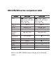
SBC-596/599 series comparison table Mo d el CPU System Chipset SB C-599 In t el : P54C, P55C (MMX) 75~200 MHz AMD: K5,K6 Cy r i x : M1, M2 SB C-596 In t el : P54C, P55C (MMX) 75~200 MHz AMD: K5,K6 Cy r i x : M1, M2 430TX 430TX Aw ard, PnP Aw ard, PnP 512 KB 512 KB 256 MB EDO 256 MB EDO C&T 65550 x LAN 10 BaseT, RTL8029 x SCSI 16-bit x High Drive 64 mA x USB 2 2 EIDE 4 4 BIOS L2 cache Max.
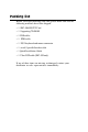
Packing list Before you begin installing your card, please make sure that the following materials have been shipped: • 1 SBC-596/599 CPU Card • 1 Supporting CD-ROM • 1 IDE cables • 1 FDD cable • 1 PS/2 keyboard and mouse connector • 1 serial/ 1 parallel bracket cable • 1 Quick Installation Guide • 1 Ultra SCSI cable (SBC-599 only) If any of these items are missing or damaged, contact your distributor or sales representative immediately.
Contents Chapter 1 General Information ................................... 1 Introduction ........................................................................... 2 Features .................................................................................. 2 Specifications ......................................................................... 3 Board layout and dimensions .............................................. 5 Chapter 2 Installation Guide ........................................ 7 Jumpers ..
Reset connector (CN3) ........................................................... 20 Keyboard lock connector (CN4) ............................................. 20 Fan power connector (CN5) .............................................. 21 SCSI connectors (CN6, CN7) ........................................... 21 IDE hard drive connectors (CN8, CN9) .......................... 21 Floppy connector (CN10) ..................................................... 22 Connecting the floppy drive ......................
Chapter 4 Award BIOS Setup ..................................... 39 System test and initialization ............................................ 40 System configuration verification ........................................... 40 AWARD BIOS setup .......................................................... 41 Entering setup ........................................................................ 41 Standard CMOS setup ........................................................... 42 BIOS features setup .........
Chapter 6 SCSI Setup and Configuration .................. 63 Installation and setup .............................................................. 64 SCSI configuration guidelines ................................................. 64 SCSI ID numbers ................................................................... 64 SCSI terminators .................................................................... 65 Installing SCSI devices ...........................................................
Appendix A Programming the Watchdog Timer .......... 91 Programming the watchdog timer ................................... 92 Appendix B Pin Assignments ........................................ 93 Speaker connector (CN1) ...................................................... 94 HDD LED connector (CN2) ................................................. 94 Reset connector (CN3) .......................................................... 94 Power LED/keyboard lock connector (CN4) ........................
CHAPTER 1 General Information This chapter gives background information on the SBC-596/599.
Introduction The SBC-596/599 is a full-size CPU card. This card uses a Pentium processor based CPU and accommodates up to 256 MB DRAM. It also provides a secondary level 512 KB cache, 2 USB(Universal Serial Bus) ports and 63-level watchdog timer with jumperless setup. The SBC-596/599 offers power management features to minimize power consumption. It complies with the “Green Function” standard and supports three power saving features: doze, sleep, and suspended mode.
Specifications Standard PC system • CPU: Intel Pentium up to 233 MHz, P54C, P55C(MMX) AMD K5, K6 Cyrix 6x86, Cyrix 6x86MX • BIOS: AWARD Flash BIOS, supports plug & play • Chipset: Intel 430TX • Secondary level cache: 512 KB on board • Green function: Supports power management option via BIOS, activated by keyboard or mouse activity. Supports doze, sleep, and suspended mode. APM 1.1 compliant • RAM: 8 MB to 256 MB, four 72-pin SIMM socket, accepts 4, 8, 16, 32 and 64 MB SIMMs.
- Panel resolution: Supports 640 x 480 @ 16M colors, up to 800 x 600 TFT panel - Display output: DB-15 VGA connector, 44 pin header general purpose flat panel display connector SCSI interface: (SBC-599 only) • PCI SCSI: Supports Ultra Wide SCSI 8-bit or 16-bit interface.
Board layout and dimensions 5.0 5.0 á 19.18 â ß á 3.81 81.33 â á 5.14 ß 48.01 â á 12.07 â á 63.35 â ß á1 5 . 0 â á 1.9 46.33 â á 42.5 â 5.0 ß 5.0 122.0 ßà 20.
6 SBC-596/599 User's Manual
CHAPTER 2 Installation Guide This Installation Guide tells how to set up the SBC-596/599 hardware, including instructions on setting jumpers and connecting peripherals, switches and indicators. Be sure to read all the safety precautions before you begin the installation procedure.
Jumpers The SBC-596/599 has a number of jumpers that allow you to configure your system to suit your applications. The table below lists the function of each of the board’s jumpers.
Connectors Onboard connectors link the SBC-596/599 to external devices such as hard disk drives, a keyboard, or floppy drives. The table below lists the function of each of the board’s connectors. Connectors Label CN1 Function Speaker CON. CN2 HDD LED CON. CN3 Reset switch CN4 Power LED/keyboard Lock CON. CN5 Fan Power CON. CN6 Wide SCSI CON. CN7 SCSI CON. CN8 Primary IDE CON. CN9 Secondary IDE CON. CN10 Floppy CON. CN11 Flat Panel CON. CN12 EXT Keyboard CON.
Locating jumpers J14 J13 J12 J11 J10 J9 J8 J7 J5 J15 J1 J2 J4 J3 10 SBC-596/599 User's Manual
Locating connectors CN16 CN13 CN20 CN18 UTP1 CN17 CN19 CN12 CN15 CN14 CN11 CN10 CN9 CN8 CN7 CN6 CN5 CN4 CN1 CN2 CN3 Chapter 2 Installation Guide 11
Setting jumpers You configure your card to match the needs of your application by setting jumpers. A jumper is the simplest kind of electric switch. It consists of two metal pins and a small metal clip (often protected by a plastic cover) that slides over the pins to connect them. To “close” a jumper you connect the pins with the clip. To “open” a jumper you remove the clip. Sometimes a jumper will have three pins, labeled 1, 2, and 3. In this case you would connect either pins 1 and 2 or 2 and 3.
CPU installation and upgrading You can upgrade to a higher power Pentium processor at any time. Simply remove the old CPU, install the new one, and set the jumpers for the new CPU type and speed. Warning! Caution! Always disconnect the power cord from your chassis when you are working on it. Do not make connections while the power is on as sensitive electronic components can be damaged by the sudden rush of power. Only experienced electronics personnel should open the PC chassis.
3. Press the lever down. The plate will slide forward. You will feel some resistance as the pressure starts to secure the CPU in the socket. This is normal and won‘t damage the CPU. When the CPU is installed, the lever should snap into place at the side of the socket. NOTE: To remove a CPU, pull the lever out to the side a little and raise it as far as it will go. Lift out the CPU chip. When you install a new CPU, be sure to adjust the board settings, such as CPU type and CPU clock.
Frequency Ratio (J5) This jumper sets the frequency ratio between the internal frequency of the CPU and the BUS Clock. If you use an AMD K6 CPU, please refer to J5 frequency ratio for K6 only. J5 Frequency Ratio** 2 2 5 6 2.5* 1 1.5*** 45 63 3 F.R. 2 1 3 45 6 3 45 63 2 4 1 2 1 4 J5 3 4 3 4 3 3 4 * Default setting ** Jumper settings for pins 1 and 2 do not affect this setting *** For Intel 233 MHz MMX CPUs, F.R. is 3.5 for this setting J5 Frequency Ratio for K6 only F.R.
MTXC CLK Setting/P55C Enabled (J7) This jumper setting provides Intel MTXC chipset 66/60 MHz frequency. You can Enable/Disable P55C CPUs with pin 1 and pin 2 close/open. J7 MTXC CLK Setting 66 Hz* 60 Hz 3 4 3 4 J7 J7 P55C Enabled/Disabled Enabled* Disabled J7 1 2 1 2 * default setting Clock Setting (J8) J8 must be set together with J5 jumper to match the CPU internal frequency. The clock frequency times the Frequency Ratio equals the CPU’s internal frequency. J8 Clock Setting CPU PCI 55 27.
Battery Select and Clear CMOS (J9) This jumper sets the CMOS data retention power supply by internal battery, external battery, or clear CMOS. J9 Battery Select J9 Internal Battery* 1 2 3 4 External Battery 1 2 3 4 Clear CMOS 1 2 3 4 * default setting SCSI Select (J10) (SBC-599 only) This jumper sets the data transfered by SCSI to 16-bit (Wide SCSI enabled) or 8-bit (Wide SCSI disabled).
LCD/EL Select (J13) This jumper sets the display type for the CPU card. J13 LCD/EL Select EL LCD* J13 1 2 3 1 2 3 * default setting Dual Power Select (J15) This jumper sets single power/dual power CPU type. Current Intel CPUs marked “Pentium” have only a single power plane and those marked “Pentium with MMX” have dual power planes.
Installing DRAM (SIMMs) The SBC-599 CPU card provides four 72-pin SIMM (Single Inline Memory Module) sockets and supports either Fast Page Mode (FPM) or Extended Data Output (EDO) DRAM with a speed of 70 ns or faster. You can install up to 256 MB of RAM. Installing SIMMs NOTE 1: Pentium or compatible processors adopt 64 bit data bus. Since 72-pin SIMM can only provide 32 bit data bus width, two SIMM modules are required as one memory bank, and both SIMMs must be the same size and type. 1.
Front panel connectors (CN1,CN2,CN3,CN4) You may want to install external switches to monitor and control the SBC-596/599. These features are optional —install them only if you need them. The front panel connectors include a speaker connector (CN1), a HDD LED connector (CN2), an input switch (CN3) for resetting the card, and a keyboard lock connector (CN4). Speaker connector (CN1) The SBC-596/599 can drive an 8 W speaker at 0.5 watts. Ensure that alternatives to this specification do not overload the card.
Fan power supply connector (CN5) CN5 provides power supply to optional CPU cooling fan. Only present when +12 V power is supplied to the board. SCSI connectors (CN6, CN7) (SBC-599 only) The SBC-599 has a 50-pin, dual-in-line connector for Ultra SCSI devices and a 68-pin, dual-in-line connector for Ultra Wide SCSI devices. Connection of SCSI devices requires special attention, especially when determining the last drive on the SCSI chain.
1. Connect one end of the cable to CN8/CN9. Make sure that the red (or blue) wire corresponds to pin 1 on the connector. 2. Plug the other end of the cable to the Enhanced IDE hard drive, with pin 1 on the cable corresponding to pin 1 on the hard drive. (See your hard drive’s documentation for the location of the connector.) Connect a second drive as described above. Unlike floppy drives, IDE hard drives can connect to either end of the cable.
Connecting the floppy drive 1. Plug the 34-pin flat-cable connector into CN10. Make sure that the red wire corresponds to pin one on the connector. 2. Attach the appropriate connector on the other end of the cable to the floppy drive(s). You can use only one connector in the set. The set on the end (after the twist in the cable) connects to the A: drive. The set in the middle connects to the B: drive. 3.
VGA interface connections (SBC-599 only) The SBC-599 PCI SVGA interface can drive conventional CRT displays and is capable of driving a wide range of flat panel displays, including electroluminescent (EL), gas plasma, passive LCD and active LCD displays. The board has two connectors to support these displays, one for standard CRT VGA monitors and one for flat panel displays. CRT connector (CN16) CN16 is a standard 15-pin D-SUB connector commonly used for VGA.
LCD power select 5V *3.3 V J12 * default setting Configuration of the VGA interface is done completely via the software utility. You don’t have to set any jumpers. Refer to Chapter 3 for software setup details. Refer to Chapter 3 for details on connecting the four standard LCD’s: Sharp LM64183P, LM64P89, Toshiba LTM10C042, Sharp 64C142, and Planar EL Display. Keyboard connectors (CN12, CN19) The SBC-596/599 board provides two keyboard connectors.
COM-port connectors (CN13, CN17) The SBC-596/599 has two serial ports, COM1 and COM2, to provide connections for serial devices (a mouse, etc.) or a communication network. You can find the pin assignments for the COM port connectors in Appendix B. The IRQ and the address range for COM1, 2, are fixed. However, if you wish to disable the port or change these parameters later you can do this in the system BIOS setup. The table below shows the settings for the SBC-599 Series serial ports.
USB connectors (CN18, CN20) The SBC-596/599 provides two USB (Universal Serial Bus) interfaces which gives complete plug and play, hot attach/detach for up to 127 external devices. The USB interfaces comply with USB specification rev. 1.0 and are fuse protected. The USB interfaces are accessed through two 5-pin flat-cable connectors, CN18 and CN20. You will need an adapter cable if you use a standard USB connector. The adapter cable has a 5-pin connector on one end and an USB connector on the other.
Watchdog timer configurationon An on-board watchdog timer reduces the chance of disruptions which EMP (electro-magnetic pulse) interference can cause. This is an invaluable protective device for standalone or unmanned applications. Setup involves one jumper and running the control software (refer to Appendix A). Watchdog select (J14) When the watchdog timer activates (CPU processing has come to a halt), it can reset the system or generate an interrupt on IRQ11.
CHAPTER Software Configuration 3 This chapter details the software configuration information. It shows you how to configure the card to match your application requirements. AWARD System BIOS is covered in Chapter 4.
Introduction The SBC-596/599 system BIOS and custom drivers are located in a 128 Kbyte, 32-pin (JEDEC spec.) Flash ROM device. A single Flash chip holds the system BIOS, VGA BIOS, and network Boot ROM image. The display can be configured via software. This method minimizes the number of chips and eases configuration. You can change the display BIOS simply by reprogramming the Flash chip.
AWDFLASH.EXE This program allows you to write the VGA display driver files to the BIOS Flash ROM. The VGA files all come ready formatted for the SBC-599 with .BIN extensions. They are custom written and can be made available upon request. 599_CRT.BIN System BIOS which supports CRT only 599_TFT.BIN System BIOS which supports 640X480 color TFT (Toshiba LTM10C042) 599_STN.BIN System BIOS which supports 640X480 color STN DD 8/16-bit displays (Sharp LM64C142) 599_MON.
VGA display software configuration (SBC-599 only) The SBC-599 on-board VGA interface supports a wide range of popular LCD, EL, gas plasma flat panel displays and traditional analog CRT monitors. With on-board 1M display memory, the interface can drive CRT displays with resolutions up to 1024 x 768 in 256 colors. It is also capable of extending up to 2 MB of display memory to provide resolutions of 1024 x 768 in 64K colors.
Connections for four standard LCDs (SBC-599 only) Connections to Sharp LM64183P, LM64P89 (640 x 480 DSTN MONO LCD) LM64183/64P89 SBC-599 CN11 Pin CN1-1 Pin name S Pin 36 Pin name FLM CN1-2 CP1 38 LP CN1-3 CP2 35 SHFCLK CN1-4 DISP 5 +5 V CN1-5 VDD 6 +5 V CN1-6 VSS 3 GND CN1-7 VEE - external power* CN1-8 DU0 12 P3 CN1-9 DU1 11 P2 CN1-10 DU2 10 P1 CN1-11 DU3 9 P0 CN1-12 DL0 16 P7 CN1-13 DL1 15 P6 CN1-14 DL2 14 P5 CN1-15 DL3 13 P4 *LM64183P -17V LM64P
Connections to PLANAR EL (640 x 480 AD4 EL) PLANAR 640 x 480 AD4 Pin 1 34 Pin name GND SBC-599H Pin 3 CN11 Pin name GND 2 DO 21 P12 3 GND 3 GND 4 D1 22 P13 5 GND 3 GND 6 D2 23 P14 7 NC — — 8 D3 24 P15 9 NC — — 10 D4 17 P8 11 NC — — 12 D5 18 P9 13 NC — — 14 D6 19 P10 15 GND 4 GND 16 D7 20 P11 17 GND 4 GND 18 VCLK 42 ASHFCLK 19 GND 4 GND 20 /BLANK — — 21 GND 8 GND 22 HS 37 M 23 NC — — 24 VS 36 FLM 25 NC — — 26
Connections to Toshiba LTM10C042 (640 x 480 TFT Color LCD) LTM10C042 PCA-6159H CN11 Pin Pin name 1 GND Pin 3 Pin name 2 CLK 35 SHFCLK 3 GND 4 GND 4 R0 27 P18 5 R1 28 P19 6 R2 29 P20 7 GND 8 GND 8 R3 30 P21 9 R4 31 P22 10 R5 32 P23 11 GND 33 GND 12 G0 19 P10 13 G1 20 P11 14 G2 21 P12 15 GND 33 GND 16 G3 22 P13 17 G4 23 P14 18 G5 24 P15 19 GND 34 GND 20 ENAB 37 M 21 GND 34 GND 22 B0 11 P2 23 B1 12 P3 24 B2 13 P4
Connections to Sharp LM64C142 (640 x 480 DSTN Color LCD) LM64C 142 SBC-599H CN11 Pin Pin name Pin Pin name CN1-1 YD 36 FLM CN1-2 LP 38 LP CN1-3 XCX 35 SHFCLK CN1-4 DISP 5 +5 V CN1-5 VDD 6 +5 V CN1-6 VSS 3 GND CN1-7 VEE - +27 V* CN1-8 DU0 20 P11 CN1-9 DU1 19 P10 CN1-10 DU2 18 P9 CN1-11 DU3 17 P8 CN1-12 DU4 12 P3 CN1-13 DU5 11 P2 CN1-14 DU6 10 P1 CN1-15 DU7 9 P0 CN2-1 VSS 4 GND CN2-2 DL0 24 P15 CN2-3 DL1 23 P14 CN2-4 DL2 22 P13
Ethernet software configuration (SBC-599 only) The SBC-599 on-board Ethernet interface supports all major network operating systems. To configure the medium type, to view the current configuration, or to run diagnostics, do the following: 1. Power the SBC-599 on. Ensure that the RSET8029.EXE file is located in the working drive. 2. At the prompt type RSET8029.EXE and press . The Ethernet configuration program will then be displayed. 3.
38 SBC-596/599 User's Manual
CHAPTER 4 Award BIOS Setup This chapter describes how to set BIOS configuration data.
System test and initialization These routines test and initialize board hardware. If the routines encounter an error during the tests, you will either hear a few short beeps or see an error message on the screen. There are two kinds of errors: fatal and non-fatal. The system can usually continue the boot up sequence with non-fatal errors.
AWARD BIOS setup Award’s BIOS ROM has a built-in Setup program that allows users to modify the basic system configuration. This type of information is stored in battery-backed CMOS RAM so that it retains the Setup information when the power is turned off. Entering setup Power on the computer and press immediately.
STANDARD CMOS SETUP When you choose the “STANDARD CMOS SETUP” option from the “INITIAL SETUP SCREEN” menu, the screen shown below is displayed. This standard Setup Menu allows users to configure system components such as date, time, hard disk drive, floppy drive and display. Once a field is highlighted, on-line help information is displayed in the left bottom of the Menu screen. *CMOS setup screen *Your BIOS configuration screen will look similar to this screen capture.
BIOS FEATURES SETUP The “BIOS FEATURES SETUP” option consists of configuration entries that allow you to improve your system performance, or let you set up some system features according to your preference. By choosing the “BIOS FEATURES SETUP” option from the INITIAL SETUP SCREEN menu, the screen below is displayed. This sample screen contains the manufacturer’s default values for the SBC-596/599. *BIOS features setup *Your BIOS configuration screen will look similar to this screen capture.
CHIPSET FEATURES SETUP This “CHIPSET FEATURES SETUP” option controls the configuration of the board’s chipset. By choosing the “CHIPSET FEATURES SETUP” option from the INITIAL SETUP SCREEN menu, the screen below is displayed. This sample screen contains the manufacturer’s default values for the SBC-596/599. *CHIPSET features setup *Your BIOS configuration screen will look similar to this screen capture.
POWER MANAGEMENT SETUP The “POWER MANAGEMENT SETUP” option allows you to reduce power consumption. This feature turns off the video display and shuts down the hard disk after a period of inactivity. By choosing the “POWER MANAGEMENT SETUP” option from the INITIAL SETUP SCREEN menu, the screen below is displayed. This sample screen contains the manufacturer’s default values for the SBC-596/599. *Power management setup *Your BIOS configuration screen will look similar to this screen capture.
PnP/PCI CONFIGURATION The “PnP/PCI CONFIGURATION” option configures the PCI bus slots. By choosing the “PnP/PCI CONFIGURATION” option from the Initial Setup Screen menu, the screen below is displayed. This sample screen contains the manufacturer’s default values for the SBC-596/599. *PnP/PCI Configuration *Your BIOS configuration screen will look similar to this screen capture.
INTEGRATED PERIPHERALS By choosing the “INTEGRATED PERIPHERALS” option from the INITIAL SETUP SCREEN menu, the screen below is displayed. This sample screen contains the manufacturer’s default values for the SBC-596/599. *Integrated Peripherals *Your BIOS configuration screen will look similar to this screen capture.
Load BIOS defaults “LOAD BIOS DEFAULTS” loads the default system values directly from ROM. If the stored record created by the Setup program becomes corrupted (and therefore unusable), these defaults will load automatically when you turn the SBC-596/599 on. *Load BIOS defaults screen *Your BIOS configuration screen will look similar to this screen capture.
USER PASSWORD To change the password, choose the USER PASSWORD option form the Setup main menu and press . 1. If the CMOS is bad or this option has never been used, a default password is stored in the ROM. The screen will display the following messages: Enter Password: Press . 2. If the CMOS is good or this option has been used to change the default password, the user is asked for the password stored in the CMOS.
AUTO DETECT HARD DISK The IDE HDD AUTO DETECTION utility can automatically detect the IDE hard disk installed in your system. You can use it to self-detect and/or correct the hard disk type configuration. *IDE HDD auto detection screen *Your BIOS configuration screen will look similar to this screen capture.
CHAPTER 5 PCI SVGA Setup (SBC-599 only) The SBC-599 features an on-board PCI flat panel/VGA interface. This chapter provides instructions for installing and operating the software drivers on the included Supporting CD-ROM.
Before you begin To facilitate the installation of the enhanced display device drivers and utility software, you should read the instructions in this chapter carefully before you attempt installation. The enhanced display drivers for the SBC-599 board are located on the software installation diskette. You must install the drivers and utility software by using the supplied SETUP program for DOS drivers NOTE: THE FILES ON THE SOFTWARE INSTALLATION DISKETTE ARE COMPRESSED.
Installation The drivers include Windows 3.1, Windows 95, Windows NT drivers, and OS/2 drivers. Simultaneous display mode The 65550 VGA BIOS supports monochrome LCD, EL, color TFT and STN LCD flat panel displays. It also supports interlaced and non-interlaced analog monitors (VGA color and VGA monochrome) in high-resolution modes while maintaining complete IBM VGA compatibility. Digital monitors (i.e. MDA, CGA, and EGA) are NOT supported.
Sleep mode The display driver contains two files that support sleep mode. Simply type the filename at the DOS prompt: ON.COM switches to normal display mode. OFF.COM switches to sleep mode. Driver installation Necessary prerequisites The instructions in this manual assume that you understand elementary concepts of MS-DOS and the IBM Personal Computer.
Before you begin The display driver contains drivers for several versions of certain applications. You must install the correct version in order for the driver to work properly so make sure you know which version of the application you have. Windows setup These drivers are designed to work with Microsoft Windows 3.1. You may install these drivers through Windows or in DOS. Step 1: Install Windows as you normally would for a VGA display. Run Windows to make sure that it is working correctly.
Changing Color Schemes After you change display drivers, you may notice that the color scheme used by Windows looks strange. This is because different drivers have different default colors. To change the color scheme, select the Control Panel from the Main window. Select the Color icon. You will be shown the current color scheme. Choose a new color scheme and click the OK button.
Windows 95 Drivers Setup Procedure 1. Boot system with VGA or SuperVGA driver. 2. Select properties from a menu after right button press. 3. Select display. 4. Select Change Display. 5. Select Change Monitor. 6. Select Change Adapter. 7. Select Have Disk.
Windows NT Drivers Setup Procedure Step 1 1. Install Windows NT as you normally would for a VGA display. 2. First click the Start button, choose Settings and click on Control Panel. 3. Choose the Display icon and click on the icon. 4. In the Display Properties window, click on the Settings tab. 5. Click on Change Display Type. In the Change Display Type window, click on the Change button under Adapter Type. This will bring up the Select Device window. Step 2 1.
OS/2 Drivers Setup Procedure Preliminary Steps The following steps must be performed before you install the 65550/554 display driver: 1. OS/2 DOS Support must be installed. 2. If you previously installed SVGA support, you must reset the system to VGA mode. VGA is the default video mode enabled when OS/2 is installed. To restore VGA mode, use Selective Install and select VGA for Primary Display.
A log of the information output during the install can be found in :\OS2\INSTALL\DISPLAY.LOG 4. After restarting the system, perform the following steps: 1). Open the OS/2 System folder. 2). Open the System Setup folder. 3). Open the Display Driver Install Object This step will execute the Display Driver Installation (DSPINSTL) utility program to finish installation of the new drivers. 4). When the Display Driver Install window appears, select Primary Display and then select OK. 5).
Selecting Monitor Type Monitor type is initially set to DEFAULT. This DEFAULT setting may not allow you to select all resolution/refresh combinations that are available for your monitor. The following steps can be done to select monitor type. This section applies only after installation, or when a different monitor is used. 1. Open the OS/2 System folder. 2. Open the System Setup folder. 3. Open the System object. 4. When the System - Settings notebook appears, select the Screen tab.
Installation Notes 1. During the installation of this driver, DISPLAY.LOG and DSPINSTL.LOG files are created in \OS2\INSTALL directory. These files identify the OS/2 system files that were updated, and indicate whether the installation was successful. The DISPLAY.LOG file also contains a string that identifies the version of driver that was installed. This information may be important when reporting an installation problem. 2. During installation, DSPINSTL will invoke the SVGA Configuration program SVGA.
CHAPTER 6 SCSI Setup and Configurations (SBC-599 only) The SBC-599 is equipped with two SCSI interfaces. This chapter provides basic SCSI concepts and instructions for installing the software drivers with the included SCSI driver diskettes. At the end of this chapter provides the SCSI device troubleshooting tips.
Installation and Setup The SBC-599 is equipped with an Adaptec AIC-7880 Ultra Wide PCI-to-Ultra SCSI host adapter which provides a powerful multitasking interface between your computer’s PCI bus and SCSI devices (disk drives, CD-ROM drives, scanners, tape backups, removable media drives, etc.). Up to a total of 15 SCSI devices can be connected to the internal or external SCSI connector on AIC-7880.
The AIC-7880 supports the SCSI Configured AutoMatically (SCAM) protocol, which assigns SCSI IDs dynamically and resolves SCSI ID conflicts automatically at bootup. If your system includes SCSI disk drives or other devices that support SCAM, you do not need to manually assign SCSI IDs to these devices. Most SCSI devices currently in use, however, do not support SCAM. The SCSI IDs on these devices must be set manually. To change the SCSI IDs on these devices, refer to the device’s documentation.
We recommend that you leave SCSI set to its default setting of Automatic. The following table lists the termination configurations. The following figures show termination examples for the AIC7880.
AIC-7880 Ultra Wide SCSI Termination Low High ON ON Chapter 6 SCSI Setup and Configurations 67
AIC-7880 Ultra Wide SCSI Termination Low OFF High ON SCSI Termination Examples Installing SCSI Devices You can connect up to 15 devices (seven standard internal and eight Wide (16-bit) internal SCSI devices, or 15 Wide internal SCSI devices) to the Ultra Wide SCSI. Connecting Internal SCSI Devices If you are connecting internal SCSI devices, make sure you have an internal SCSI cable with enough connectors to accommodate all of your devices. 1.
2. Install the SCSI device in your computer. Refer to your computer and device documentation for instructions. 3. Plug the connector at one end of the internal SCSI cable into the host adapter’s internal SCSI connector. Make sure the colored stripe on one side of the cable is aligned with pin-1 of the host adapter’s connector. Pin-1 of the connector is usually designated by a small triangle “D”, or a “1” on the connector. 4.
- When using 50-pin connector only, choose “Low ON/High ON” (Default) - When using 68-pin connector only, choose “Low ON/High ON” (Default) - When using both 50-pin & 68-pin, choose “Low OFF/High ON” Select the default of “Low ON/High ON?” and press Enter, then use the up and down arrows to make your new selection and press Enter. Press ESC to go back to the Options menu. Press ESC again and select Yes to exit the program.
Basic Host Adaptec Settings Host Adapter SCSI ID SCSI Parity Checking Host Adapter SCSI Termination Default 7 Enabled Low ON/High ON Boot Device Settings Default Boot Target ID Boot LUN Number1 0 0 SCSI Device Settings Default Initiate Sync Negotiation Maximum Sync Transfer Rate Enable Disconnection Initiate Wide Negotiation Send Start Unit Command Yes (Enabled) Yes (Enabled) 20 MBytes/sec Yes (Enabled) No (Disabled) Advanced Host Adapter Settings Default Plug and Play SCAM Support Disabled H
n n host adapter the highest priority on the SCSI bus. We recommend that you leave the host adapter set to SCSI ID7. SCSI Parity Checking - This option determines whether the host adapter verifies the accuracy of data transfer on the SCSI bus. The default setting is Enabled. You should disable SCSI Parity Checking if any SCSI device connected to the SBC-599 does not support SCSI parity; otherwise, leave it enabled. Most SCSI devices do support SCSI parity.
nInitiate Sync Negotiation - This option determines whether the host adapter initiates synchronous data transfer negotiation (Sync Negotiation) between the device and host adapter. The default setting is Yes. Synchronous negotiation is a SCSI feature that allows the host adapter and its attached SCSI devices to transfer data in synchronous mode. Synchronous data transfer is faster than asynchronous data transfer. The host adapter always responds to Sync Negotiation if the SCSI device initiates it.
When set to Yes, the host adapter attempts 16-bit transfer. When set to No, 8-bit data transfer is used unless the SCSI device itself requests Wide negotiation. The effective transfer rate is doubled when 16-bit data transfer is sued because the data path for Wide SCSI is twice the size of normal 8-bit SCSI. For example, a transfer rate of 10 Mbytes/sec becomes 20Mbytes/sec, and a transfer rate of 20 Mbytes/sec (Ultra SCSI) becomes 40 Mbytes/sec.
Setting this option to yes reduces the load on your computer’s power supply by allowing the host adapter to start SCSI devices one-at-a-time when you boot your computer. When set to No, the devices are allowed to start at the same time. Most devices require you to set a jumper before they can respond to this command. Note: If the Send Start Unit Command is set to yes for many devices, the boot time will vary depending on how long it takes each drive to start.
n Support Removable Disks Under BIOS as Fixed Disks — This option controls which removable-media drives are supported by the host adapter BIOS. This default setting is Boot Only. The following choices are available: Boot Only – Only the removable-media drive designated as the boot device is treated as a hard disk drive. All Disks – All removable-media drives supported by the BIOS are treated as hard disk drives. Disabled – No removable-media drives are treated as hard disk drives.
Extended BIOS Translation is used only with MS-DOS 5.0 or above. You do not need to enable this option if you are using another operating system such as NetWare, OS/s, Windows NT, or UNIX. When you partition a disk larger than 1 GByte, use the MS-DOS disk utility as you normally would. Because the cylinder size increases to 8 Mbytes under extended translation, the partition size you choose must be a multiple of 8Mbytes.
In some cases, selecting an option displays another menu. You can return to the previous menu at any time by pressing Esc. To restore the original SCSISelect default values, press F6. To toggle the display between color and monochrome modes, press F5 (this feature may not work on some kinds of monitors). Using the SCSI Disk Utilities To access the SCSI disk utilities, select the SCSI Disk Utilities option from the menu that appears after starting SCSISelect.
Installing Device Drivers Some operating systems embed (included) the AIC-7880 Ultra Wide SCSI device driver as part of their installation software. These drivers work fine with your AIC-7880 Ultra Wide SCSI; however, the most recent version of the driver should be installed in order for your AIC-7880 Ultra Wide SCSI to perform at its optimum level. n n Adaptec EZ-SCSI – allows you to install software drivers for DOS/Windows 3.x and several additional utilities.
ADAPTEC EZ-SCSI UTILITY Adaptec EZSCSI gives you what you need to use your SCSI devices most effectively with Windows 95 and Windows NT. You can also use Adaptec EZSCSI on computers running DOS, Windows 3.1x, or Windows for Workgroups 3.1x. Quick Start Instructions First, install SCSI devices (see the hardware documentation for details). Then follow the instructions for your operating system software in one of the following sections.
Troubleshooting Tips SCSI Device Troubleshooting Review this checklist if your newly installed SCSI disk drives, CDROM drives, and other devices do not seem to work properly: Be sure that termination is correctly set for all devices on the SCSI bus, as described in your host adapter documentation. Be sure there are no hardware conflicts such as devices in your computer trying to use the same interrupts (IRQs) or DMA channels.
What if there is no SCSI controller icon under Device Manager, or the model name of the SCSI chipset does not appear under Device Manager: If the SCSI controllers icon or your host adapter’s model name do not appear, open Control Panel and double-click the Add New Hardware icon. Let Windows search for the host adapter by selecting Yes on the second screen of the Add New Hardware Wizard. If Windows does not detect the host adapter, run the Add New Hardware Wizard again.
5. Turn the computer ON. If the new host adapter supports Plug and Play, Windows will install and configure it automatically. Otherwise, run Add New Hardware to make sure the new driver is loaded. If I am running under Windows 95, do I need lines for the Adaptec real mode ASPI drivers and mscdex in my config.sys and autoexec.bat files? Usually, you do not need to use these real mode ASPI drivers, because the new Windows miniport drivers support most SCSI host adapters and SCSI devices.
3. When you are finished running Adaptec EZSCSI for DOS, find the file named cdtsd.vxd in the windows\system\iosubsys directory and rename it cdtsd.sav. My CD-ROM drive shows up as more than one icon under My Computer. The mapping between mscdex, which runs in real mode, and the Windows95 CDROM driver does not match. You can correct this in one of two ways: - 84 Comment out the line that loads mscdex.exe in the autoexec.bat file. Change the /L switch on the line that loads mscdex.exe in the autoexec.
Information for DOS/Windows 3.1x Users The following information may be useful if you install Adaptec EZSCSI on a computer running DOS, Windows 3.1x, or Windows for Workgroups 3.1x. Note: The Windows 95/Windows NT Troubleshooting section describes a few situations when you may need to use the DOS/Windows 3.1x drivers and ASPI managers under Windows 95 or Windows NT. DOS and Windows 3.
Adaptec EZSCSI includes several ASPI managers for DOS/ Windows 3.1x. When you install Adaptec EZSCSI on these operating systems, it detects what kind of host adapter is installed in your computer and automatically configures your system with the correct ASPI manager. To learn more about these ASPI managers, including their command line option information, see the Adaptec EZSCSI Online Reference, a Windows Help application.
4. When the next screen appears, select either Format or Verify (to verify that the disk is free of surface defects), then press Enter. WARNING: Back up important data before you format the disk device! A low-level format erases all data from the disk. 5. If you select Format, confirm that you want to format the disk, then wait while the disk device is formatted. This may take a long time if the disk is large. If you select Verify, you can press Esc at any time to stop the verification process.
Run afdisk from the DOS prompt only, not from the Windows MSDOS prompt. Before you run it, be sure the disk devices you want to format and partition are connected to the host adapter and that they are powered. Then follow these steps: 1. 2. - - 88 Change to the directory where afdisk.exe is located (usually c:\scsi), type afdisk at the DOS prompt, and press Enter. Information about your SCSI disk devices appears on the screen. (The number that appears after Target is the device’s SCSI ID).
5. 6. 7. When the number of cylinders is what you want, press Esc. When the confirmation prompt appears, select Yes and press Enter to create the partition. To create more partitions on the same disk device, repeat steps 3,4, and 5. As you create partitions on the disk., they are added to the window at the upper right of the screen. Press Esc to return to the “Select SCSI Device to Partition” window.
90 SBC-596/599 User's Manual
A Programming the Watchdog Timer The SBC-596/599 is equipped with a watchdog timer that resets the CPU or generates an interrupt if processing comes to a standstill for whatever reason. This feature ensures system reliability in industrial standalone, or unmanned, environments.
Programming the Watchdog Timer In order to program the watchdog timer, you must write a program which writes I/O port address 443 (hex). The output data is a value of time interval. The value range is from 01(hex) to 3F(hex), and the related time interval is 1 sec. to 63 sec. Data 01 02 03 04 3F Time 1 2 3 4 Interval sec. sec. sec. sec. . . . 63 sec. After data entry, your program must refresh the watchdog timer by rewriting the I/O port 443 (hex) while simultaneously setting it.
B Pin Assignments This appendix contains information of a detailed or specialized nature.
Speaker connector (CN1) 1 2 3 4 SBC-596/599 Speaker connector (CN1) Pin 1 2 3 4 Signal VCC NC BZ SP HDD LED connector (CN2) 1 2 SBC-596/599 HDD LED connector (CN2) Pin 1 2 Signal GND + Reset connector (CN3) 1 2 SBC-596/599 Reset connector (CN3) Pin 1 2 94 Signal GND + SBC-596/599 User's Manual
Power LED/keyboard lock connector (CN4) 1 2 3 4 5 SBC-596/599 Keyboard lock connector (CN4) Pin 1 2 3 4 5 Signal PWLED NC GND KLOCK GND Fan power connector (CN5) 3 2 1 SBC-596/599 Fan power connector (CN5) Pin 1 2 3 Signal N/C GND +12 V Chapter B Pin Assignments 95
Wide SCSI connector (CN6) 34 33 68 67 .... 2 1 ....
SBC-599 Wide SCSI connector (CN6) Pin 47 49 51 53 55 57 59 61 63 65 67 Function SCD7 GND TRMPWR NC SATINSBSYSRSTSSELSREQSCD8 SCD10 Pin 48 50 52 54 56 58 60 62 64 66 68 Function SCDPL GND TRMPWR GND GND SACKSMSGSCDSIOSCD9 SCD11 Chapter B Pin Assignments 97
SCSI connector (CN7) 49 47 3 1 50 48 4 2 SBC-599 SCSI connector (CN7) Pin 1 3 5 7 9 11 13 15 17 19 21 23 25 27 29 31 33 35 37 39 41 43 45 47 49 98 Function GND GND GND GND GND GND GND GND GND GND GND GND GND GND GND GND GND GND GND GND GND GND GND GND GND SBC-596/599 User's Manual Pin 2 4 6 8 10 12 14 16 18 20 22 24 26 28 30 32 34 36 38 40 42 44 46 48 50 Function SCD0 SCD1 SCD2 SCD3 SCD4 SCD5 SCD6 SCD7 SCDPL GND GND GND TRMPWR GND GND SATINGND SBSYSACKSRSTSMSGSSELSCDSREQSIO-
IDE hard drive connectors (CN8, CN9) 33 31 3 1 34 32 4 2 SBC-596/599 IDE hard drive connector (CN8, CN9) Pin 1 3 5 7 9 11 13 15 17 19 21 23 25 27 29 31 33 35 37 39 Signal IDE RESET* DATA 7 DATA 6 DATA 5 DATA 4 DATA 3 DATA 2 DATA 1 DATA 0 SIGNAL GND HDD 1 IO WRITE IO READ HD READY HDACK 0* IRQ15/IRQ14** ADDR 1 ADDR 0 Pin 2 4 6 8 10 12 14 16 18 20 22 24 26 28 30 32 34 36 HARD DISK SELECT 0* 38 IDE ACTIVE* 40 Signal GND DATA 8 DATA 9 DATA 10 DATA 11 DATA 12 DATA 13 DATA 14 DATA 15 N/C GND GND GND N/C
Floppy connector (CN10) 33 31 3 1 34 32 4 2 SBC-596/599 Floppy connector (CN10) Pin 1 3 5 7 9 11 13 15 17 19 21 23 25 27 29 31 33 Signal Pin GND GND GND GND GND GND GND GND GND GND GND GND GND GND GND GND GND * Low active 100 SBC-596/599 User's Manual 2 4 6 8 10 12 14 16 18 20 22 24 26 28 30 32 34 Signal DENSITY SELECT* N/C N/C INDEX* MOTOR 0* DRIVE SELECT 1* DRIVE SELECT 0* MOTOR 1* DIRECTION* STEP* WRITE DATA* WRITE GATE* TRACK 0* WRITE PROTECT* READ DATA* HEAD SELECT* DISK CHANGE*
Flat panel connector (CN11) 43 41 3 1 44 42 4 2 SBC-599 Flat panel connector (CN11) Pin Function Pin Function 1 +12 V 2 +12 V 3 GND 4 GND 5 5V/3.3V 6 5V/3.3V 7 ENAVEE* 8 GND 9 P0 10 P1 11 P2 12 P3 13 P4 14 P5 15 P6 16 P7 17 P8 18 P9 19 P10 20 P11 21 P12 22 P13 23 P14 24 P15 25 P16 26 P17 27 P18 28 P19 29 P20 30 P21 31 P22 32 P23 33 GND 34 GND 35 SHFCLK/ASHFCLK 36 FLM 37 M 38 LP 39 GND 40 ENABKL* 41 KB_DT 42 KB_CK 43 N/C** 44 5V/3.
External keyboard connector (CN12) 5 4 3 2 1 SBC-596/599 External keyboard connector (CN12) Pin 1 2 3 4 5 102 Signal KB_CK KB_DT NC GND VCC SBC-596/599 User's Manual
COM port connectors (CN13: COM2, CN17: COM1) 6 5 10 1 6 9 5 1 SBC-596/599 COM port connectors (CN13, CN17) Pin 1 2 3 4 5 6 7 8 9 10 Signal DCD RX TX DTR GND DSR RTS CTS RI NC Chapter B Pin Assignments 103
Printer port connector (CN14) 13 12 2 1 26 25 1 5 14 SBC-596/599 printer port connector (CN14) Pin Signal 1 STROBE* 2 D0 3 D1 4 D2 5 D3 6 D4 7 D5 8 D6 9 D7 10 ACK* 11 BUSY 12 PE 13 SLCT * Low active 104 SBC-596/599 User's Manual Pin 14 15 16 17 18 19 20 21 22 23 24 25 26 Signal AUTOFD* ERR INIT* SLCTINI* GND GND GND GND GND GND GND GND N/C
IR connector (CN15) 5 4 3 2 1 SBC-596/599 IR connector (CN15) Pin 1 2 3 4 5 Signal VCC NC IR IN GND IR OUT CRT connector (CN16) 1 15 SBC-599 CRT display connector (CN16) Pin 1 2 3 4 5 6 7 8 Signal RED GREEN BLUE N/C GND GND GND GND Pin 9 10 11 12 13 14 15 Signal N/C GND N/C N/C H-SYNC V-SYNC N/C Chapter B Pin Assignments 105
USB connectors (CN18, CN20) 5 4 3 2 1 SBC-596/599 USB connectors (CN18, CN20) Pin 1 2 3 4 5 Signal +5 V UVUV+ GND N/C Keyboard and PS/2 mouse connector (CN19) SBC-596/599 Keyboard and mouse connector (CN19) Pin 1 2 3 4 5 6 106 Signal KB DT MS_DT GND VCC KB_CK MS_CK SBC-596/599 User's Manual
Ethernet 10BASE-T connector (UPT1) 9 7 5 3 1 10 8 6 4 2 SBC-599 Ethernet 10BASE-T connector (UPT1) Pin 1 2 3 4 5 6 7 8 9 10 Signal XMT+ XMTRCV+ N/C N/C RCVN/C N/C N/C N/C Chapter B Pin Assignments 107
108 SBC-596/599 User's Manual
C IRQ Default Settings Chapter C IRQ Default Settings 108
IRQ Default Settings IRQ15 IRQ14 IRQ12 IRQ11 IRQ10 IRQ9 IRQ7 IRQ6 IRQ5 IRQ4 IRQ3 IDE 2 IDE 1 (PS/2 mouse) USB/(SCSI) (LAN) LPT1 Floppy disk LPT 2 COM1 COM2 * IRQ 0, 1, 2, 8, 13 have been reserved for the system.