Theater Installation Guide 7!2 /& 7/2 -!. ,$3 ,!. $ / & ).3 "%' "!4 $ !2 4 9 '%3 $%! ,/. $ $3 2, 7/ $ /& $%! 2 7! /& $ . ,! ,/ .' "! %34 4- 9 !. !2 "% $ ') .3 7!2 /& 7/2,$ ,!.$ /& $%!$ ,/.'%34 9!2$ "!4-!. 0' 2 0' 0' "%7)4#(%$ &!.4!34)# 3)34%2(//$ -!$!'!3#!2 0' 0' 0' 0' © Copyright 2005-2006 Adaptive Micro Systems LLC. All rights reserved.
Theater Installation Guide (pn 97127016B) Revision history Part number Date 9712-7016 November 14, 2005 9712-7016B August 24, 2006 Notes First release. Reorganized manual to flow in a similar sequence as an installation occurs and to add networking and addressing information.
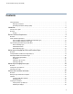
Theater Installation Guide (pn 97127016B) Contents Safety information . . . . . . . . . . . . . . . . . . . . . . . . . . . . . . . . . . . . . . . . . . . . . . . . . . . . . . . . . . . . . . . . . . . . . . . . . . . . . 5 Warnings and cautions. . . . . . . . . . . . . . . . . . . . . . . . . . . . . . . . . . . . . . . . . . . . . . . . . . . . . . . . . . . . . . . . . . . . . . 5 Controlling electrostatic discharge (ESD). . . . . . . . . . . . . . . . . . . . . . . . . . . . . . . . . . . . . . . . .
Theater Installation Guide (pn 97127016B) Appendix . . . . . . . . . . . . . . . . . . . . . . . . . . . . . . . . . . . . . . . . . . . . . . . . . . . . . . . . . . . . . . . . . . . . . . . 45 Sign identification . . . . . . . . . . . . . . . . . . . . . . . . . . . . . . . . . . . . . . . . . . . . . . . . . . . . . . . . . . . . . . . . . . . . . . . . . . . . .46 Converter Box . . . . . . . . . . . . . . . . . . . . . . . . . . . . . . . . . . . . . . . . . . . . . . . . . . . . . . . . . . . . . . .
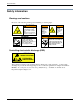
Safety information Safety information Warnings and cautions Be aware of the following warnings when installing or servicing signs. WARNING Hazardous voltage. Contact with high voltage may cause death or serious injury. Always disconnect power to unit prior to servicing. SM1000A 7!2.).' !6%24)33%-%.4 #/52!.4 $% &5)4% %,%6% 2ACCORDEMENT A LA TERRE INDISPENSABLE AVANT LE RACCORDEMENT AU RESEAU ()'( ,%!+!'% #522%.4 %ARTH CONNECTION ESSENTIAL BEFORE CONNECTING SUPPLY 3- ! 7!2.).' 7!2.).
Theater Installation Guide (pn 97127016B) Introduction 6
Introduction — How to use this guide How to use this guide This guide is intended to assist you with the configuration of ALPHA™ displays in your theater. Before you hang the first display and power it on, you need to ensure the data communication lines and electrical outlets are correctly wired and in the right locations. Once this has been accomplished, we recommend that you address the displays prior to mounting them. Finally, we address some basic setup steps for the Simply Theatre Signs software.
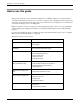
Introduction — Overview Overview This guide provides requirements and steps for installing Box Office, House, and Directional signs in a theater. Additionally, information regarding networking, addressing and installing Simply Theater Software is also provided. Figure 1: Sample signage arrangement in a theater. House signs 7!2 /& 7/2 -!. ,$3 ,!. $ / & $%! $ $3 2, 7/ $ /& %! 2 &$ ! 7 / .$ ,! Box Office sign Directional signs 7!2 /& 7/2,$ ,!.$ /& $%!$ ,/.'%34 9!2$ "!4-!.
Theater Installation Guide (pn 97127016B) Electrical and Data Requirements 9
Electrical and Data Requirements — Overview Overview 7!2 /& 7/2, !. ,!.$ /& %34 $%!$ .3 "%') "!4- $3 9!2$ ,/.' $3 2, 7/ $ /& $%! 2 7! /& $ . ,! ,/ .' "! %34 4- 9 !. !2 "% $ ') .3 7!2 /& 7/2,$ ,!.$ /& $%!$ ,/.'%34 9!2$ "!4-!. 0' 2 0' 0' "%7)4#(%$ &!.4!34)# 3)34%2(//$ -!$!'!3#!2 0' 0' 0' 0' Prior to hanging signs, power and data should be run to the sign locations.
Electrical and Data Requirements — Power and data requirements Power and data requirements Power and data hookups for Box Office and directional signs Important! All cables should be kept as short as possible to ensure effective communication. Figure 2: Power and communication hookup for Box Office and directional signs Power outlet should be right behind this plug. Do NOT put power outlet directly under this plug.
Electrical and Data Requirements — Power and data requirements Power and data hookups for house signs Important! All cables should be kept as short as possible to ensure effective communication.
Electrical and Data Requirements — Sign networking and addressing considerations Sign networking and addressing considerations About networking signs Signs must be networked together in a bus topology. The bus topology uses a single cable from one end of the network to the other end. Signs, computers, or other devices can be added throughout the network at different locations.
Electrical and Data Requirements — Sign networking and addressing considerations Other network topologies, such as the one in the following illustration, are not recommended. Figure 5: Unacceptable network topology: Star topology (multiple branches) !LPHA SIGN !LPHA SIGN !LPHA SIGN !LPHA SIGN !LPHA SIGN !LPHA SIGN !LPHA SIGN !LPHA SIGN RS485 Converter Box The signs communicate on an RS485 network which is the best choice for transferring messages over long distances.
Electrical and Data Requirements — Sign networking and addressing considerations Figure 7: Method 2 — Converter Box located in middle of sign network 23 DATA CABLE SEE ./4% BELOW #ONVERTER "OX PN 7!2 /& 4(% 7/2,$3 7!2 /& 4(% 7/2,$3 23 CABLE FOOT OR FOOT #OMMUNICATION 7ALL 0LATE #ONNECTIONS 7IRE CRIMP FOOT COMPUTER CABLE PN ./4% 0LENUM 23 DATA CABLE s !DAPTIVE "ELDIN .
Electrical and Data Requirements — Sign networking and addressing considerations Example A theater with multiple Box Offices wants to repeat the performance list three times. It takes two signs to display the full performance listing. These two signs are referred to as a “bank.” This same exact information can be repeated on the other two sign banks. To do this, they set the address for the first sign in each bank to 1 and the address for the second sign in each bank to 2.
Theater Installation Guide (pn 97127016B) Addressing and Hanging Box Office and Directional Signs 17
Addressing and Hanging Box Office and Directional Signs — Overview Overview 7!2 Directional sign Address = 10 /& Directional sign Address = 11 7/2, !. ,!.$ /& %34 $%!$ 9!2$ ,/.' $3 2, 7/ $ /& $%! 2 7! /& $ . ,! Box Office sign Address = 1 .3 "%') "!4- $3 ,/ .' "! %34 4- 9 !. !2 "% $ ') .3 7!2 /& 7/2,$ ,!.$ /& $%!$ ,/.'%34 9!2$ "!4-!. 0' 2 0' 0' "%7)4#(%$ &!.
Addressing and Hanging Box Office and Directional Signs — Setting Box Office and Directional Sign Addresses Setting Box Office and Directional Sign Addresses Step 1: Open the sign 1. Remove power from the sign. WARNING Hazardous voltage. Contact with high voltage may cause death or serious injury. Always disconnect power to unit prior to servicing. SM1000A 2. Remove the sign’s cover by loosening the clips that hold the cover in place: 3. Unscrew the vertical rails that hold the LED boards.
Addressing and Hanging Box Office and Directional Signs — Setting Box Office and Directional Sign Addresses Step 2: Set the sign’s DIP switches 1. Locate the sign’s DIP switches:.
Addressing and Hanging Box Office and Directional Signs — Setting Box Office and Directional Sign Addresses 2. Set the sign’s DIP switches as shown below: ON Set these DIP switches . . . For this address . . .
Addressing and Hanging Box Office and Directional Signs — Mounting Box Office and directional signs Mounting Box Office and directional signs Wall mounting specifications B D A C BACK OF BOX OFFICE OR DIRECTIONAL SIGN Theater Installation Guide (97127016B) Mounting brackets — used to mount the sign. Bottom brackets are only used if sign is mounted on an angle (see Figure 11 on page 26).
Addressing and Hanging Box Office and Directional Signs — Mounting Box Office and directional signs Table 2: Wall mounting specifications Dimensions Model number (see “Sign identification” on page 46) A (Height) B (Width) C (Vertical center-to-center distance between shoulder bolts) D (Horizontal center-to-center distance between shoulder bolts) Weight (approx.) TCM032006P02zzz 17.65 in. 44.8 cm. 43.20 in. 109.7 cm. 15.03 in. 38.2 cm. 40.58 in. 103.1 cm. 60 lbs. 27 kg. TCM032008P02zzz 22.
Addressing and Hanging Box Office and Directional Signs — Mounting Box Office and directional signs Table 2: Wall mounting specifications (Continued) Dimensions Model number (see “Sign identification” on page 46) A (Height) B (Width) C (Vertical center-to-center distance between shoulder bolts) D (Horizontal center-to-center distance between shoulder bolts) Weight (approx.) TCM024004P03zzz 17.92 in. 45.5 cm. 48.77 in. 123.9 cm. 15.30 in. 38.86 cm. 46.15 in. 117.2 cm. 55 lbs. 25 kg.
Addressing and Hanging Box Office and Directional Signs — Mounting Box Office and directional signs Preparation 7!2.).' WARNING 0OSSIBLE CRUSH HAZARD -OUNT UNIT ON A WALL THAT CAN SUPPORT AT LEAST TIMES THE UNITgS WEIGHT /THERWISE UNIT MAY FALL CAUSING SERIOUS INJURY OR DEATH Hazardous voltage. Contact with high voltage may cause death or serious injury. Always disconnect power to unit prior to servicing.
Addressing and Hanging Box Office and Directional Signs — Mounting Box Office and directional signs Mounting a sign on a wall Figure 10: Flush mounting Box Office or directional signs Mounting bracket (see below) BACK OF BOX OFFICE OR DIRECTIONAL SIGN Power/Communications panel Sign bumper For sign mounting dimensions, see “Wall mounting specifications” on page 22. Retaining pin Mounting bracket The fasteners that hold this bracket to a wall must be able to support 4 times the weight of the sign.
Addressing and Hanging Box Office and Directional Signs — Mounting Box Office and directional signs Mounting a light box A light box is used to display a Mylar transparency image. The HEIGHT and WIDTH of this image depends on the size of the light box used. A light box is typically placed directly under a Box Office or Lobby Directional sign.
Addressing and Hanging Box Office and Directional Signs — Mounting Box Office and directional signs Figure 13: Mounting light boxes "ACK VIEW 3IDE VIEW v (%)'(4 (%)'(4 n v v v v v $¿ v $ 7)$4( 3IDE VIEW -OUNTING BRACKET v 7ALL v v v X v !LPHA6ISION &3 SIGN .
Theater Installation Guide (pn 97127016B) Addressing and hanging house signs 29
Addressing and hanging house signs — Overview Overview House sign Address = 9 7!2 House sign Address = 4 /& 7/2, !. ,!.$ /& %34 $%!$ .3 "%') "!4- $3 9!2$ ,/.' $3 2, 7/ $ /& $%! 2 7! /& $ . ,! ,/ .' "! %34 4- 9 !. !2 "% $ ') .3 House sign Address = 7 House sign Address = 2 7!2 /& 7/2,$ ,!.$ /& $%!$ ,/.'%34 9!2$ "!4-!. 0' 2 0' 0' "%7)4#(%$ &!.
Addressing and hanging house signs — Setting house sign addresses Setting house sign addresses These instructions apply to the ALPHA™ 220C series signs. Addresses for ALPHA™ 4000 and 7000 series signs are set via the hand held remote. Refer to “Related documentation” on page ii for applicable documentation. Step 1: Open the sign: 1. Remove power from the sign. WARNING Hazardous voltage. Contact with high voltage may cause death or serious injury. Always disconnect power to unit prior to servicing.
Addressing and hanging house signs — Setting house sign addresses Step 2: Set the sign’s DIP switches 1. Locate the sign’s DIP switches: 2. Set the sign’s DIP switches as shown below:. ON Set these DIP switches . . . For this address . . .
Addressing and hanging house signs — Mounting house signs Mounting house signs These instructions explain how to mount ALPHA 220C signs using the available trim kits. For information about mounting other types of signs, refer to the appropriate manual, see “Related documentation” on page ii. 7!2.).' WARNING 0OSSIBLE CRUSH HAZARD -OUNT UNIT ON A WALL THAT CAN SUPPORT AT LEAST TIMES THE UNITgS WEIGHT /THERWISE UNIT MAY FALL CAUSING SERIOUS INJURY OR DEATH Hazardous voltage.
Addressing and hanging house signs — Mounting house signs Figure 15: Wall mounting Power outlet 7!2 ,EAVE AT LEA FROM TH ST A INCH CLE E SIGN TO THE ARANCE CEILING /& 4 (% 7 /2,$ 3 Communication wall plate — see “Sign networking and addressing considerations” on page 13. Shown with the optional Alpha 220C Trim Kit - Wall Mount (pn 68014013). 4/0 6)%7 IN IN IN IN &2/.
Theater Installation Guide (pn 97127016B) Software and Installation Verification 35
Software and Installation Verification — Overview Overview In this section, you will be performing the final stage of the theater sign installation. This is where you will connect the computer to the signs and install and configure the software so you can begin sending messages. The Simply Theater Signs (STS) software is used to communicate to the signs. This software was designed to make it easier for you to complete the installation and configuration in as quick a time as possible.
Software and Installation Verification — Wiring the sign network to the computer Wiring the sign network to the computer The following figure depicts an example of wiring the sign network to the computer running Simply Theater Signs. For more information, refer to “Networking Alpha Signs” (part number 97000112).
Software and Installation Verification — Software Software Installing Simply Done Software To install Simply Done Software, insert the CD-ROM into the drive and follow the prompts. If the CDROM does not automatically start, do the following: 1. Double-click the My Computer icon on the desktop. 2. Navigate to the CD-ROM drive (double-click the drive letter with the CD-ROM in it). 3. Double-click setup.exe and follow the prompts.
Software and Installation Verification — Software 2. Click the Communication Ports tab and then click the Edit button and make the appropriate changes. Figure 18: Editing the communication ports. Set the communication port settings as they apply to your location. To set the number of houses: 1. Access the Dealer Maintenance Options screen in Simply Theatre Signs. Figure 19: Accessing the Dealer Maintenance Options screen. To access the Dealer Maintenance Options screen, click this icon.
Software and Installation Verification — Software 2. Click the Number of Houses tab and then click the Edit button. Update the number of houses and click the Commit Change button when done. Figure 20: Setting the number of houses.
Software and Installation Verification — Software To configure the point of sale: 1. Access the General Settings screen. Figure 21: Accessing the Configuration screen. A. Click Configuration. Figure 22: Accessing the General Settings screen. B. Click General Settings.
Software and Installation Verification — Software 2. Click the General Options tab, click Edit, and check the Use Point of Sale System box. Figure 23: Enabling the POS option. Check the Use Point of Sale System box. 3. Click the Point of Sale System tab and set the options as appropriate for the point of sale system used in your theater. Figure 24: Configuring the point of sale system information.
Software and Installation Verification — Verifying the installation Verifying the installation Verifying house sign addresses When the house signs first boot up, they will display their hex address. Verify this is correct based on the house number. Refer to “About addressing signs” on page 15 for more information. Rebooting the displays These instructions apply to Box Office, directional, and outdoor signs because these signs must be reset in order to configure the memory and establish communications.
Software and Installation Verification — Verifying the installation 2. Click the ellipse button. Figure 26: Box Office sign emulator. Click this button to reset the sign. 3. Wait approximately two (2) minutes for the sign to reset. 4. Move to the next sign or emulator and reset the next sign. Figure 27: Moving to the next sign in the emulator. Use the slider to move to the next sign. You can navigate between signs using the slider in all of the emulators.
Theater Installation Guide (pn 97127016B) Appendix 45
Appendix — Sign identification Sign identification B -/$%, ./ 3%2)%3 6/,43 (Z !-03 4#- 0 2%$ " 6!# ^ (Z &4 & & / 2 ) . $ / / 2 5 3 % / . ,9 #%24)&)%$ 4/ #!. #3! 34$ # .O #/.&/2-3 4/ 86 !.3) 5, 34$ .O #/-0,)%3 4/ 34$ !3 .:3 4(% $)34).
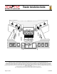
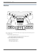
Appendix — Converter Box Converter Box Front view A Back view F E D C B Table 3: Converter Box components Item A Name Description RS-232 TXD indicator Flashing = data being sent from the computer to the sign(s). RS-232 RXD indicator Flashing = data being sent from the sign(s) to the computer. Power indicator Lit = power is supplied to Converter Box. B RS-485 jack Optional RS485 connection. C Termination switch To turn Converter Box termination on, set switch to TERMINATED.
Appendix — RS485 data cable information RS485 data cable information Two types of RS485 data cable are available from Adaptive: •RS485 plenum cable (7124-0203) — indoor/outdoor cable. If this cable is used outdoors, it should be encased in a UV-protectant casing. •RS485 non-plenum cable (7122-0203) — indoor cable. Table 4: RS485 plenum cable (7124-0203) Description 1/Pr.
Appendix — RS485 data cable information Table 5: RS485 non-plenum cable (7122-0203) Description 1/Pr. 22 AWG FPE shielded cable, 100% aluminum Mylar and 95% tinned copper braid, 300V Type NEC/PLTC LO-CAP (Belden 3105A equivalent) Conductor AWG size and stranding: 22 AWG 7/0.0096 Material: Tinned copper Material: FPE - Foam Polyethylene Wall thickness: 0.020 inch Insulation Color code Assembly Black/Red Lay length: 2.5 inch L-H-L Binder: None Shield #1: Aluminum polyester foil shield.
Appendix — Adaptive Micro Systems Contact Information Adaptive Micro Systems Contact Information Customer Service Telephone:1-800-719-2838 or 1-414-357-2020, extension 274. Technical Support Technical support is offered twenty-four hours a day seven days a week. Telephone: 1-414-357-2020 extension 519. USA HEADQUARTERS 7840 North 86th Street Milwaukee, WI USA 53224 Tel: 414-357-2020 Fax: 414-357-2029 Email: sales@adaptivedisplays.