Dot Matrix Printer SP300 Series Programmer’s Manual
TABLE OF CONTENTS 1. CONTROL PANEL .............................................................................. 1 1-1. Basic Operation ............................................................................ 1 1-2. Switch Operation (Combined Switch Operation) ........................ 2 2. SERIAL INTERFACE .......................................................................... 7 2-1. Interface Specifications ................................................................ 7 2-2. Interface Circuit ..
7. CONTROL CODES ............................................................................ 29 7-1. Control Codes Used for Character Setting ................................. 32 7-2. Control Codes Used for Line Spacing ....................................... 36 7-3. Control Codes Used for Page Layout ......................................... 37 7-4. Control Codes Used for Graphics Printing ................................ 41 7-5. Control Codes Used for Download Characters ..........................
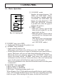
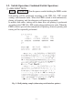
1. CONTROL PANEL 1-1. Basic Operation POWER ALARM 3 4 5 ON LINE 1 FEED 2 Fig. 1-1 Control panel 1 “ON LINE” switch Switches the printer between “ON LINE” and “OFF LINE”. Whenever the printer switches between “ON LINE” and “OFF LINE”, the buzzer gives one short beep (“ON LINE” and “OFF LINE”, switching is possible only when the paper is loaded in the printer.) 2 “FEED” switch • When this switch is pressed and then released within 0.5 sec.,the paper feeds one line.
1-2. Switch Operation (Combined Switch Operation) 1 FEED + POWER ON (Turn the power on while holding the FEED switch depressed.) Self-printing will be performed according to the VER. NO., DIP switch settings and character order. When the FEED switch is held continuously during self printing, only the characters will print out repeatedly. In models with cutter, cutting will be done after self-printing is performed according to the VER. NO., DIP switch setting and character order.
2 ON LINE + POWER ON (Turn the power on while holding the ON LINE switch depressed.) Each of the signals sent from the computer to the printer will be printed out in hexadecimal code. This function allows you to check if a control code sent to the printer by the program being used is correct or not. The buzzer will sound once to indicate the printer is in hexadecimal dump mode. After the program has been run, the last line buffer should be flushed by pressing the ON LINE switch.
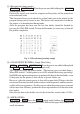
5 (Sprocket-type Only) ON LINE + FEED (Press the FEED button while holding the ON LINE button depressed when the printer is ON LINE) The buzzer gives three short beeps and the printer sets the page top. 6 (Twin Head Only) FEED + ON LINE + POWER ON This mode enables adjustment of the forward and backward printed line alignment by 1/2-dot increments. The adjustment procedure is explained on the following pages.
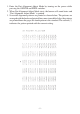
1. Enter the Dot Alignment Adjust Mode by turning on the power while pressing the ONLINE and FEED switches. 2. When Dot Alignment Adjust Mode starts, the buzzer will sound twice and “Dot Alignment Adjust Mode” is printed. 3. Seven dot alignment patterns are printed as shown below. The patterns are arranged with the backward printed lines more toward the left as the patterns are printed down the page; the fourth pattern is the standard. The asterisk (*) indicates the pattern printed with the current setting.
4. To choose a pattern with a closer alignment of the forward and backward printed lines, count from the top down to the desired pattern and press the FEED switch the counted number of times. (The buzzer sounds each time the FEED switch is pressed, up to a maximum of seven times. However, if the FEED switch is pressed more than seven times, a warning sounds.) 5. Press the ONLINE switch after the setting is made.
2. SERIAL INTERFACE 2-1. Interface Specifications 1 Data transmission method: 2 Baud rate: Asynchronous serial interface Selectable from 150, 300, 600, 1200, 2400, 4800, 9600, 19200 (Twin Head only) bps (Refer to Installation Manual.) Start bit: 1 bit Data bit: 7 or 8 bits (selectable. Refer to Installation Manual.) Parity bit: Odd, even or none (selectable. Refer to Installation Manual.
2-2. Interface Circuit 2-2-1. RS-232C Serial Interface Input (RXD, CTS) Printer Host computer 75189 or equivalent Output (DTR, FAULT, TXD, RCH, RTS) Printer Host computer 75188 or equivalent Fig . 2-1 RS-232C interface circuit 2-2-2. Current Loop (option) Input (TTY-RXD, TTY-RXDR) Host computer +V R Printer Output (TTY-TXD, TTY-TXDR) Host computer +V R Printer Note: Adjust “R” so that the loop current is set within 10 to 20 mA. Fig.
2-2-3. RS-422A Serial Interface (option) Input (RD, RS) Printer Host computer A B Output (SD, CS) Printer Host computer A B Fig.
2-3. Connectors and Signals RS-232C Pin no. Signal name 1 2 3 4 F-GND TXD RXD RTS I/O direction — OUT IN OUT 5 CTS IN 6 7 8 9-10 N/C S-GND N/C N/C 11 RCH OUT 12 13 14 N/C S-GND FAULT — OUT 15 16 17 to 19 Multi-printer TXD Multi-printer DTR N/C OUT OUT 20 DTR OUT 21-22 23 to 25 N/C N/C — Function Frame ground Transmitted data Received data Data transmission request signal. This is always “SPACE” when the printer is turned on.
20 mA current loop (option) Pin no. Signal name 9 TTY TXDR I/O direction — 10 17 TTY TXD TTY TXDR OUT — 18 TTY RXDR — 19 23 TTY RXD TTY RXDR IN — 24 25 TTY TXD TTY RXD OUT IN Function Indicates the ground side of the data signal of 20 mA loop current. Transmitted data of 20 mA current loop. Indicates the ground side of the data signal of 20 mA loop current. Indicates the ground side of the data signal of 20 mA loop current. Received data of 20 mA current loop.
2-4. Interface Connections The following is a basic example of interface connections. (For interface connections, refer to the specifications for the respective interface.) IBM PC type serial port is shown as example.
2-5. Installing the Optional Interface Board When using the optional 20 mA current loop interface or the RS-422A interface, the optional interface board must be mounted to the printer’s main logic board. The following is the method of mounting the interface board to the printer’s main logic board. 1 Remove the 6 screws on the bottom cover of the printer, then remove the bottom cover. 2 Connect the optional interface board connector to connector CN9 on the printer’s main logic board.
2-6. Data Structure 2-6-1. DTR mode This mode is accessed when the DIP switch 3-5 is ON. Signals are controlled using the DTR line as BUSY flag. Data RXD Data Buffer full Data Buffer empty DTR Printing Power ON When paper is out RXD OFF LINE ON LINE DTR Printing Paper out Press the ON LINE switch after loading paper. PAPER OUT signal Power ON If a printer errors do not occur after the power is turned on, the DTR signal line changes to “SPACE”.
Data buffer Full Near Empty Near Full Remainder 256 bytes Empty 256 bytes DTR “MARK” DTR “SPACE” [Paper out] When the “paper out’ detector senses the end of the paper, the printer stops printing after printing a maximum of two more lines or on feeding the paper. Immediately after a “paper out” condition is detected, the printer sets to OFF LINE and the DTR changes to “MARK”. (To reset printer after a “paper out’, load paper into the printer and press the ON LINE switch to set the printer to ON LINE.
[Framing error] A framing error occurs when SPACE is detected at the stop bit. When a framing error or a vertical parity error occurs for the data which is received, the printer prints out a “?” mark to indicate that the error occurred. [Compulsion switch] When pin 6 of the peripheral unit drive circuit connector is set “HIGH”, status bit 7 becomes “1”. 2-6-2. X-ON/X-OFF mode This mode accessed when the DIP switch 3-5 is OFF.
Data buffer Full Near Empty Near Full Remainder 256 bytes Empty 256 bytes X-OFF X-ON [Paper out] When the “paper out” detector senses the end of the paper, the printer stops printing after printing a maximum of two more lines or on feeding the paper. The printer will set the DTR to “MARK” and set the printer to OFF LINE five seconds after a “paper out” condition is detected.
[Status] b7 b6 b5 b4 b3 b2 b1 b0 0 Constantly set at “0” Vertical parity error 1: error Framing error 1: error Mechanical error 1: error Paper empty 1: empty Buffer empty 1: empty Buffer overflow 1: overflow Compulsion switch High level (Switch is set to ON) [Framing error] A framing error occurs when SPACE is detected at the stop bit. When a framing error or a vertical parity error occurs for the data which is received, the printer prints out a “?” mark to indicate that the error occurred.
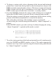
2-6-3. STX-ETX mode This mode is accessed from whichever DTR mode or X-ON/X-OFF mode. To set this mode, the data buffer must be empty. The host computer sends an ENQ code to the printer and acknowledges the printer status. Then, the host computer checks if the printer buffer is empty. After the host computer detects that the buffer is empty, a STX code and data are transmitted.
[Compulsion switch] When pin 6 of the peripheral unit drive circuit connector is set at “HIGH”, status bit 7 becomes “1”.
Starts the STX-ETX mode. Sends an Sends Receives status signal. Receives status byte. NO Receives a check byte. Is the data buffer empty? Is the status an error? YES Horizontal parity check Sends Is an odd parity check? NO YES NO Check byte = test byte? NO YES YES (FF) H is set for the text byte. The test byte is set at (0)H.
3. PARALLEL INTERFACE 3-1. Interface Specifications This printer has a parallel interface to communicate with the computer. The operating specifications of the parallel interface are as follows. (1) (2) (3) (4) Data transfer rate Synchronization Handshaking Logic level : : : : 1000 to 6000 characters per second Via externally supplied STROBE pulses ACK and BUSY signals Compatible with TTL level 3-2. Interface Timing ACK About 9ms Data STROBE T T T BUSY T:more than 0.5 microsec. Fig.
Signal Name Circuit Example 4.7KW INPUT DATA 1 – DATA 8 (To Printer) 74 HC Compatible 4.7KW 4.7KW STROBE (To Printer) 74 HC Compatible 100W OUTPUT 470pF 4.7KW 74 HC Compatible BUSY, ACK (From Printer) Fig.
3-3. Connectors and Signals Pin no 1 Signal name STROBE Direction IN 2-9 DATA 1-8 IN 10 ACK OUT 11 BUSY OUT 12 PAPER OUT OUT 13 14-15 16 17 18 19-30 31 SELECTED OUT N/C SIGNAL GND CHASSIS GND +5VDC GND RESET IN 32 ERROR 33 34 35-36 EXT GND COMPULSION OUT N/C (19) OUT Function Signals when data is ready to be read. Signal goes from HIGH to LOW (for at least 0.5 microsec.) when data is available. These signals provide the information of the first to eighth bits of parallel data.
4. EMERGENCY SUSPENSION If any of the following errors is detected while the printer is operating, the printer halts and ERROR signal turns to “LOW” level. 1 Mechanical errors • Motor lock • Defective of timing detector (signal not issued) • Abnormal home position check. • Defective cutter movement (paper jam, etc.
5. VALIDATION PRINTING (Models with validation function only) This printer can print one line of validation printing. 5-1. Operating Method B 1 Open the front cover, pull the adjust lever one notch from standard position A toward the operation panel side position B. When you cannot find standard position A, push the lever as far as possible toward the rear cover, and pull it 2 notches after having pressed it down. The lever is now in standard position A. A 2 Mount the front cover.
5-2. Printing Format Prints one line in 7 × 9 font normal printing. 32 columns (from the 5th to 36th columns) Even if the setting for the paper width is changed by the DIP switch, the 32column format will not change. 5-3. Data format 5-4. Other Min. 70 • The FEED and ON LINE switches will not operate normally during validation printing.
6. AUTO CUTTER (Auto-cutting models only) 6-1. Cutting Method Cuts recording paper into continuous forms connected at only one point remaining uncut between adjacent forms. Only one sheet of paper can be cut each time. 6-2. Cutting position The paper is cut approximately 21.7 mm above the printing head. Center of printer Cutting position Partial cutting with one uncut point left Approx. 21.7mm Printing head position Fig. 6-1 Cutting method Fig. 6-2 Cutting position 6-3.
7.
Control Codes Used for Page Layout Control codes “C” n “C” <0> n “B” n1 n2 “N” n “O” “1” n “Q” n “D” n1 n2 Hexadecimal codes 0C 1B 43 n 1B 43 00 n 1B 42 n1 n2 0B 1B 4E n 1B 4F 1B 6C n 1B 51 n 1B 44 n1 n2 09 Function Page feed (form feed) Set page length at n lines Set page length at n inches Set vertical tab positions Execute vertical tab Set bottom margin Cancel bottom margin Set left margin Set right margin Set horizontal tab position Execut
Control Codes Used for Peripheral Units Control codes n1 n2 Hexadecimal codes 1B 07 n1 n2 07 1C 1A 19 Function Adjust drive pulse width for peripheral unit 1 Deferred drive command for peripheral unit 1 Immediate drive command for peripheral unit 1 Immediate drive command for peripheral unit 2 Immediate drive command for peripheral unit 1 Page 49 49 49 50 50 Other Control Codes Control codes “U” “1” “U” <1> “U” “0” “U” <0>
7-1. Control Codes Used for Character Setting FUNCTION Select international character set CODE “R” n DEFINITION RANGE (1B)H (52)H n OUTLINE (00)H n (08)H Select the international character set corresponding to the value set for n. (03)H: England (06)H: Italy n =(00)H: U.S.A.
FUNCTION Select 7 × 9 (half dot) font CODE “M” (1B)H (4D)H OUTLINE Selects 7 × 9 (half dot) font. Refer to User’s manual for the maximum number of print columns. When the power of the printer is turned on, 7 × 9 (half dot) printing is automatically selected. This code valid only when received at the beginning of a line. FUNCTION Select 5 × 9 (2 pulses = 1 dot) font CODE “P” (1B)H (50)H OUTLINE Selects 5 × 9 (2 pulses = 1 dot) font.
FUNCTION Cancel expanded character mode CODE (14)H OUTLINE Cancels expanded character mode set by or “W” “1” or “W” <1> code. Data following this code is printed out in normal size characters. Same as “W” “0” or “W” <0>. FUNCTION Select expanded character mode CODE “W” “1” or “W” <1> (1B)H (57)H (31)H or (1B)H (57)H (01)H OUTLINE Data following this code is printed in double-width characters. Same as .
FUNCTION Select underline mode CODE “-” “1” or “-” <1> (1B)H (2D)H (31)H or (1B)H (2D)H (01)H OUTLINE Data following this code is printed out underlined. (However, the spaces generated by horizontal tab are not underlined.) FUNCTION Cancel underline mode CODE “-” “0” or “-” <0> (1B)H (2D)H (30)H or (1B)H (2D)H (00)H OUTLINE Cancels underlined mode.
FUNCTION Cancel highlighted print mode CODE “5” (1B)H (35)H OUTLINE Cancels highlighted print mode. FUNCTION Select inverted print mode CODE (0F)H OUTLINE Data following this code is printed out in inverted characters. This code is valid only when input at the beginning of a line, thus, normal and inverted characters cannot be mixed in on the same line. FUNCTION Cancel inverted print mode CODE (12)H OUTLINE Cancels the inverted character mode.
FUNCTION Set 1/8-inch line feed CODE “0” (1B)H (30)H OUTLINE Line feed is set at 1/8-inch after this code is received. FUNCTION Feed paper n lines CODE “a” n (1B)H (61)H n DEFINITION RANG 1 OUTLINE 7-3. n 127 After data in the line buffer is printed out, feeds the paper n lines. Control Codes Used for Page Layout FUNCTION Page feed (form feed) CODE (0C)H OUTLINE After data in the line buffer is printed out, feeds the paper to the top of the next page.
FUNCTION Set vertical tab positions CODE “B” n1 n2...nk <0> (1B)H (42)H n1 n2...nk (00)H DEFINITION RANGE 1 OUTLINE Cancels all current vertical tab positions and sets new vertical tab positions at lines n1, n2, etc., where n1, n2, etc. are numbers between 1 and 255. A maximum of 16 vertical tab positions can be set. Tab positions must be specified in ascending order; any violation of ascending order terminates the tab position list. Standard termination is by the <0> control code.
FUNCTION Cancel bottom margin CODE “O” (1B)H (4F)H OUTLINE Cancels bottom margin. FUNCTION Set left margin CODE “1” n (1B)H (6C)H n DEFINITION RANGE 0 OUTLINE Sets the left margin at column n in the current character pitch. The left margin does not move if the character pitch is changed later. The left margin must be at least two columns to the left of the right margin and within the limits above.
FUNCTION Set horizontal tab position CODE “D” n1 n2...nk <0> (1B)H (44)H n1 n2...nk (00)H DEFINITION RANGE 1 1 OUTLINE Cancels all current horizontal tab positions and sets new tab positions at columns n1, n2, etc. in the current character pitch, where n1, n2, etc. are numbers between 1 and (Maximum print columns–1). The maximum number of horizontal tab positions allowed is 16.
7-4. Control Codes Used for Graphics Printing FUNCTION Set 7/72-inch line feed CODE “1” (1B)H (31)H OUTLINE Line feed is set at 7/72-inch after this code is received. FUNCTION Define n/72-inch line feed CODE “A” n (1B)H (41)H n DEFINITION RANGE 0 OUTLINE Line feed is defined at n/72-inch after this code is received. This code sets the feed at n/72-inch with the “2” code.
FUNCTION Set n/216-inch line feed simulation CODE “3” n (1B)H (33)H n DEFINITION RANGE 1 OUTLINE Line feed is set at n/216-inch after this code is received. According to the minimum paper feed pitch of the connected mechanism, the amount of line feed is set as follows: For 1/72”-pitch mechanisms: INT {(n/3)}/72-inch. For 1/144”-pitch mechanisms: INT {(2n/3)+0.5}/144-inch.
EXAMPLE Actually, let us consider printing as a means of bit image. We will create the design below using bit image. m1 m2 m3 m4 m5 m6 m7 m8 m9 m10 m11 m12 m13 m14 m15 m16 m17 m18 m19 m20 m21 m22 m23 m24 m25 m26 m27 m28 m29 m30 D8 D7 D6 D5 D4 D3 D2 D1 First, since the volume of data is 30, n1 = (1E) H. If the data m1 ~ m30 is converted to hexadecimal, it appears as shown below.
FUNCTION 8 dot double density bit image CODE “L” n1 n2 m1 m2... (1B)H (4C)H n1 n2 m1 m2... DEFINITION RANGE 1 OUTLINE Executes double density bit image printing (half-dot printing) determined by “n1” and “n2”. The total number of bit image data bytes in one line is equal to n1 + n2 × 256. Refer to K as to the relation between the dot position and the bit number. The printer ignores any data bytes over the specified amount allowed in one line.
FUNCTION Select vertical expaned character mode CODE “h” “1” or “h” <1> (1B)H (68)H (31)H or (1B)H (68)H (01)H OUTLINE Prints characters two times the normal vertical size after the code is received. However, the bit image mode “K” and “L” are excluded. NOTE (1) When combined with the code, this code enables printing of the characters in two times the normal vertical and horizontal size. (2) This code is not combined with the inverted print mode code.
7-5.
FUNCTION Enable download character set CODE “%” “1” or “%” <1> (1B)H (25)H (31)H or (1B)H (25)H (01)H OUTLINE Enables the download character set Download characters defined by the ESC & 0 code cannot be printed until enabled by this command. FUNCTION Disable download character set CODE “%” “0” or “%” <0> (1B)H (25)H (30)H or (1B)H (25)H (00)H OUTLINE Disables the selected download character set and selects the built-in character set.
Data Binary Hexadecimal Data Binary Hexadecimal Data Binary Hexadecimal m1 10100000 A0 m1 10011000 98 m1 00111000 3C m2 00000000 00 m2 01100100 64 m2 01000010 42 m3 10100000 A0 m3 10000010 82 m3 10100101 A5 m4 00011111 1F m4 00000001 01 m4 00000000 00 m5 10100000 A0 m5 10000010 82 m5 10100101 A5 m6 00000000 00 m6 01100100 64 m6 01000010 42 m7 10100000 A0 m7 10011000 98 m7 00111000 3C Example of transmitting data (1) Definition of download characters (1B)H (A0)H (A0)H (82)H (A5
7-6. Control Codes Used for Peripheral Units FUNCTION Adjust drive pulse width for peripheral unit 1 CODE n1 n2 (1B)H (07)H n1 n2 DEFINITION RANGE 1 OUTLINE Adjusts drive pulse width for peripheral devices requiring other than standard 200 ms pulse time and delay time Energizing time = 10 × n1 (ms) Delay time = 10 × n2 (ms) Executed by , codes. n1 127, 1 n2 127 (default setting n1 = n2 = 20) ON OFF 10 × n1 (ms) 10 × n2 (ms) Printing and paper feed are prohibited.
FUNCTION Immediate drive command for peripheral unit 2 CODE (1A)H OUTLINE Drives peripheral unit 2. Pulse width is fixed at 200ms with a fixed delay time of 200 ms. When the printer receives a code, the command is executed immediately. Same as NOTE Peripheral units 1 and 2 cannot be driven simultaneously. FUNCTION Immediate drive command for peripheral unit 2 CODE (19)H OUTLINE Dives peripheral unit 2. Pulse width is fixed at 200 ms with a fixed delay time of 200 ms.
FUNCTION Set deselect mode CODE (13)H OUTLINE (1) When using serial interface printer: This function differs depending on the setting of DIP switch 4. a) When the DC1, DC3 invalid mode is set (DIP switches 4-1 to 4-4 are all set to ON), the printer ignores this code. b) In the DC1, DC3 valid mode (with DIP switches 4-1 to 4-4 set to OFF), data following this code is ignored when the printer receives a code. The deselect mode is canceled by code.
c) If the printer receives a n code (n is the DIP switch controlled address) during the addressable mode (with DIP switches 4-1 to 4-4 set other than settings a) and b) above,), the deselect mode is canceled and data following this code is input to the buffer. Note that addressable mode is valid only when optional RS-422A interface is installed.
FUNCTION Enquiry CODE (05)H OUTLINE This code is valid when using serial interface printer. Online in STX-ETX mode: The printer sends the status data and the check byte to the host computer. Online in any other mode: The printer sends only the status data to the host computer. Offline in any mode: The printer only sends the status data to the host computer if there is a mechanical error in the status bit, or if the paper out or power down bit is set.
FUNCTION Trigger auto-cutter drive (Auto-cutting models only) CODE “d” “0” or “d” <0> (1B)H (64)H (30)H or (1B)H (64)H (00)H “d” “1” or “d” <1> (1B)H (64)H (31)H or (1B)H (64)H (01)H OUTLINE This code causes the printer to trigger auto-cutter. FUNCTION Select validation printing (Models with validation function only) CODE data (1D)H data (0A) OUTLINE Prints up to 32 columns of the 7 × 9 (half dot) font size characters on one line.
8. CHARACTER CODE TABLES 8.1 U.S.A.
– 56 –
8.
– 58 –
8.
– 60 –
8.
– 62 –
8.
MEMO
ELECTRONIC PRODUCTS DIVISION STAR MICRONICS CO., LTD. OVERSEAS SUBSIDIARY COMPANIES STAR MICRONICS AMERICA, INC. 536 Nanatsushinnya, Shimizu, Shizuoka, 424-0066 Japan Tel: 0543-47-0112, Fax: 0543-48-5013 1150 King Georges Post Road, Edison, NJ 08837-3729 U.S.A. Tel: 732-623-5555, Fax: 732-623-5590 Please access the following URL http://www.star-micronics.co.jp/service/frame_sp_spr_e.htm for the lastest revision of the manual. STAR MICRONICS U.K. LTD.