
User's Manual


Interwave Wave2000 BSS Specification Printed 11/21/02 12:29 PM
Interwave Wave2000 BSS Specification.docInterwave Proprietary Information 21 of 32
Each radio has 3 coax interfaces at the front panel. The upper and lower coax port are for dual receive
inputs, while the center is for transmit. Each radio module is designed to support a specific frequency band.
Current versions available support the 800 MHz (cellular) and 1900 MHz (PCS) bands. Each radio
interfaces to a channel card via the backplane.
The micro power supply card generates all voltages for the shelf, using the 20 to 35VDC input. The primary
voltage used by all cards is 6.5VDC. The power supply also generates 12VDC for the GPS module, and 3.3
VDC as bias for Ethernet transformers on backplane.
The backplane has 14 slots for the front mounted cards. Slots are keyed using card mounted grounding pins,
to prevent improper insertion of card types.
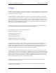
At rear of backplane are several connectors as follows:
Microcell Power: 10 pin, requires voltage between 20 to 35 VDC. Diode protected against accidental
reverse voltage.
Microcell enable: 2 pin, when shorted together will enable microcell power supply. Will be disabled when
open circuit. This is intended to connect to an external alarm control unit, which monitors ambient
conditions to ensure microcell is operated only within recommended temperature and voltage ranges.
Alarm Control Port: DB9 port for RS-232 connection to external alarm control unit.
2PPS: coax, used to output pulse per two seconds used for RF receiver measurement with
external test equipment.
GPS Port: DB9 port for RS-232 connection to GPS receiver.
GPS Power: 2 pin, provides 12VDC for GPS unit.
GPS 10M: coax, used to receive 10 MHz frequency reference from GPS unit.
GPS 1PPS: coax, used to receive 1 pulse pre second signal from GPS unit.