
User's Manual Part 4


4-18 LGCell Installation
The duplex ports have a variable gain. Please see the table for system
gain under “Maximum Input RF Power per Carrier vs. Number of
Carriers” on page 17 in
Section 2, LGCell Equipment
.
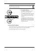
Downlink (Forward) and Uplink (Reverse) Connectors
Connect an N-type male RF coaxial cable to
the downlink N-type female connector
(labeled
FORWARD
) and an N-type male RF
coaxial cable to the uplink N-type female
connector (labeled
REVERSE
) on the Main Hub
back panel.
Connect the other ends of the coaxial cable to
the MBS. For diagrams of connecting LG
Cell
to specific MBS equipment, see
Section 5,
Connectivity
.
For simplex MBSs,
be sure
the MBS
downlink
coaxial cable connector
plugs into the downlink connector, and the
uplink
coaxial cable
connector plugs into the uplink connector on the Main Hub.
Alarm Report Monitor
A separately orderable option for use with LG
Cell
, the Alarm Report Monitor is an
alarm monitoring, reporting, and remote control system. Up to 255 remote-ARM
monitoring units can monitor up to 2,040 LG
Cell
systems. Each remote-ARM unit
communicates with the ARM software through a dial-up modem connection, using
an external or internal modem. A database of these devices is set up in a PC, with a
unique address for each device.
The ARM supports multiple users and tracks responsibility through log-in and log-
out procedures, using four security levels to protect critical system functions. It
features a graphic color status display, remote system reset control, alarm history
and control logs, security code management, and journal printer and paging options.
For ARM installation instructions, see
Appendix E – Alarm Report Monitor
(ARM2000)
.
a060
DUPLEX
FORWARD
REVERSE