Appendix A – Cables, Connectors, and Accessories This section provides information about cables, connectors, and accessories that an LGCell application might require. LGC Wireless can provide these components, or the customer can. If the customer provides them, they must be on-site when LGC Wireless personnel arrive.
A-2 Appendix A – Cables, Connectors, and Accessories
Cables and Connectors The following cables and connectors are required for connecting LGCell. They are not provided with the LGCell equipment and must be on site or installed at the site prior to the LGCell installation. LGC wireless can provide and install these cables and connectors. Determine which cables (and their length) and connectors you need, then order them through a cable vendor or installer.
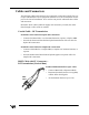
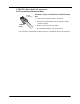
UTP/STP Cable with RJ-45 connectors – RF Transmission (Horizontal Run) Standard Category 5 Unshielded or Shielded Twisted Pair RJ-45 Connector • Connects the Expansion Hub to the RAUs. UTP/STP Cable a029 • Transmits (downlink) and receives (uplink) cellular and PCS signals. • Delivers electrical power to RAUs. • Accommodates distances up to 60 meters. LGC Wireless recommends plenum-rated CAT 5 UTP/STP cable and connectors.
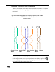
Unshielded Twisted Pair Cable Termination All UTP (Unshielded Twisted Pair) shall be terminated according to the TIA/EIA 568-A standard. The following diagram describes how the four pairs should be terminated. Top View of the Wiring Map for Category 5 (CAT 5) UTP Cable (TIA/EIA 568-A Standard) Straight Connect 1 2 3 4 5 6 7 8 Green/ Green Orange/ Blue Blue/ Orange Brown/ Brown White White White White The UTP/STP cable can be any length from 10 meters up to 60 meters.
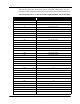
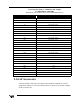
The next two tables show how system gain on the uplink and downlink vary as a function of cable length (horizontal run, measured with 1 km of Multi-Mode Fiber). LGCell System Gain vs.
LGCell System Gain vs.
A-8 Appendix A – Cables, Connectors, and Accessories
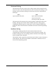
Appendix B – TIA/EIA 568-A Cabling Standard This appendix is a summary of the TIA/EIA 568-A Commercial Building Telecommunications Cabling Standard. The TIA/EIA 568-A commercial building cabling standard addresses the need for a common criterion covering cabling in commercial buildings. The standard was drafted to ensure support for a wide variety of applications, devices, and vendor products.
Horizontal Wiring The horizontal cable is the portion of the cabling system which extends from the work area outlet to the telecommunications closet. The horizontal cabling is a star topology, with a maximum cabling run of 90 meters (295 feet), independent of media type. Voice 4-pair 100 ohm UTP cable Data 4-pair 100 ohm UTP/STP 2-pair 150 ohm STA 62.5/125 µm fiber optic cable The horizontal cable amounts to the greatest quantity of individual cables in the building.
Multi-Mode Optical Fiber Cable 62.5/125 micron Optical Fiber Cable 62.5/125 µm Optical Fiber Cable 3000m (9843 ft.) HC MC 500m (1640 ft.) IC 2000m (6560 ft.) Maximum HC 2500m (8202 ft.) 500m (1640 ft.) Maximum 100Ohm UTP Cable for Voice HC 90m (295 ft) Maximum MC 500m (1640 ft.) Maximum IC 1500m (4920 ft.) Note 1 100Ohm UTP Cable for Data 800m (2624 ft) Maximum TC MC IC 300m (984 ft.
Equipment Room The equipment room is the area in a building where telecommunications equipment is located. Parts of or all of the telecommunications cabling system terminate here. Entrance Facilities The entrance facility is where outside telecommunications service enters the building, and interconnects with the building's internal telecommunications systems. In a campus or multi-building environment, the entrance facility may also contain the building's backbone interconnects.
Appendix C – Compliance Information All LGCell systems comply with Optical Fiber Safety Standard IEC/EM60825-2. The LGCell distributed antenna system is rated as a Class 1 laser hazard system. It has an absolute maximum output power of -11.5 dBm at 1300 nanometers (nm). There are no restriction on the location or use of an LGCell system. No special precautions are required if standard work practices are followed.
DAS8M-2-W: Telecom: FCC: NOO-DAS800-1 (FCC Part 22.901d) Non-Broadcast Transmitter Industry Canada: 3077281151A for the “Cellular 800” (RSS128, Issue 1) EMC: FCC: Class A, Part 15, Subpart B Industry Canada: Same as FCC Safety: UL 1950, 3rd Edition and the cUL mark for the Canadian equivalent. NEBS: This is a customer driven conformance certification and typically desired of equipment that is intended to be installed in a Central Office environment.
FCC Regulatory Notice: This device complies with Part 15 of the FCC Rules. Operation is subject to the following two conditions: • This device may not cause harmful interference. • This device must accept any interference received, including interference that may cause undesired operation. Industry Canada Regulatory Notice: This Class B (or Class A, if so indicated on the registration label) digital apparatus meets the requirements of the Canadian Interference-Causing Equipment Regulations.
C-4 Appendix C – Compliance Information
C-5
IEC/EN 60825-2 - Safe Use of Optical Fiber Communication Systems Part 2 of IEC 60825 provides requirements and specific guidance for the safe use of optical fiber communications where optical power may be accessible at some distance from the optical source. In this part of IEC 825, light emitting diodes (LED’s) are included whenever the word “laser” is used. Description of LGCell System The LGCell is a distributed antenna system. It consists of three main components.
3.14 location with restricted access: A location where access to the protective housing is restricted and not open to the public. Examples include industrial and commercial premises, PBX rooms, computer system rooms, and optical test sets. Distributed fiber networks may pass through unrestricted public areas, restricted areas within premises, as well as controlled areas or they may be deployed entirely within restricted business premises. 3.
LGCell fiber optic system is -11.5 dBm. Therefore there is no restriction as to location of use of the LGCell system and there is no labeling requirement. Suggested Work Practices The LGCell is covered under these parts of section D7 of 60825 The following working practices are suggested for working on the LGCell system: C-8 • Viewing Fiber: Do not stare with unprotected eyes at the connector ends of the fibers or the ports of the hub.
Appendix D – Services This appendix gives an overview of services that LGC Wireless provides. LGC Wireless offers a full range of professional services to ensure cost-effective and timely deployment of wireless networks. The seasoned staff of dedicated service professionals at LGC Wireless combine wireless system design and implementation expertise with a commitment to customer satisfaction unequalled in the industry.
Appendix E – Alarm Report Monitor (ARM2000) This appendix describes the Alarm Report Monitor (ARM2000) system, an option that you can order separately, for monitoring LGCell, PCS Extender, and Fiber Extender alarms. If your LGCell is connected to a microcellular base station, see the Integration Module Installation and Reference Manual for installation and operation of alarm devices and connectivity for that system. Contents Appendix E – Alarm Report Monitor (ARM2000) Description of the ARM2000 System .
E-2 Appendix E – Alarm Report Monitor (ARM2000)
Description of the ARM2000 System The Alarm Report Monitor (ARM2000) software is used to display, manage, and record the alarm monitoring activity of one or more remote-ARM (ARM2000-RU) alarm monitoring and remote control units. The software provides a graphical display of up to 255 of these units and enables the user to identify and acknowledge alarm events, reset alarms, maintain event history, and page field service personnel.
ARM2000 System Basics The ARM2000 system is an alarm monitoring, reporting, and remote control system. Up to 8,160 individual alarm points can be monitored, displayed and logged by the system. The system consists of up to 255 remote-ARM monitoring units that can monitor up to 2,040 LGC systems (LGCell, PCS Extender, Fiber Extender) and a Pentium PC running the ARM software. These remote-ARM units communicate with the ARM software through dial-up modem connections.
Modem Connections Communications to or from the remote ARM can be configured in either of two ways: • Internal modem (inside remote-ARM unit) The internal modem must be a North American qualified modem for use in telephone networks that use North American standard call progress tones. This modem is inside the remote-ARM unit and requires an analog phone line connection with an RJ-11 male connector. Connect the phone line to the port marked “Line” in COM1, at the back of the remote ARM.
J6 Alarms 11,12 – Main Hub 6 J7 Alarms 13,14 – Main Hub 7 J8 Alarms 15,16 – Main Hub 8 Input Alarm input to ARM unit Output Remote Reset from ARM unit Alarm Cable and Connectors Test Setup After the ARM unit is powered up, the unit should be reset and ready for communicating to the PCARM system for final programing. When the ARM is powered, wait 15 seconds and then press the TEST button on the left front of the unit.
PCARM Programming Information If multiple ARM200-RU units are installed that will be controlled by one PCARM system, then each ARM200-RU unit must be configured with a unique device ID (1-255) for programming by the PCARM system. Each ARM unit must have a different device ID if it will be controlled by one PCARM system. There is a label on each ARM unit that indicates what device ID it has be configured for.
Once connected to COM1, enter AT and press Enter. (You will see OK displayed at this point and will not see any characters.) Then enter the following AT commands. • “AT&F” • “AT&A0” • “AT&B1” • “AT&K0” • “AT&M0” • “AT&N3” • “AT&W” After you enter these commands, your PCARM modem is ready for communication with the internal modem of the remote ARM. Exit HyperTerminal. (You do not need to save this session).
11 Enter the dial-up number (the PCARM modem number) that the remote ARM will dial to establish communications with the PCARM. If you need to enter a digit to access an outside line (such as 9), separate this digit from the phone number with a comma for a pause. Enter 1 for long distance if required. 12 End the session by entering “ATH0”. 13 Exit HyperTerminal. You do not have to save the session.
To set up PCARM software 1 Double click the PCARM.exe shortcut icon that you created. The System View screen appears. 2 Click setup. 3 Click Configure ARM Manager (change the configurations to desired settings). Make sure “use modem” is YES. Once changes have been made, save the changes and exit. 4 Click Setup (again). 5 Click Device. 6 Click Remote Arm. 7 Enter the device address (0001, for example). 8 Enter the location (LGC Wireless, for example).
Modem Connections Communications to or from the remote-ARM unit can be configured in either of two ways: • The internal modem (inside the remote-ARM unit) uses North American call progress tones. • External Modem (via RS-232 COM1) used for International locations when North American call progress tones are not used. Internal Modem: (Required parts: cable with RJ-11 male connectors on both ends) The internal modem is situated inside the remote-ARM unit.
Security Setup To access the security utility, click Setup on the Device View or System View screen. Choose the desired security system by placing the cursor in the appropriate box and clicking. For a secure system you will need to enter a name, password (security code), and clearance level for each individual who will use the system. In a secure system at least one operator must have a Level 3 security clearance.
Security Setup Utility Overview The Security Setup Utility enables the user to setup the various security features of the ARM. It is made up of two different screens. One to select the system wide security options and the other to enter the system operators. Access to the Security Setup Utility You can access the Security Setup Utility from the System View or Device View screen or the Control Panel. From any of these, select Setup / Security.
Security Options Screen Security Options Fields To select a Security Setup field, use the SPACEBAR key or position the cursor over the field you want and click the left mouse button. You can set up the security of the system in one of three ways: • Open system In an open system, all functions are available at all times. No log-on or log-off procedure is required. This is the least secure system. • Tracked system In a tracked system, each user is assigned a security level and an access code.
Security Codes Screen The Security Codes screen enables the system supervisor (highest security, Level 3) to change or add operator names and security codes and assign individual security levels. Security Code Levels • Level 0 Allows a user to view status and history screens and to print reports. At this level, the user will not be able to acknowledge alarms. Any attempt to perform a function will result in a prompt for a higher security code or log on.
Alarm and Device Setup During the initial test after you complete the setup, PCARM displays the appropriate clear and alarm conditions. To acknowledge these conditions, click the ACK button on the Device View screen. During initial setup, all 16 devices are assumed to be enabled. Disabling Alarms and Devices To disable an alarm, place the mouse pointer over the alarm and right click. PCARM displays a dialog box that asks if you want to be reminded to enable after an elapsed time.
E-17
Resetting the Main Hub Remotely The remote-ARM unit is designed not only to monitor the alarm conditions, but also to reset the Main Hub from a remote site. When an alarm condition occurs, you can clear the alarm from the PCARM via the control menu and then reset the Main Hub. To reset an alarm condition remotely 1 2 From the Device View screen, click Control Menu to go to the Control Panel screen. Choose a hub to reset by clicking that hub.
4 Choose your time and press Enter If the alarm condition has cleared, the PC buzzer sounds and a status box appears on your screen. 5 Click Go To. PCARM displays the Device View screen, on which the cleared alarm(s) flash green. 6 To acknowledge the clear condition, click ACK. The flashing green indicator or indicators become solid green.
Pulse Duration Dialog Box Control Panel Status Box E-20 Appendix E – Alarm Report Monitor (ARM2000)
PCARM Operations To display, manage, and record alarm monitoring activity in PCARM, you can perform operations from the System View, Device View, and Alarm View screens. You can also enable and disable alarms and devices from the System View and Device View screens. System View Screen Overview of the System View Screen The System View screen displays the current status for all of devices in the entire system. On the screen, 255 windows display the status for each device in the system.
Window Status Indicators Window State Condition Green All circuits clear and acknowledged. Red Alarm condition on one or more channels. All alarms are acknowledged. Green Flashing Unacknowledged clear event on one or more channels. Red Flashing Unacknowledged alarm on one or more channels. Red/Green Flashing Both alarms and clears that are unacknowledged. Blue Flashing Unit is not responding to polls. Yellow The device is output only. Gray Unit is not programmed.
Status Bar The status bar is located on the bottom of the System View screen. It displays the current status of the system. It has three status windows. The function of each of these windows is described in the following sections: Communications Port Status This window is used to display the current status of the communications port. If the system is configured to be directly connected to a device it will display “Direct Connect”.
• Setup This selection displays a pull down menu with the following five choices: Config ARM: This selection accesses the ARM configuration utility. Device: This selection displays a sub-menu that allows access to the device setup utilities as described below. REMOTE-ARM: This selection accesses the remote-ARM setup utility. Security: This selection accesses the Security Setup utility. Log On: This selection displays the Log On Dialog Box. Log Off: This selection displays the Log Off Dialog Box.
Device View Screen Overview of the Device View Screen The Device View screen displays a Graphic Color Status Display of any individual front panel with animation of all alarm reporting functions. Each Device View has the location name of the device printed at the top of the screen (LGC Wireless in the example above). When no alarms are present all channel LED’s are green, there is a message ‘ALL CLEAR’, and the time. Each LED has an associated name (Short Name) printed above it.
When you are at the Device View screen, if an event occurs on another device, a New Event dialog box will pop up over the Device View screen. The New Event dialog box offers the following choices: • Go To Select to display the device that is alarming. • System View Select to display System View screen. • Continue Select to continue with the device that is presently displayed. Acknowledging Alarms Alarms and Clears are both acknowledged in the same manner.
Communications Test Function A communications test function has been provided to test communications between ARM and the remote-ARM unit and update the status. This should be done after a new device is installed. To test a device, position the cursor over the test button and click the left mouse button and ARM will call the remote-ARM unit. When the test is complete a dialog box stating the result of the test will be displayed. Status Bar There is a status bar located at the bottom of the screen.
Reports You can display the following reports in PCARM: • Alarm History Log • Alarm History by Device • Alarm Detail Alarm History Log The Chronological Alarm History screen displays the entire contents of the Alarm History Log in chronological order (newest to oldest). A scroll bar on the right hand side of the screen is provided to scroll through the alarm log. The scroll bar thumb shows the current position in the file.
• Time the event was acknowledged • Initials of who acknowledged the event Operator Log The Operator Log is a chronological history (newest to oldest) of the operators who have logged on to the system. This screen contains columns to display the operator name, time logged on, and the time logged off. You can access the Operator Log only from the System View screen. Select Operator Log from the main menu.
Alarm Logs To print an alarm log, select the log you want and then select Print from the log screen’s menu. Control Logs To print a control log, display the log and then select Print from the log screen’s menu. Current Alarms ARM provides the ability to print a list of all current alarms (acknowledged and unacknowledged) to a printer. To print all current alarms, select Print Current Alarms from the menu on the System View screen.