
User's Manual


ADCP-75-130 • Issue 3C • August 2006
Page 50
© 2006, ADC Telecommunications, Inc.
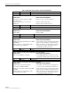
Table 12. DEU Fault Isolation and Troubleshooting Guidelines
Alarm Type LED LED COLOR
Minor UNIT Yellow
Problem : The DEU is overheating.
POSSIBLE CAUSE CORRECTIVE ACTION/COMMENTS
1. Air intake or exhaust openings to DEU
chassis blocked.
2. Ambient temperature > 50º C/122º F.
3. Faulty fan.
1. Remove cause of air-flow blockage.
2. Reduce ambient temperature.
3. Replace fan (see Subsection 6.5).
Alarm Type LED LED COLOR
Major UNIT Red
Problem : The DEU detects an internal circuitry fault.
POSSIBLE CAUSE CORRECTIVE ACTION/COMMENTS
1. Faulty DEU. 1. Replace DEU.
Alarm Type LED LED COLOR
Major HOST PORT Blinking Red
Problem: The DEU is not receiving an optical signal from the DHU.
POSSIBLE CAUSE CORRECTIVE ACTION/COMMENTS
1. Faulty forward path optical fiber between DEU
and DHU (2).
2. Faulty optical receive port at DEU or faulty
optical transmit port at DHU (2).
1. Clean optical connector and then test optical fiber.
Repair or replace if faulty (see Subsection 6.4.2).
2. Make sure transceiver is fully plugged it and then
test optical port. Replace optical transceiver if
port is faulty (see Subsection 6.4.1).
Alarm Type LED LED COLOR
Minor OK/NOK Yellow
Problem: The DEU is receiving a minor alarm signal from a connected DEU.
POSSIBLE CAUSE CORRECTIVE ACTION/COMMENTS
1. The connected DEU is overheating. 1. Check DEU UNIT indicator and then refer to the
appropriate troubleshooting section for procedures.
Alarm Type LED LED COLOR
Major OK/NOK Blinking Red
Problem: The DEU is not receiving an optical signal from the DRU.
POSSIBLE CAUSE CORRECTIVE ACTION/COMMENTS
1. Forward and reverse path optical fibers
reversed between DEU and DRU.
2. Faulty reverse path optical fiber between DEU
and DRU.
3. Faulty optical receive port at DEU or faulty
optical transmit port at DRU.
1. Check fiber connections for correct polarity and
reverse connectors at either unit if mismatched.
2. Clean optical connector and then test optical fiber.
Repair or replace if faulty (see Subsection 6.4.2).
3. Make sure transceiver is fully plugged in and then
test optical port. Replace optical transceiver if
port is faulty (see Subsection 6.4.1).
(Continued)