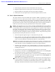
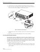
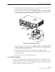
FCC ID: F8I-DISSMRAA, Partial User Manual, 3 of 4 ADCP-75-136 • Issue 1 • November 2002 5. Insert the optical transceiver into the socket until it locks into place. 6. Replace the optical transceiver dust cap if it was removed for installation. 7. Repeat procedure for each optical transceiver that requires installation. 8. Install a port cover (see Figure 18) over each unused optical transceiver socket. 4.
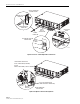
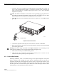
ADCP-75-136 • Issue 1 • November 2002 OPTICAL CONNECTOR ASSEMBLY DETAIL FORWARD PATH (TX) CONNECTOR REVERSE PATH (RX) CONNECTOR PORT 1 OPTICAL TRANSCEIVER CABLE GUIDE DETAIL OPTICAL CONNECTOR DESIGNATION CARD AND CLEAR HOLDER DETAIL PLASTIC COVER CARD HOLDER CABLE GUIDES 17274-A Figure 19. Ports 1–6 Fiber Optic Cable Connections TRANSCEIVER COLOR CODE BLUE = SINGLE-MODE (9 MICRON) BLACK/ BEIGE = MULTI-MODE (50 OR 62.
ADCP-75-136 • Issue 1 • November 2002 7. Remove the dust caps from the optical fiber connectors and the port 1 optical transceiver. Note: Leave the dust cap in place on any unused optical transceiver. 8. Clean each connector (follow connector supplier’s recommendations) and then insert the optical fiber connector pair into DHU optical port 1 (see Figure 19). 9.
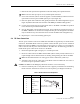
ADCP-75-136 • Issue 1 • November 2002 5. Connect the DC power cable to the DHU port 1 DC PWR jack as shown in Figure 21. 6. Place the DC power cable within the cable guides provided (see Figure 21) and then dress and secure the cable at the DHU per standard industry practice. RJ-45 CONNECTOR DETAIL 1 8 RJ-45 CONNECTOR PORT 1 DC POWER CONNECTOR 17275-A CABLE GUIDE DETAIL CABLE GUIDES Figure 21. 48 Vdc Power Cable Connection 7.
ADCP-75-136 • Issue 1 • November 2002 3. Strip back the outer cable sheath and insulation to expose the wires at both ends of the cable and strip back 0.2 inches (5 mm) of insulation each wire. 4. Connect the Major alarm wire pair to the MAJOR COM/NC or MAJOR COM/NO terminals (whichever is required by the external alarm system) on the DHU alarm terminal connector (supplied with DHU) as shown in Figure 22.
ADCP-75-136 • Issue 1 • November 2002 1. Locate the AC power cord which is provided separately with the DHU. Use only the AC power cord provided with the DHU or an equivalent UL/CUL listed 3-conductor, 18 AWG cord terminated in a molded-on plug cap rated 125 V, 15 A with a maximum length of 6 feet (1.8 m). Note: The DHU is intended to be used with a 3-wire grounding type plug which has a grounding pin. Equipment grounding is required to ensure safe operation. Do not defeat the grounding means.
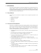
ADCP-75-136 • Issue 1 • November 2002 5 SYSTEM OPERATION This section provides guidelines for turning-up the Digivance ICS, verifying that all units are operating properly, testing to ensure that all performance requirements are satisfied, and correcting any installation problems. This process assumes that the various units that comprise the Digivance ICS have been installed in accordance with the system design plan and the BTS interface device has been installed and tested. 5.
ADCP-75-136 • Issue 1 • November 2002 11. Verify that the HOST PORT LED on the DEU turns green. 12. Place the PORT 1 ON/OFF switch on the DEU in the ON position (press I). 13. Verify that the PORT 1 OK/NOK LED on the DEU turns yellow (for approximately six seconds) and then green. 14. Verify that the STATUS LED on the DRU connected to PORT 1 turns yellow (for approximately six seconds) and then green. 15.
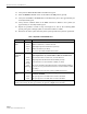
ADCP-75-136 • Issue 1 • November 2002 Table 8. Digital Expansion Unit LED Indicators INDICATOR UNIT LED COLOR Green Yellow Red Off HOST PORT LED Green Red (blinking) Off PORT 1–6 OK/NOK LEDs Green Yellow Red (steady) Red (blinking) Off DESCRIPTION Indicates when the DEU is normal or faulty. DEU in normal state, no faults detected. DEU high temperature fault detected. (see Note) DEU internal fault detected. (see Note) AC power off to DEU or DEU internal fault.
ADCP-75-136 • Issue 1 • November 2002 5.3 Test System Performance Testing the performance of the system involves completing various RF tests and telephone service tests that verify if the system is functioning properly. Use the following procedure to test the system performance: 1. Verify that the forward path (downlink) input signal level at the DHU is optimized. The peak COMPOSITE forward path input signal level at the DHU should be set at –20 dBm.
ADCP-75-136 • Issue 1 • November 2002 6 SYSTEM MAINTENANCE PROCEDURES This section explains the alarm reporting system, provides a method for isolating and troubleshooting faults, and provides procedures for replacing the modular transceivers and the DHU or DEU cooling fans. The Digivance ICS requires no regular maintenance to insure continuous and satisfactory operation. Maintenance, as it applies to the Digivance ICS, primarily involves diagnosing and correcting service problems as they occur.
ADCP-75-136 • Issue 1 • November 2002 6.3 Fault Isolation and Troubleshooting Fault isolation and troubleshooting guidelines are provided in Tables 11, 12, 13, and 14. When an alarm is reported, determine the type of alarm generated (minor or major) and then check the LED indicators on the DHU and note any that are red, yellow, or off.
ADCP-75-136 • Issue 1 • November 2002 Table 11. DHU Fault Isolation and Troubleshooting Guidelines (Continued) Alarm Type LED LED COLOR Major OVERDRIVE Red Problem: Forward path RF input level too high. POSSIBLE CAUSE CORRECTIVE ACTION/COMMENTS 1. Incorrect attenuation in forward path RF coaxial link. 1. Adjust attenuation at interface device. Alarm Type LED LED COLOR Minor OK/NOK Yellow Problem: The DHU is receiving a minor alarm signal from the DEU.
ADCP-75-136 • Issue 1 • November 2002 Table 12. DEU Fault Isolation and Troubleshooting Guidelines Alarm Type LED LED COLOR Minor UNIT Yellow Problem : The DEU is overheating. POSSIBLE CAUSE CORRECTIVE ACTION/COMMENTS 1. Air intake or exhaust openings to DEU chassis blocked. 2. Ambient temperature > 50º C/122º F. 3. Faulty fan. 1. Remove cause of air-flow blockage. 2. Reduce ambient temperature. 3. Replace fan (see Subsection 6.5).
ADCP-75-136 • Issue 1 • November 2002 Table 12. DEU Fault Isolation and Troubleshooting Guidelines (Continued) Alarm Type LED LED COLOR Major OK/NOK Red Problem: The DEU is receiving a major alarm signal from the connected DRU. POSSIBLE CAUSE CORRECTIVE ACTION/COMMENTS 1. Faulty forward path optical fiber between DEU 1. Clean optical connector and then test optical fiber. Repair or replace if faulty (see Subsection 6.4.2). and DRU. 2. Make sure transceiver is fully plugged in and then 2.
ADCP-75-136 • Issue 1 • November 2002 Table 14. System Fault Isolation and Troubleshooting Guidelines Alarm Type LED LED COLOR None All Normal Problem: Loss of phone service from one DRU. Service normal at all other DRU’s. POSSIBLE CAUSE CORRECTIVE ACTION/COMMENTS 1. DRU antenna cable disconnected. 2. DRU antenna obstructed or misdirected. 3. DRU antenna faulty. 4. DRU faulty. 1. Re-connect DRU antenna cable to DRU. 2. Remove antenna obstruction or re-orient antenna. 3. Replace antenna. 4.
ADCP-75-136 • Issue 1 • November 2002 6.4 Test Procedures 6.4.1 Optical Loopback Test Procedure Dirty optical connectors, a faulty optical transceiver, a break in an optical fiber, or a fault in an optical connector will interrupt communications between fiber-linked components. Use the following procedure to determine if a fault exists with an optical port or with an optical fiber: Danger: This equipment uses a Class 1 Laser according to FDA/CDRH rules.
ADCP-75-136 • Issue 1 • November 2002 6. The PORT OK/NOK LED will turn either blinking red or green. If the LED turns blinking red, the optical port is faulty. Replace the optical transceiver and then recheck system operation. If the LED turns green, the optical port is good. Proceed to step 7 to continue the test procedure. 7. Place the PORT ON/OFF switch in the OFF position (press O). 8. Disconnect the loopback from the DHU or supporting DEU. 9.
ADCP-75-136 • Issue 1 • November 2002 OPTICAL LOOPBACK CONNECTION DETAIL 17282-A OPTICAL TRANSCEIVER OPTICAL LOOPBACK Figure 27. DRU Loopback Test 21. The DRU STATUS LED or DEU HOST LED will turn either blinking red or green. If the LED turns blinking red, the optical port is faulty and the optical transceiver must be replaced. If the LED turns green, the optical port is good. 22. At the DHU or supporting DEU, place the PORT ON/OFF switch in the OFF position (press O). 23.
ADCP-75-136 • Issue 1 • November 2002 3. Disconnect the optical connectors at the DHU or supporting DEU and at the corresponding DRU or remote DEU. 4. Inspect the optical connectors. Verify that each connector is clean and that no scratches or imperfections are visible on the fiber end. Clean and polish the optical connector if necessary. 5. Connect a laser light source to one end of the first optical fiber and an optical power meter to the other end. 6.