
User Manual


ADCP-75-136 • Issue 1 • November 2002
Page 36
©
2002,
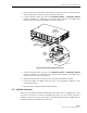
ADC
Telecommunications,
Inc.
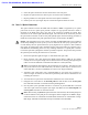
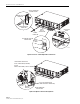
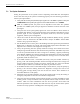
5.
Connect
the
DC
power
cable
to
the
DHU
port
1
DC
PWR
jack
as
shown
in
Figure
21.
6.
Place
the
DC
power
cable
within
the
cable
guides
provided
(see
Figure
21)
and
then
dress
and
secure
the
cable
at
the
DHU
per
standard
industry
practice.
17275-A
RJ-45 CONNECTOR
DETAIL
PORT 1
DC POWER
CONNECTOR
RJ-45
CONNECTOR
CABLE
GUIDES
CABLE GUIDE
DETAIL
1
8
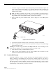
Figure 21. 48 Vdc Power Cable Connection
7.
Connect
the
DC
power
cable
to
the
DRU
as
specified
in
the
instructions
provided
with
that
unit.
8.
Repeat
steps
1–7
for
each
remaining
DRU
that
will
be
powered
by
the
DHU.
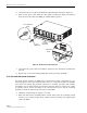
4.10 External Alarm System Connections
The
alarm
interface
between
the
DHU
and
an
external
alarm
system
is
supported
by
a
six-
terminal
plug
(with
screw-type
terminals)
that
connects
to
a
receptacle
mounted
on
the
DHU
front
panel.
The
terminal
plug
provides
connections
to
normally
open
(NO)
and
normally
closed
(NC)
dry
type
alarm
contacts
for
both
minor
and
major
alarms.
A
category
3
or
5
cable
is
typically
used
to
connect
the
DHU
to
the
external
alarm
system.
Use
the
following
procedure
to
install
the
alarm
wiring
and
connect
it
to
the
DHU:
1.
Obtain
the
required
length
of
category
3
or
5
cable.
2.
Route
the
cable
between
the
DHU
and
the
external
alarm
system
(if
not
already
routed)
and
then
cut
to
required
length.
Allow
sufficient
slack
for
dressing
and
organizing
the
cable
at
the
DHU.