
User Manual


ADCP-75-136 • Issue 1 • November 2002
Page 37
©
2002,
ADC
Telecommunications,
Inc.
3.
Strip
back
the
outer
cable
sheath
and
insulation
to
expose
the
wires
at
both
ends
of
the
cable
and
strip
back
0.2
inches
(5
mm)
of
insulation
each
wire.
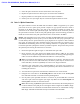
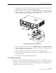
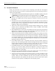
4.
Connect
the
Major
alarm
wire
pair
to
the
MAJOR
COM/NC
or
MAJOR
COM/NO
terminals
(whichever
is
required
by
the
external
alarm
system)
on
the
DHU
alarm
terminal
connector
(supplied
with
DHU)
as
shown
in
Figure
22.
17278-A
ALARM
CONNECTOR
RECEPTACLE
MAJOR
ALARM
WIRES
MINOR
ALARM
WIRES
ALARM CONNECTOR
DETAIL
ALARM
CONNECTOR
NO
COM
NC
MINOR
NO
COM
NC
MAJOR
Figure 22. External Alarm System Connections
5.
Connect
the
Minor
alarm
wire
pair
to
the
MINOR
COM/NC
or
MINOR
COM/NO
terminals
(whichever
is
required
by
the
external
alarm
system)
on
the
DHU
alarm
terminal
connector
as
shown
in
Figure
22.
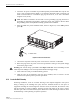
6.
Insert
the
alarm
terminal
connector
into
the
receptacle
on
the
DHU
front
panel.
7.
Connect
the
Major
and
Minor
alarm
wire
pairs
to
the
appropriate
terminals
on
the
external
alarm
system.
8.
Dress
and
secure
cable
per
standard
industry
practice.
4.11 AC Power Connections
The
AC
power
interface
between
the
DHU
and
the
AC
power
source
is
supported
by
a
3-wire
AC
power
cord
connector
located
on
the
DHU
front
panel.
The
AC
connector
provides
a
connection
point
for
the
power
cord
which
is
provided
separately
with
the
DHU.
Use
the
following
procedure
to
install
the
AC
power
cord: