
User Manual


ADCP-75-136 • Issue 1 • November 2002
Page 38
©
2002,
ADC
Telecommunications,
Inc.
1.
Locate
the
AC
power
cord
which
is
provided
separately
with
the
DHU.
Use
only
the
AC
power
cord
provided
with
the
DHU
or
an
equivalent
UL/CUL
listed
3-conductor,
18
AWG
cord
terminated
in
a
molded-on
plug
cap
rated
125
V,
15
A
with
a
maximum
length
of
6
feet
(1.8
m).
Note:
The
DHU
is
intended
to
be
used
with
a
3-wire
grounding
type
plug
which
has
a
grounding
pin.
Equipment
grounding
is
required
to
ensure
safe
operation.
Do
not
defeat
the
grounding
means.
Verify
DHU
is
reliably
grounded
when
installed.
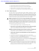
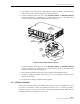
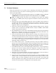
2.
Place
the
DHU
AC
power
ON/OFF
switch,
shown
in
Figure
23,
in
the
OFF
position
(press
O).
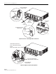
17276-A
AC POWER CORD
Figure 23. AC Power Connection
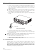
3.
Connect
the
receptacle
end
of
the
power
cord
to
the
AC
connector
on
the
DHU.
4.
Route
the
plug
end
of
the
power
cord
to
the
specified
AC
outlet
(per
the
system
design)
and
connect
plug
to
outlet.
Warning:
The
current
rating
of
the
DHU
is
2.0
Amps
at
120
Vac.
Avoid
overloading
circuits
which
may
cause
damage
to
over-current
protection
devices
and
supply
wiring.
5.
Dress
and
secure
cable
per
standard
industry
practice.
6.
When
all
units
of
the
Digivance
ICS
have
been
installed,
refer
to
Section
4
of
this
manual
for
the
system
power
up
and
test
procedures.
4.12 Create As-Built Drawing
Following
installation,
create
an
“as-built”
drawing
of
the
complete
Digivance
ICS
system.
Using
a
drawing
of
the
building
floor
plan,
show
the
installed
location
of
each
piece
of
equipment
including
the
various
Digivance
electronic
units,
the
antennas,
the
interface
units,
and
the
microcell
(if
used).
In
addition,
show
the
location
and
routing
of
all
copper,
coaxial,
and
fiber
optic
cable
runs
used
with
the
system.
Retain
the
as-built
drawing
for
reference
when
troubleshooting
or
when
planning
for
system
expansion.