
User Manual


ADCP-75-136 • Issue 1 • November 2002
Page 40
©
2002,
ADC
Telecommunications,
Inc.
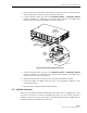
11.
Verify
that
the
HOST
PORT
LED
on
the
DEU
turns
green.
12.
Place
the
PORT
1
ON/OFF
switch
on
the
DEU
in
the
ON
position
(press
I).
13.
Verify
that
the
PORT
1
OK/NOK
LED
on
the
DEU
turns
yellow
(for
approximately
six
seconds)
and
then
green.
14.
Verify
that
the
STATUS
LED
on
the
DRU
connected
to
PORT
1
turns
yellow
(for
approximately
six
seconds)
and
then
green.
15.
Repeat
the
procedure
covered
in
steps
5
through
14
for
each
of
the
remaining
DHU
optical
ports
(ports
2
through
6)
that
is
connected
to
a
DEU
or
a
DRU.
16.
Reconnect
the
alarm
system
and
notify
alarm
system
provider
that
system
is
operational.
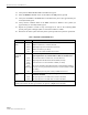
Table 7. Digital Host Unit LED Indicators
INDICATOR COLOR DESCRIPTION
UNIT
LED
Green
Yellow
Red
Off
Indicates
when
the
DHU
is
normal
or
faulty.
DHU
in
normal
state,
no
faults
detected.
DHU
high
temperature
fault
detected.
(see
Note)
DHU
fault
detected
(see
Note).
AC
power
off
to
DHU
or
DHU
internal
fault.
PORT
1–6
OK/NOK
LEDs
Green
Yellow
Red
(steady)
Red
(blinking)
Off
Indicates
if
any
connected
DEU
or
DRU
is
normal
or
faulty
or
if
the
optical
inputs
from
any
connected
DEU
or
DRU
are
normal
or
lost.
All
connected
units
in
normal
state,
no
faults
detected.
High
temperature
fault
detected
in
connected
DEU.
(see
Note)
Fault
detected
in
a
connected
DEU
or
DRU.
(see
Note)
No
reverse
path
optical
signal
detected
from
a
connected
DEU
or
DRU
or
excessive
reverse
path
errors
detected
from
a
connected
DEU
or
DRU.
(see
Note)
Port
disabled
(via
front
panel
switch)
or
DHU
internal
fault.
OVERDRIVE
LED
Green
Red
Indicates
when
the
forward
path
RF
input
is
below
or
above
the
overdrive
threshold.
RF
input
signal
level
at
DHU
below
overdrive
threshold.
RF
input
signal
level
at
DHU
above
overdrive
threshold.
Note:
Detection
of
any
fault
will
generate
an
alarm.
A
high
temperature
fault
will
generate
a
minor
alarm
(yellow
LED).
All
other
types
of
faults
will
generate
a
major
alarm
(red
LED).