
User Manual


ADCP-75-136 • Issue 1 • November 2002
Page 53
©
2002,
ADC
Telecommunications,
Inc.
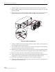
3.
Connect
the
DC
power
cable
to
the
RJ-45
circuit
access
tool
(see
Figure
28).
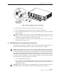
4.
Using
a
DC
voltmeter,
verify
that
the
DC
voltage
level
is
between
34
and
48
Vdc
between
any
set
of
positive
and
negative
(+/-)
terminals
at
the
RJ-45
circuit
access
tool
as
shown
in
Figure
29.
Due
to
source
current
limiting
at
the
DHU
or
DEU,
low
voltage
can
mean
excess
wire
resistance,
low
source
voltage,
or
excess
remote
current.
Warning:
The
DRU
uses
48
Vdc
power.
To
avoid
electric
shock
or
burns,
use
extreme
care
when
working
near
exposed
terminals
or
uninsulated
cables.
Be
careful
not
to
touch
exposed
terminals
or
to
cause
a
short
between
terminals
when
checking
voltage
levels.
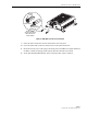
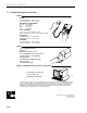
16206-B
POSITIVE (+)
TEST POINTS
1, 3, 5, AND 7
NEGATIVE (-)
TEST POINTS
2, 4, 6, AND 8
Figure 29. RJ-45 Circuit Access Tool Pin/Wire Designations
5.
Disconnect
RJ-45
circuit
access
tool
from
the
DRU.
6.
Use
the
DC
voltmeter
to
check
for
open
pin
connections
by
checking
for
voltage
between
the
+/–
pairs
on
the
RJ-45
circuit
access
tool
(see
Figure
29).
7.
Disconnect
the
DC
power
cable
from
the
RJ-45
circuit
access
tool.
8.
Re-connect
DC
power
cable
to
the
DRU.
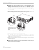
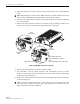
6.5 DHU or DEU Fan Replacement Procedure
It
is
recommended
that
the
fans
(catalog
#
DGVI-100000FAN)
be
replaced
every
five
years.
Replacement
of
a
fan
requires
that
the
DHU
or
DEU
be
turned
off
for
a
short
period
of
time.
This
will
drop
all
existing
calls,
cause
a
temporary
loss
of
service,
and
generate
a
major
alarm.
Use
the
following
procedure
to
replace
the
cooling
fans
within
the
DHU
or
the
DEU:
1.
Before
touching
the
DHU
or
DEU
or
handling
a
fan,
slip
on
an
Electro-Static
Discharge
(ESD)
wrist
strap
and
connect
the
ground
wire
to
an
earth
ground
source.
Wear
the
ESD
wrist
strap
while
completing
each
section
of
the
fan
installation
procedure.
Warning:
Electronic
components
can
be
damaged
by
static
electrical
discharge.
To
prevent
ESD
damage,
always
wear
an
ESD
wrist
strap
when
working
on
the
DHU
or
DEU
and
when
handling
electronic
components.
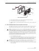
2.
Observe
the
fans
(located
on
right
side
of
enclosure)
to
determine
which
fan
requires
replacement.
The
faulty
fan
may
be
stopped,
running
at
a
reduced
speed,
or
the
fan
bearing
may
be
noisy.
Note:
Because
the
Mean
Time
Between
Failures
(MBTF)
is
the
same
for
both
fans,
it
may
be
more
efficient
to
replace
both
fans
at
the
same
time.
FCC ID: F8I-DISSMRAA, Partial User Manual, 4 of 4