
User Manual


ADCP-75-136 • Issue 1 • November 2002
Page 54
©
2002,
ADC
Telecommunications,
Inc.
3.
Notify
the
NOC
or
alarm
monitoring
system
operator
that
the
system
is
going
offline.
4.
Place
the
DHU
or
DEU
AC
power
On/Off
switch
(see
Figure
3
or
Figure
7)
in
the
OFF
position
(press
O).
5.
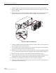
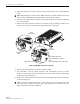
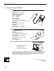
Remove
the
six
flat-head
screws
(requires
TORX
screwdriver
with
T15
bit)
that
secure
the
fan/grill
assembly
to
the
side
of
the
enclosure
as
shown
in
Figure
30
and
save
for
reuse.
16172-B
Figure 30. Fan/Grill Assembly Removal
6.
Carefully
withdraw
the
fan/grill
assembly
from
the
enclosure
until
the
wiring
harness
is
exposed
and
the
connectors
are
accessible.
7.
Lift
the
small
latch
on
each
wiring
harness
connector
(see
Figure
30)
and
carefully
unplug
each
connector
from
the
circuit
board
connector.
8.
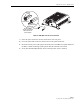
Remove
the
four
plastic
rivets
that
secure
the
faulty
fan
to
the
grill
by
pushing
outward
on
rivet
center
post
until
the
rivet
can
be
withdrawn
from
the
grill
as
shown
in
Figure
31.
9.
Remove
the
faulty
fan(s)
from
the
grill
and
then
locate
the
replacement
fan(s).
10.
Use
the
rivets
removed
in
step
8
to
secure
the
replacement
fan
to
the
grill.
Orient
the
fan
so
the
wiring
harness
is
on
the
top
and
the
arrow
on
the
fan
housing
faces
into
the
enclosure.
11.
Connect
the
two
wiring
harness
connectors
to
the
circuit
board
connectors.
12.
Secure
the
fan/grill
assembly
to
the
side
of
the
enclosure
(see
Figure
30)
using
the
six
flat-head
screws
removed
in
step
5.