
User Manual


ADCP-75-136 • Issue 1 • November 2002
Page 58
©
2002,
ADC
Telecommunications,
Inc.
3.
Disconnect
the
DC
power
cable
connector
from
the
RJ-45
power
jack
on
the
DRU
front
panel.
Note:
Disconnecting
the
power
from
the
DRU
will
create
an
alarm
condition.
Inform
the
NOC
or
alarm
monitoring
system
operator
that
the
alarm
will
be
reported.
4.
Disconnect
the
optical
fiber
connectors
from
the
optical
transceiver
and
place
a
dust
cap
over
each
connector.
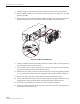
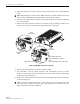
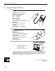
5.
Release
the
optical
transceiver
from
the
transceiver
socket
by
pulling
outward
on
the
release
lever
(if
type
A)
or
release
tab
(if
type
B)
as
shown
in
Figure
34.
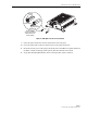
17285-A
TYPE A
TRANSCEIVER
TYPE B
TRANSCEIVER
RELEASE
LEVER
RELEASE TAB
TRANSCEIVER COLOR CODE
BLUE = SINGLE-MODE (9 MICRON)
BLACK/
BEIGE = MULTI-MODE (50 OR 62.5 MICRON)
Figure 34. DRU Optical Transceiver Removal
6.
Remove
the
optical
transceiver
from
the
transceiver
socket.
7.
For
replacement,
select
an
optical
transceiver
that
corresponds
to
the
type
of
fiber
(single-
or
multi-mode)
used
in
the
installation.
The
color
of
the
transceiver
corresponds
to
the
fiber
type
(see
Figure
34).
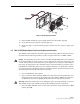
8.
Remove
the
optical
transceiver
from
the
anti-static
packaging
and
orient
for
installation
as
shown
in
Figure
35.
Note:
Two
types
of
optical
transceivers,
type
A
and
type
B,
are
available.
Both
types
provide
the
same
functionality.
On
the
type
A
optical
transceiver,
the
release
lever
(see
Figure
34)
must
be
closed
for
installation.