
User Manual


ADCP-75-150 • Preliminary Issue A • March 2003 • Section 2: Description
Page 2-19
©
2003,
ADC
Telecommunications,
Inc.
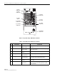
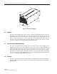
6 LINEAR POWER AMPLIFIER
The
Linear
Power
Amplifier
(LPA),
shown
in
Figure 2-9,
works
is
conjunction
with
the
STM
to
amplify
the
forward
path
RF
output
signal.
The
STM
is
interfaced
with
the
LPA
through
the
D-
sub
connectors
and
wiring
harness
located
at
the
rear
of
the
RU
cabinet/mounting
shelf.
The
RF
signal
is
passed
to
the
LPA
for
amplification
and
then
passed
back
to
the
STM
for
filtering
and
output
via
the
STM’s
ANTENNA
port.
The
STM
also
supplies
DC
power
to
the
LPA
through
the
same
interface.
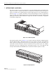
6.1 Primary Components
The
LPA
consists
of
several
electronic
circuit
board
assemblies
and
one
fan
that
are
mounted
within
a
powder-paint
coated
sheet
metal
enclosure.
The
metal
enclosure
provides
a
mounting
point
for
the
electronic
components
and
controls
RF
emissions.
Except
for
the
fan
unit,
the
electronic
components
are
not
user
replaceable.
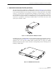
The
LPA
is
designed
for
use
within
the
RU
outdoor
cabinet
or
indoor
mounting
shelf.
Except
for
the
STM
interface
connector,
all
controls,
indicators,
and
switches
are
mounted
on
the
LPA
front
panel
for
easy
access.
A
carrying
handle
is
provided
on
the
front
of
the
LPA
to
facilitate
installation
and
transport.
8 STANDBY Multi-colored
LED
(green/yellow/red)
Indicates
if
the
system
is
in
the
Normal
state
(off)
Standby
state
(blinking
green),
Test
state
(blink-
ing
red),
or
Program
Load
state
(blinking
yel-
low).
See
Note.
9 HOST
UNIT Multi-colored
LED
(green/yellow/red)
Indicates
if
no
alarm
(green),
a
minor
alarm
(yel-
low),
or
a
major
alarm
(red)
is
reported
by
the
HU.
See
Note.
10 STM Multi-colored
LED
(green/yellow/red)
Indicates
if
the
STM
is
normal
(green)
or
faulty
(red).
See
Note.
11 PA Multi-colored
LED
(green/yellow/red)
Indicates
if
the
power
amplifier
is
normal
(green),
over
temperature
(yellow),
has
a
fan
fail-
ure
(yellow),
or
is
faulty
(red).
See
Note.
12 VSWR Multi-colored
LED
(green/yellow/red)
Indicates
if
the
forward
path
VSWR
is
above
(red)
or
below
(green)
the
fault
threshold.
13 PORT
1/PORT
2 Multi-colored
LED
(green/yellow/red)
Indicates
if
the
forward
path
optical
signal
received
from
the
HU
is
normal
(green)
or
if
errors
are
detected
(red).
See
Note.
14 ALARM
IN
MINOR
ALARM
IN
MAJOR
Screw-type
terminal
connector
(14–26
AWG)
Connection
point
for
two
external
alarm
inputs.
The
door-open
switch
lead
wires
are
typically
connected
to
the
major
alarm
terminals.
15 ANTENNA N-type
female
RF
coaxial
connector
Connection
point
for
the
antenna.
Note:
A
more
detailed
description
of
LED
operation
is
provided
in
Section
5.
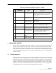
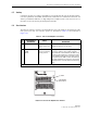
Table 2-4. Spectrum Transport Module User Interface, continued
REF
NO
USER INTERFACE
DESIGNATION
DEVICE
FUNCTIONAL
DESCRIPTION