
User Manual


ADCP-75-150 • Preliminary Issue A • March 2003 • Section 2: Description
Page 2-20
©
2003,
ADC
Telecommunications,
Inc.
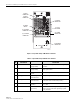
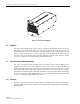
Figure 2-9. Linear Power Amplifier
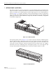
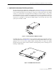
6.2 Mounting
The
LPA
mounts
within
the
RU
outdoor
cabinet
or
indoor
mounting
shelf.
Runners
on
the
top
and
bottom
of
the
LPA
mesh
with
tracks.
The
runners
and
tracks
guide
the
LPA
into
the
installed
position.
The
electrical
interface
between
the
STM
and
LPA
is
supported
by
a
D-sub
female
connector
located
on
the
rear
side
of
the
LPA.
A
corresponding
D-sub
male
connector
mounted
at
the
rear
of
the
RU
cabinet/mounting
shelf
mates
with
the
LPA
connector.
Captive
screws
are
provided
for
securing
the
LPA
in
the
installed
position.
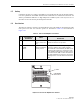
6.3 Fault Detection and Alarm Reporting
The
LPA
in
conjunction
with
the
STM
detects
and
reports
various
faults
including
power
amplifier
fault,
output
power
fault,
temperature
fault,
and
fan
fault.
A
single
Light
Emitting
Diode
(LED)
indicator,
located
on
the
front
panel
of
the
LPA,
turns
from
green
to
red
or
yellow
if
an
LPA
fault
is
detected.
The
status
of
the
LPA,
the
alarm
state
(major
or
minor),
and
other
information
is
summarized
and
reported
(by
the
STM)
over
the
optical
fiber
to
the
HU
and
also
to
the
service
interface.
This
information
may
be
accessed
remotely
through
the
NOC/NEM
interface
or
locally
through
the
DEMS
software
GUI.
6.4 Powering
The
LPA
is
powered
by
various
DC
voltages
which
are
supplied
by
the
STM
over
the
electrical
interface
provided
by
the
D-sub
connectors
and
wiring
harness
mounted
within
the
RU
cabinet/
mounting
shelf.
18640-A
STATUS
MUTE
NORM
RESET